SlideShare uma empresa Scribd logo
1 de 7
Baixar para ler offline
LETTER

doi:10.1038/nature13008

Fuel gain exceeding unity in an inertially confined
fusion implosion
¨
O. A. Hurricane1, D. A. Callahan1, D. T. Casey1, P. M. Celliers1, C. Cerjan1, E. L. Dewald1, T. R. Dittrich1, T. Doppner1, D. E. Hinkel1,
L. F. Berzak Hopkins1, J. L. Kline2, S. Le Pape1, T. Ma1, A. G. MacPhee1, J. L. Milovich1, A. Pak1, H.-S. Park1, P. K. Patel1,
B. A. Remington1, J. D. Salmonson1, P. T. Springer1 & R. Tommasini1

Ignition is needed to make fusion energy a viable alternative energy
source, but has yet to be achieved1. A key step on the way to ignition
is to have the energy generated through fusion reactions in an
inertially confined fusion plasma exceed the amount of energy
deposited into the deuterium–tritium fusion fuel and hotspot during the implosion process, resulting in a fuel gain greater than
unity. Here we report the achievement of fusion fuel gains exceeding unity on the US National Ignition Facility using a ‘high-foot’
implosion method2,3, which is a manipulation of the laser pulse
shape in a way that reduces instability in the implosion. These
experiments show an order-of-magnitude improvement in yield
performance over past deuterium–tritium implosion experiments.
We also see a significant contribution to the yield from a-particle
self-heating and evidence for the ‘bootstrapping’ required to accelerate the deuterium–tritium fusion burn to eventually ‘run away’
and ignite.
At the National Ignition Facility (NIF), 192 lasers deliver up to
1.9 MJ of light into a gold hohlraum, a cylindrically shaped radiation
cavity (Fig. 1), that converts the energy into a nearly Planckian X-ray
bath. A fraction of the X-rays are absorbed by a capsule generating
,100 Mbar of pressure in the ablator (the outer shell of the capsule).
This ablation pressure, delivered as a series of weak shocks, accelerates
the capsule inwards. Against the inside of the ablator is the deuterium–
tritium (D–T) fuel shell, which is initially in a cryogenic ice state. When
the implosion achieves peak velocity, the fuel has a kinetic energy that
is a fraction of the X-ray energy absorbed by the capsule. As the fuel
stagnates (stops moving), abruptly arrested by the high pressures
forming at the centre of the implosion, the D–T forms a hotspot from
the fuel’s inner surface and PdV work (pressure times volume change) is
done on the hotspot. The hotspot initiates the fusion reactions, producing neutrons and a-particles as the hotspot ion temperature climbs
to many kiloelectronvolts. At sufficient hotspot areal density, (rr)hs .
0.3 g cm22, and ion temperature, Tion . 4 keV (where Boltzmann’s
constant has been suppressed), the hotspot will ‘ignite’ as a-particles
redeposit their energy locally. If the fuel areal density, (rr)fuel . 1 g
cm22 the burn will propagate (heat adjacent cold fuel, causing it also
to fuse and burn) and a run-away self-heating process releases energy
many times greater than that absorbed by the capsule.
Mix of the ablator and D–T can degrade the ability of an inertially
confined fusion implosion to compress the D–T fuel and can also cause
undesirable cooling because high-atomic-number (high-Z) materials
in the D–T hotspot will rapidly radiate away energy in the form of bremsstrahlung emission, the power of emission scaling in proportion to Z2.
Among many motivations, the high-foot implosion2,3 was developed in
the wake of the National Ignition Campaign4,5 (NIC) primarily to
address the possibility that ablation-front-driven instability6,7 was
responsible for part of the observed degraded yield performance1 and
the ablator–fuel mix inferred from X-ray emissions in combination with
primary neutron yield8,9.
1

The high-foot implosion is designed to reduce ablation-frontdriven instability growth and thereby inhibit ablator plastic (carbon–
hydrogen and silicon dopants) from mixing into and contaminating
the D–T hotspot. The laser pulse shape is designed to obtain a relatively
high hohlraum radiation temperature (Trad < 90–100 eV) during the
‘foot’ of the pulse (Fig. 1) and launches three shocks. In contrast, the
NIC implosion pulse shape drives a lower radiation temperature (Trad <
60 eV) in the foot (hence ‘low-foot’) for longer and launches four shocks.
The essential stability benefits of the high-foot scheme can be understood from examining an expression for the linear growth rate of the
ablation-driven Rayleigh–Taylor instability10
sffiffiffiffiffiffiffiffiffiffiffiffiffiffi
kg
{b2 ðFr, nÞkva
cAÀRTI ~a2 ðFr, nÞ
ð1Þ
1zkLr
where k is the perturbation wavenumber, g is the ablator acceleration, Lr
is the density gradient scale length of the ablation front, va is the ablation
velocity, and a2 and b2 are parameters of order unity whose exact values
depend on a heat À Á
 conduction scale-length parameter, n, and the Froude
2
number, Fr~va gLr . The key stabilizing effects of the high-foot drive
9=10

enter through the higher ablation velocity, which scales as Trad , increasing the b2kva ablative stabilization term of equation (1), and throughffiffiffiffiffi
p an
increase in Lr, which reduces the instability term proportional to kg .
The increase in Lr is primarily due to a stronger first shock, which
increases the adiabat of the implosion and prevents the ablator from
becoming so highly compressed (risking break-up) during the implosion. The enhanced stability can be further understood by comparing the
respective in-flight aspect ratios (Rin/DR, where Rin is the ablator inner
radius and DR is the ablator thickness) of the high- and low-foot implosions: for the high-foot implosion, the in-flight aspect ratio is roughly
half that of the low-foot implosion—the amplitude of instability growth
pffiffiffiffiffiffiffiffiffiffiffiffiffiffiffi
is directly related to the exponential of Rin =DR 2 (ref. 11). The tradeoff made to obtain the improved stability of the high-foot implosion is
that the D–T fuel adiabat, a 5 P/PF (usually denoted a), where P is
pressure and PF is the Fermi pressure, is higher, making the fuel less
compressible for a given amount of absorbed energy. (An alternate
definition of the adiabat using Pcold, the minimum D–T pressure at
1000 g cm23, is sometimes used12.) Details of the stability benefits, other
theoretical motivations and trade-offs involved in the high-foot implosion, and the initial results from the first set of five D–T implosion
experiments are described elsewhere2,3.
Deuterium–tritium implosions N130927 and N131119 (NIF shot
number in year–month–day format YYMMDD) build on the previous
high-foot shot, N1308123, by modestly increasing the NIF laser power
and energy (Table 1) and by redistributing energy between different
laser beams, through laser wavelength changes that affect the crossbeam transfer (the transfer of power from one beam to another via
induced Brillouin scattering), to optimize the illumination pattern in

Lawrence Livermore National Laboratory, PO Box 808, Livermore, California 94551, USA. 2Los Alamos National Laboratory, Los Alamos, New Mexico 87545, USA.
0 0 M O N T H 2 0 1 4 | VO L 0 0 0 | N AT U R E | 1

©2014 Macmillan Publishers Limited. All rights reserved
RESEARCH LETTER
a

b

Inner cone

Shot
N130927

23.5°
30°

23.5°

44.5°

30°
44.5°

50° 44.5°
50°

Outer cone
D–T ice layer

44.5° 50°

2.263 mm
CH ablator graded
2% Si doped
Cryogenic cooling ring

c
Au hohlraum

300

N130927
3 shock

Trad (eV)

200
Laser
entrance hole

N110914
4 shock

High foot

100

Low foot
0.0
0.0

Laser quads

5.0

10.0

15.0

20.0

t (ns)

Figure 1 | Indirectly driven, inertially confined fusion target for NIF.
a, Schematic NIF ignition target showing a cut-away of the gold hohlraum and
plastic capsule with representative laser bundles incident on the inside surface
of the hohlraum. b, X-ray image of the actual capsule for N130927 with D–T

fuel layer and surrounding CH (carbon–hydrogen) plastic ablator. c, X-ray
radiation drive temperature versus time for the NIC low-foot implosion and the
post-NIC high-foot implosion.

the hohlraum13–16. Although the hotspot shape changes that result
from these wavelength changes can be predicted to some extent17, in
practice the precise wavelengths needed to achieve the desired (that is,
round) shape are found empirically. For N130927, the choice of
˚
l23.5 2 l30 5 0.7 A between the 23.5u and 30.0u inner-cone beams was
˚
chosen for azimuthal symmetry control, with Dl23.5–outer 5 9.2 A and
˚
Dl30–outer 5 8.5 A (the respective laser wavelength differences between
the 23.5u and 30u inner-cone beams and the outer-cone beams) used for
equatorial symmetry control (see Fig. 1 for beam angles). For N131119,
˚
˚
Dl23.5–outer 5 9.5 A and Dl30–outer 5 8.8 A. These wavelength choices
were critical for keeping the hotspot shape under control as the implosion was pushed to higher velocities, because previous experiments had
already shown the tendency for the hotspot to deform into an oblate
toroidal shape when laser power was increased3. There are limits to the
amount of control that can be exerted over the hotspot shape just

through wavelength changes alone, and physical changes to the hohlraum may also be required in future experiments to maintain hotspot
(and fuel) shapes that will achieve the desired results.
We used a gold hohlraum of 5.75-mm diameter and 9.425-mm
length, which are typical values in most high-foot cryogenic D–T
implosion experiments (Fig. 1). The same hohlraum geometry was
used during the NIC for most of the low-foot shots. As is typical for
the high-foot series, the hohlraum was filled with helium gas of 1.6 mg
cm23 density (as compared with 0.96 mg cm23 for the NIC), the purpose of which is to restrict and delay ingress of gold plasma from the
inside wall of the hohlraum, which can impede laser beam propagation. The plastic capsule at the centre of the hohlraum for N130927 and
N131119 respectively had outer-shell radii of 1.1315 and 1.1241 mm
and inner-shell radii of 0.9365 and 0.9303 mm (Fig. 1). Layered on the
inner surface of the capsule shell for N130927 and N131119 were 71.4

Table 1 | Measured and derived implosion performance metrics
Quantity

Y13–15 (neutron)
Tion (keV) D–T
Tion (keV) D–D
DSR (%)
tx (ps)
P0x, P0n (mm)
P2/P0x
P3/P0x
P4/P0x
Ytotal (neutron)
Efusion (kJ)
rhs (mm)
(rr)hs (g cm22)
Ehs (kJ)
Ea (kJ)
EDT,total (kJ)
Gfuel

TW
N131119425MJ
1:9

TW
N130927390MJ
1:8

N13092725

N13092726

N130927 (sim.)

(5.2 6 0.097) 3 1015
5.0 6 0.2
4.3 6 0.2
4.0 6 0.4
152.0 6 33.0
35.8 6 1.0, 34 6 4
20.34 6 0.039
0.015 6 0.027
20.009 6 0.039
6.1 3 1015
17.3
36.6
0.12–0.15
3.9–4.4
2.2–2.6
8.5–9.4
1.8–2.0

(4.4 6 0.11) 3 1015
4.63 6 0.31
3.77 6 0.2
3.85 6 0.41
161.0 6 33.0
35.3 6 1.1, 32 6 4
20.143 6 0.044
20.004 6 0.023
20.05 6 0.023
5.1 3 1015
14.4
35.5
0.12–0.18
3.5–4.2
2.0–2.4
10.2–12.0
1.2–1.4

—
—
—
—
—
—
—
—
—
—
—
34.4–42.3
0.13–0.19
3.7–5.5
2.0–2.4
10.0–13.9
1.04–1.44

—
—
—
—
—
—
—
—
—
—
—
35.7–36.0
0.1–0.14
3.71–4.56
2.0–2.5
10.92–11.19
1.28–1.31

7.6 3 1015
4.2
3.9
4.1
137
32
—
—
—
8.9 3 1015
25.1
32.2
0.15
4.1
2.8
13.4
1.9

Lines 1–9 for columns 2 and 3 are directly measured quantities; others are derived from the data. Columns 4–6 show results from two data-driven models and simulation, respectively.

2 | N AT U R E | VO L 0 0 0 | 0 0 M O N T H 2 0 1 4

©2014 Macmillan Publishers Limited. All rights reserved
LETTER RESEARCH
b

0

20

–50

10

0

–50
–50
0

0
x (μm)

50

100

100

N130927 polar view
Kapton channel

40

y (μm)

50
0

20

–50
–100
–100

10

–50

0
x (μm)

50

100

–50

0
(μm)
x (μm)

50

0
y (μm) 20

20
10
z (μm) 0
15
–10
–20
10

–50

5

–50

0
x (μm)

50

−100

100

−50

0

50

100

0
50
x (μm)

100

N131119 equatorial
x,
100 neutron image um
13–17-MeV neutrons
50 6–12-MeV neutrons

Reconstructed shape for N131119

20

0

–100
–100

–100

–20
25

N131119 polar view
Kapton channel

0
–50

–20
0
x (µm) 20

100

50

30
y (μm)

100

–50

–100
–100
0
–100

N130927 equatorial
100 neutron image
13–17-MeV neutrons
50 6–12-MeV neutrons

30
20
20
10
z (μm) 0
(μ
–10
15
–20
10 –30
–
25

50
5

5
–100
–100

d
Reconstructed shape for N130927

N131119 equatorial view
Kapton channel

y (μm)

30

50
z (μm)

c

100

N130927 equatorial view
Kapton channel

z (μm)
(μm)

100

z (μm)

a

0
–50

–20
0
x (μm) 20

–100
–20 0
y (μm)

20

−100 −50

Figure 2 | X-ray and neutron images of the hotspot at bang-time.
a, Equatorial (side-on) and polar (top-down) views of the hotspot shape for
N130927. Kapton is the filter material in the imaging system that allows
transmission of X-rays with energies of more than 6 keV. b, As in a, but for
N131119. In these X-ray images, the contour shown in white is taken at the
17%-peak-brightness level (the colour scales show the brightness in arbitrary
units) and is used to obtain a description of the shape in Legendre modes

(equatorial view) and Fourier modes (polar view). c, Three-dimensional
reconstructions of the hotspots. d, Superposition of direct (13–17 MeV) and
down-scattered (6–12 MeV) neutron images from N130927 and N131119.
(X-ray image analysis courtesy of N. Izumi, S. Khan, T. Ma and A. Pak of the
NIF Shape Working Group; neutron image analysis courtesy of D. Fittinghoff,
G. Grim, N. Guler and F. Merrill of the NIF Neutron Imaging System Working
Group.)

and, respectively, 69.3 mm of cryogenic D–T ice that was held at 0.8 K
below its triple point for a shot temperature of 18.6 K, like all high-foot
D–T shots. This ‘mini-quench condition’ generally produces an ice
layer with fewer ice cracks than that produced by a full quench18.
Characterization of the capsule surface showed a roughness typical
of implosion capsules for NIF, and characterization of the D–T ice
showed a roughness well within requirements. The very high quality of
the D–T ice layer on N130927 was probably not a significant factor in
its performance because the third-best shot on the NIF (N130812) had
an ice layer that was somewhat worse (with greater surface roughness)
than average. The quality of the D–T layer for N131119 was between
the qualities of the layers for N130812 and N130927.
Table 1 shows the key measurements and performance metrics for
NIF shots N130927 and N131119. Key measured quantities are the
neutron yield, Y13–15, in the 13–15-MeV energy band around the characteristic 14.1-MeV D–T fusion neutron energy; the burn-averaged ion
temperature, Tion; the neutron and X-ray burn widths, respectively tn
and tx; the down-scatter ratio (DSR); and the time of peak neutron
brightness, or ‘bang-time’, tb. On the NIF, Y13–15 is an average of many
diagnostics, including four neutron time-of-flight (NToF) detectors19,
numerous radiochemical activation measurements20 and a magnetic
recoil spectrometer21. The temperature Tion is directly related to the
temporal spread obtained from the full-width at half-maximum of the
NToF detectors. A temporal c-ray history gives tn (for the high-foot
experiments, tx and tn are consistent to within their errors). The DSR
comes from measuring, via NToF and the magnetic recoil spectrometer, the number of neutrons scattered into the energy range 10–
12 MeV, and is directly related to the areal density of the cold D–T fuel,
(rr)fuel  20.3f 3 DSR (where f depends upon the amount of ablator
mass remaining but is typically 0.95 6 0.05 (ref. 21 and B. K. Spears,
personal communication)). Other diagnostics such as X-ray imaging
and neutron imaging (Fig. 2) give information on the shape of the
implosion.
In what follows, we will use the aforementioned observables, which
are measured over the duration of the fusion burn, to infer the amount
of energy that was deposited into the D–T (both fuel and hotspot), to
make a comparison with the amount of energy generated from fusion.
The details of the analysis will focus on N130927; the results for
N131119, which exceeded the performance of N130927, are quoted
in Table 1. The analysis outlined in this letter uses an essentially onedimensional ‘onion-skin’ picture with a hotspot of uniform density

and temperature surrounded by the fuel (with Gaussian or uniform
radial density profile), although the observed three-dimensional hotspot shape information is used to obtain the hotspot volume. Also, an
assumption of approximately equal ion and electron temperatures,
Tion  Te, is made and can be justified post hoc using an expression
for the electron–ion collision time after the hotspot density is obtained.
Analytical and simulation results based on less simplified assumptions
are also quoted in Table 1 for comparison with what is detailed below.
By analysing the observed hotspot shape (Fig. 2) in terms of Legendre
modes (equatorial view, lines 6–9 of Table 1) and Fourier modes (polar
view), where the hotspot perimeter, as defined by the 17%-of-peakbrightness contour, is given by

#
?
X  P‘ 
Rhs ðhÞ~P0 1z
P‘ ðcos hÞ
ð2Þ
P0
‘~2
where P‘ (cos h) is the Legendre function, we obtain the hotspot volume,
Vhs (Methods), and the effective spherical radius, rhs 5 (3Vhs/4p)1/3.
(We note that there is no absolute reference for the X-ray or neutron
images, and so mode ‘ 5 1 is not included in the shape description.
However, ‘ 5 1 and m 5 1 motions can be obtained from the NToF
detectors.) The total neutron yield, Ytotal, can be calculated from
Ytotal 5 Y13–15exp(4DSR), which accounts for the neutrons produced
but then scattered out of the measured 13–15-MeV energy band by
the cold and dense D–T fuel. Because for D–T fusion reactions the
energy per fusion is known (14.1 MeV per neutron and 3.5 MeV per
a-particle), Efusion, the total fusion energy produced, can be calculated
from Ytotal.
From the measured Tion, the D–T reaction rate per unit volume, Æsvæ,
can be calculated using standard formulae22 (Methods). For N130927,
Æsvæ 5 4.75 3 10218–1.03 3 10217 cm3 s21 The range of values is driven by the measurement uncertainty in Tion. The reported Tion values
are actually averages over several detectors. The observed spread in the
individual detector Tion interpretations indicates some motional
broadening contribution, which suggests that the lower temperature
is more representative of the thermal temperature. Throughout this
Letter, the uncertainty ranges given for values for all quoted quantities
are driven by the uncertainty in Tion.
For a 50:50 D–T mix the fusion power density is _DT ~7:04|
10{13 n2 hsvi in joules per cubic centimetre per second, where n is the
yet-unknown number density of the fusing region. From Efusion, Vhs and
0 0 M O N T H 2 0 1 4 | VO L 0 0 0 | N AT U R E | 3

©2014 Macmillan Publishers Limited. All rights reserved
RESEARCH LETTER
tx the hotspot number density can be calculated:
sffiffiffiffiffiffiffiffiffiffiffiffiffiffiffiffiffiffiffiffiffiffiffiffiffiffiffiffiffiffiffiffiffiffiffiffiffiffiffiffiffiffiffiffi
Efusion
n~
7:04|10{13 hsviVhs tx
For N130927, n 5 8.1 3 1024–1.2 3 1025 cm23, a value that also provides the hotspot mass density (assuming a pure D–T hotspot, with

average atomic mass number A~2:5 for D–T), rhs 5 34–50 g cm23;
the hotspot mass, mhs 5 rhsVhs 5 6.4–9.4 mg; and the areal density,
(rr)hs (Table 1).
A number of quantities describing the implosion energetics now
straightforwardly follow. The hotspot pressure can be obtained from

 
Phs ~ðZz1Þrhs Tion =A (Z~1 for D–T), yielding Phs 5 126–152 Gbar.
The hotspot energy is then Ehs ~(3=2)Phs Vhs (Table 1). The fraction,
fa, of a-particle energy deposited into the hotspot can be calculated
from a classic formula23
1
1
 Ãz
fa ~1{ Â
Â
 Ã3
4 ðrr Þhs rla
160 ðrr Þhs rla
where the a-particle stopping range can be found from24
5=4

rla ~

0:025Te

ð3Þ

5=4

1z0:0082Te

in base units of centimetres, grams, and kiloelectronvolts. For N130927,
fa 5 0.68–0.82. The energy deposited in the hotspot by a-particles is
Ea 5 faEfusion/5, recalling that one-fifth of the D–T fusion energy is
emitted in the form of a-particles (the remaining a-particle energy is
deposited into the cold fuel). We note that, using the values found in
Table 1, Ea/Ehs  0.56. These energies fully describe the hotspot, but part
of the implosion energy was used to compress the remaining cold D–T
fuel and so we must examine the fuel to get a full picture of the implosion
energy balance.
Because the D–T hotspot is formed by ablating the inner surface of
the cold D–T fuel as electron conduction transports heat from the
forming hotspot into the fuel, we can calculate the amount of D–T
fuel remaining after the hotspot has formed because we know the

initial amount of D–T ice layered onto the inside of the capsule,
m0 5 186 mg (for N130927): mfuel 5 m0 2 mhs 5 176–179 mg. The cold
D–T fuel mass forms a shell surrounding the hotspot with volume
À3
Á
3
Vfuel ~(4p=3) rout {rhs , where rout is the unknown outer fuel radius.
Ð
Because mfuel ~4p rfuel r2 dr and the measured DSR provides a way
Ð
to obtain the fuel density, rfuel, from ðrr Þfuel ~ rfuel dr, by assuming a
fuel profile we can solve for both the fuel layer thickness, rout 2 rhs, and
density rfuel (Methods). We find that
rffiffiffiffiffiffiffiffiffiffiffiffiffiffiffiffiffiffiffiffiffiffiffiffiffiffiffiffiffi
mfuel
2
rout {rhs ~2s~
{rhs {rhs
ð4Þ
2pðrr Þfuel
with a Gaussian density profile
exp½{(r{r0 )2 =2s2 Š
pffiffiffiffiffi
2ps
where r0 is the radius of peak fuel density. For N130927, rout 2 rhs 5
14.7–15.3 mm, rfuel 5 385–402 g cm23 and Vfuel 5 (3.0–3.2) 3 105 mm3.
The fuel outer radius from these arguments, rout 5 50.8 mm (at 50%
rfuel), is close to that obtained directly from the down-scattered neutron
image (Fig. 2), where P0 5 55.4 mm (at 17% of maximum intensity). By
this time of peak compression, the D–T fuel density has increased by a
factor of more than 1,500. The fuel density is not required for calculating
the fuel energy, but it can be used to estimate the adiabat of the fuel (at
bang-time) assuming that the cold fuel and the hotspot are isobaric
5=3
(Pfuel  Phs), in which case we find that a~Pfuel =PF Phs =0:0021rfuel 5
2.9–3.3 for N130927—the fuel adiabat in flight is lower than this range of
values. The fuel density is also needed to calculate the X-ray losses through
the fuel.
As the hotspot is compressed to high temperatures, the primary
energy loss mechanism is bremsstrahlung X-ray emission because
the D–T hotspot is optically thin to these X-rays. The bremsstrahlung
energy loss is calculated to be24
pffiffiffiffiffi
Ebrems (kJ)~5:34|10{34 n2 Te Vhs tx
hs
r(r)~(rr)fuel

in base units of centimetres, kiloelectronvolts and seconds. For N130927,
Ebrems 5 2.3–4.5 kJ, the low end of which is nearly equivalent to the

15

Self-heating yield/
compression yield

20
1.5
1.0
0.5

N130501

Yield from fuel compression

N131119
N130927
N130812

Yield from self-heating
Energy delivered to D–T fuel

N130710
0.1 0.2 0.3 0.4 0.5 0.6 0.7 0.8
GLC

10
−

Yield (kJ)

0
0

High foot

Low foot
High foot

5

0

110608
110615
110620
110826
110904
110908
110914
111103
111112
111215
120126
120131
120205
120213
120219
120311
120316
120321
120405
120412
120417
120422
120626
120716
120720
120802
120808
120920
130331
130501
130530
130710
130802
130812
130927
131119

Low foot

Shot number

Figure 3 | Yield and energetics metrics for shots on the NIF. Total fusion
yield is plotted versus shot number (that is, time). Shots 110608–130331 are
low-foot shots. Shots 130501–131119 are high-foot shots. The bars showing
total yield are broken into components of yield coming from a-particle selfheating and yield coming from compression. The black dashes denote the
energy delivered to the D–T (fuel plus hotspot) with error bars (black vertical

lines, 1s) as calculated from the model of ref. 25. The plot shows that, even with
the uncertainty in our results, shots 130927 and 131119 both yielded more
fusion energy than was delivered to the D–T. Inset, ratio of self-heating yield to
compression yield versus generalized Lawson criterion (GLC). All error bars,
1s.

4 | N AT U R E | VO L 0 0 0 | 0 0 M O N T H 2 0 1 4

©2014 Macmillan Publishers Limited. All rights reserved
LETTER RESEARCH
a-particle energy deposited. To examine whether or not these X-rays can
escape the dense cold fuel, we can calculate the optical depth of the cold
D–T fuel from tfuel 5 rfuelkDT(rout 2 rhs) using a simple D–T opacity
model, kDT (g cm22) 5 0.352rfuel(hn)23.3[1 2 exp(2hn/Te)]. We find
that for X-ray energies of hn  Tion  Te, the D–T fuel layer is almost
one optical depth, tfuel 5 0.32–0.66, implying that some bremsstrahlung
X-rays deposit energy into the cold fuel whereas some escape. Electron
conduction does not have a significant role in the total D–T energy loss
from the cold fuel at stagnation, but is important for the hotspot energy
loss.
The cold fuel energy at stagnation now follows from the isobaric
assumption, Efuel ~(3=2)Pfuel Vfuel 5 6.9–7.8 kJ (where we have overestimated the fuel internal energy because typically the outer edge of
the fuel has not fully stagnated even at bang-time). The total energy
delivered to the D–T by the implosion is then (Table 1)
1
1
EDT,total ~Ehs zEfuel z e{tfuel Ebrems { Ea
ð5Þ
2
2
The factors of one-half in the radiation term and the a-particle energy
deposition account for having only half the energy emitted or deposited at peak burn. This total D–T energy was calculated with quantities
measured around bang-time, but it represents the kinetic plus internal
energy in the fuel at peak velocity in the implosion. A crosscheck of
EDT,total is provided from calculating the fuel kinetic energy, K, using a
direct measurement of implosion velocity from an earlier high-foot
‘1DConA’ shot, N130409 (at 350 TW and 1.3 MJ of laser power and
energy), where the peak ablator centre-of-mass velocity was measured
to be 267 6 15 km s21, which is equivalent to a fuel velocity of
297 6 15 km s21 (the fuel being at smaller radius and convergence
makes the velocity larger). Scaling the N130409-derived velocity to
0:41
the laser power of N130927 (implosion velocity, vimp !Plaser ) gives a
21
2
fuel velocity of vfuel 5 311 6 15 km s , and so K~(1=2)m0 vfuel ~9:0+
0:9 kJ. The difference between K and EDT,total is the internal energy of the
fuel at peak velocity plus the additional PdV work done by the ablator on
the fuel during the deceleration.
The total fuel energy gain, Gfuel 5 Efusion/EDT,total is now known and
is 1.2–1.4 for N130927. For comparison, in Table 1 we also show
results from other data-derived models of implosion energetics25,26 that
are constructed in the spirit of the above analysis but which differ in
some details. A conduction-limited temperature profile in the hotspot
is added to the above development in one case25 and the other ‘detailed
model’ case includes a three-dimensional, self-consistent physics
model matched to the data26. To complement these analytic datadriven models, in Table 1 we also show the results from a full, onedimensional, radiation–hydrodynamics simulation27 of N130927, with
a multifrequency X-ray drive that is calibrated to shock-timing and
implosion trajectory data, without any mix model applied. The inferences from data and the computer simulation all indicate that
Gfuel . 1. Moreover, we have demonstrated repeatability and improvement with the follow-on shot N131119. It should be understood, however, that Gfuel . 1 indicates only that the output fusion energy exceeds
the energy deposited into the fuel. This is not the same as exceeding
either the energy absorbed by the capsule (defined as the ablator shell
plus D–T fuel), which absorbed ,150 kJ for N130927 and N131119, or
the energy delivered by the laser to the target (defined as the hohlraum
plus capsule), which was 1.8 MJ for N130927 and 1.9 MJ for N131119.
Key yield and energy performance metrics are graphically illustrated
in Fig. 3 for N131119, N130927 and all other D–T implosions carried
out on the NIF since the summer of 2011. Using a key metric for
ignition, the generalized Lawson criterion28 x 5 (Pt)/(Pt)ign (which
is unity at ignition) we see (Fig. 3, inset) that for N131119 we are at
the threshold of achieving yield doubling due to a-particle energy
deposition.
Because most of the quantities associated with inertially confined
fusion that we seek to improve to achieve ignition scale as some positive
power of stagnation pressure, near-term efforts focus on increasing the

implosion speed and controlling the hotspot shape with the present
fuel adiabat. As the implosion speed is increased, we will necessarily
risk giving back some of the gains the high-foot implosion has made in
terms of instability control. New strategies for the hohlraum will also be
explored because at present hohlraum physics is limiting our ability to
use the full power capability on the NIF while maintaining an acceptable hotspot shape (higher laser powers are the most direct way to
increase implosion speed). Future efforts may involve more elaborate
schemes to maintain control over ablator instability while recovering a
lower adiabat for the fuel (for example ‘adiabat shaping’29) or also using
an alternate ablator material.

METHODS SUMMARY
Formulae for the hotspot volume and the D–T reaction rate, and a discussion of
fuel density profiles, are given in Methods. Neutron image shape coefficients are
also given there.
Online Content Any additional Methods, Extended Data display items and Source
Data are available in the online version of the paper; references unique to these
sections appear only in the online paper.
Received 1 November 2013; accepted 7 January 2014.
Published online 12 February 2014.
1.
2.
3.

4.

5.
6.
7.
8.
9.
10.

11.

12.

13.
14.
15.
16.
17.
18.
19.
20.
21.

22.
23.
24.
25.

Edwards, M. J. et al. Progress towards ignition on the National Ignition Facility. Phys.
Plasmas 20, 070501 (2013).
Dittrich, T. R. et al. Design of a high-foot/high-adiabat ICF capsule for the National
Ignition Facility. Phys. Rev. Lett. 112, LJ14108 (2014).
Park, H.-S. et al. High-adiabat, high-foot, inertial confinement fusion implosion
experiments on the National Ignition Facility. Phys. Rev. Lett. 112, LK13998
(2014).
Lindl, J. D.  Moses, E. I. Plans for the National Ignition Campaign (NIC) on the
National Ignition Facility (NIF): on the threshold of initiating ignition experiments.
Phys. Plasmas 18, 050901 (2011).
Glenzer, S. H. et al. Cryogenic thermonuclear fuel implosions on the National
Ignition Facility. Phys. Plasmas 19, 056318 (2012).
Bodner, S. E. Rayleigh-Taylor instability and laser-pellet fusion. Phys. Rev. Lett. 33,
761–764 (1974).
Gonchorov, V. N.  Hurricane, O. A. Panel 3 Report: Implosion Hydrodynamics.
Report LLNL-TR-562104 (Lawrence Livermore National Laboratory, 2012).
Ma, T. et al. Onset of hydrodynamic mix in high-velocity, highly compressed inertial
confinement fusion implosions. Phys. Rev. Lett. 111, 085004 (2013).
Regan, S. P. et al. Hot-spot mix in ignition-scale inertial confinement fusion targets.
Phys. Rev. Lett. 111, 045001 (2013).
Betti, R., Goncharov, V. N., McCrory, R. L.  Verdon, C. P. Growth rates of the
Rayleigh-Taylor instability in inertial confinement fusion. Phys. Plasmas 5,
1446–1454 (1998).
Lindl, J. Development of the indirect-drive approach to inertial confinement fusion
and the target physics basis for ignition and gain. Phys. Plasmas 2, 3933–4024
(1995).
Haan, S. et al. Point design targets, specifications, and requirements for the 2010
ignition campaign on the National Ignition Facility. Phys. Plasmas 18, 051001
(2011).
Michel, P. et al. Tuning the implosion symmetry of ICF targets via controlled
crossed-beam energy transfer. Phys. Rev. Lett. 102, 025004 (2009).
Michel, P. et al. Symmetry tuning via controlled crossed-beam energy transfer on
the National Ignition Facility. Phys. Plasmas 17, 056305 (2010).
Moody, J. D. et al. Multistep redirection by cross-beam power transfer of ultrahighpower lasers in a plasma. Nature Phys. 8, 344–349 (2012).
Callahan, D. A. et al. The velocity campaign for ignition on NIF. Phys. Plasmas 19,
056305 (2012).
Marinak, M. M. et al. Three-dimensional HYDRA simulations of National Ignition
Facility targets. Phys. Plasmas 8, 2275 (2001).
Kozioziemski, B. J. et al. Deuterium-tritium layer formation for the National Ignition
Facility. Fusion Sci. Technol. 59, 14–25 (2011).
Glebov, V. Yu. et al. Development of nuclear diagnostics for the National Ignition
Facility. Rev. Sci. Instrum. 77, 10E715 (2006).
Bleuel, D. L. et al. Neutron activation diagnostics at the National Ignition Facility.
Rev. Sci. Instrum. 83, 10D313 (2012).
Gatu Johnson, M. et al. Neutron spectrometry – an essential tool for
diagnosing implosions at the National Ignition Facility. Rev. Sci. Instrum. 83,
10D308 (2012).
Bosch, H.-S.  Hale, G. M. Improved formulas for fusion cross-section and thermal
reactivities. Nucl. Fusion 32, 611–631 (1992).
Krokhin, O. N.  Rozanov, V. B. Escape of a-particles from a laser-pulse-initiated
thermonuclear reaction. Sov. J. Quantum Electron. 2, 393–394 (1973).
Atzeni, S.  Meyer-ter-Vehn, J. The Physics of Inertial Fusion 32, 398 (Oxford Univ.
Press, 2004).
Patel, P. et al. Performance of DT layered implosions on the NIF. Bull. Am. Phys. Soc.
58, abstr. NO4.00001 (2013).
0 0 M O N T H 2 0 1 4 | VO L 0 0 0 | N AT U R E | 5

©2014 Macmillan Publishers Limited. All rights reserved
RESEARCH LETTER
26. Cerjan, C., Springer, P. T.  Sepke, S. M. Integrated diagnostic analysis of inertial
confinement fusion capsule performance. Phys. Plasmas 20, 056319 (2013).
27. Zimmerman, G. B.  Kruer, W. L. Numerical Simulation of laser initiated fusion.
Comments Plasma Phys. Control. Fusion 2, 85–89 (1975).
28. Betti, R. et al. Thermonuclear ignition in inertial confinement fusion and
comparison with magnetic confinement. Phys. Plasmas 17, 058102 (2010).
29. Goncharov, V. N. et al. Improved performance of direct-drive ICF target designs
with adiabat shaping using an intense picket. Phys. Plasmas 10, 1906–1918
(2003).
Acknowledgements We thank P. Albright, J. Atherton, L. R. Benedetti, D. Bradley,
J. A. Caggiano, R. Dylla-Spears, M. J. Edwards, W. H. Goldstein, B. Goodwin, S. Haan,
A. Hamza, W. Hsing, P. Kervin, J. Kilkenny, B. Kozioziemski, O. Landen, J. Lindl,
B. MacGowan, A. Mackinnon, N. Meezan, J. F. Meeker, J. Moody, E. Moses, D. Pilkington,
T. Parham, J. Ralph, S. Ross, H. Robey, R. Rygg, B. Spears, R. Town, C. Verdon, A. Wan and
B. Van Wonterghem, and the NIF operations, cryogenics and targets teams. We also
thank V. Goncharov and J. Knauer for their advice, and R. Betti for bringing our attention
to equation (3). Thanks also go to NIF’s external collaborators at GA (targets), LLE
(diagnostics), the MIT Plasma Science and Fusion Center (magnetic recoil
spectrometer diagnostic), CEA and AWE. This work was performed under the auspices
of the US Department of Energy by Lawrence Livermore National Laboratory under
contract no. DE-AC52-07NA27344.
Author Contributions O.A.H. was lead scientist for the high-foot campaign, and
performed two-dimensional stability modelling, and one-dimensional pre- and
post-shot analysis. D.A.C. was lead scientist on hotspot shape and hohlraum strategies.

D.T.C. was part of the D–T shot experiment team. P.M.C. performed VISAR data unfolds.
C.C. performed three-dimensional ‘detailed model’ calculations. E.L.D. was lead
experimenter for 1DConA (R(t) trajectory) tuning experiments and capsule re-emission
(early-time symmetry) tuning experiments. T.R.D. performed initial one-dimensional
capsule design, scoping, and one-dimensional pre- and post-shot simulations. T.D. was
lead experimentalist on a 2DConA ablator shape experiment and was part of the D–T
shot team. D.E.H. was the pulse shape design physicist and performed all
two-dimensional integrated hohlraum-capsule simulations. L.F.B.H. was design
physicist for keyhole (shock-timing) tuning experiments. J.L.K. was lead
experimentalist for symcap (hotspot shape) tuning experiments. S.L. was lead
experimentalist for the keyhole (shock-timing) tuning experiments. T.M. was lead
experimentalist for several 2DConA ablator shape experiments, was part of the D–T
shot team, and was lead experimentalist on shot N131119. A.G.M. was part of the
1DConA and D–T experimental teams. J.L.M. was design physicist for the re-emission
experiment. A.P. was part of the D–T shot team. P.K.P. provided a hotspot model
analysis and metrics plots. H.-S.P. was lead experimentalist on D–T implosion shots up
to and including N130927. B.A.R. was overall lead on experiments. J.D.S. constructed
model multifrequency sources normalized to tuning experiments, and performed oneand two-dimensional model scoping. P.T.S. provided a hotspot model analysis. R.T.
provided 1DConA analysis and was shot experimentalist.
Author Information Reprints and permissions information is available at
www.nature.com/reprints. The authors declare no competing financial interests.
Readers are welcome to comment on the online version of the paper. Correspondence
and requests for materials should be addressed to O.A.H. (hurricane1@llnl.gov).

6 | N AT U R E | VO L 0 0 0 | 0 0 M O N T H 2 0 1 4

©2014 Macmillan Publishers Limited. All rights reserved
LETTER RESEARCH
METHODS
Hotspot volume formulae. Using equation (2) the volume is
ð p ð Rhs ðhÞ
Vhs ~2p
0

C0
1=3

Tion
f~1{

R2 dR sin h dh

0

4
4
8
4
~ pP03 z pP0P22 z
pP23 z pP0P32
3
5
105
7
16
4
8
2
2
z
pP2P3 z pP0P4 z pP22 P4
105
9
35
80
8
24
2
2
z
pP2P4 z pP3 P4z
pP43 z Á Á Á
693
77
1,001
A simple correction to this volume can be applied (by multiplying the above
expression by the expression below) to include m-modes (azimuthal modes):
1z

j~


3 M2 2 3 M3 2 3 M4 2
z
z
2 M0
2 M0
2 M0
z

3 M22 M4
cos½4ðw2 {w4 ÞŠ Á Á Á
4 M03

where w2 and w4 are phase offsets of m-modes 2 and 4, respectively.
Deuterium–tritium reaction rate formulae. From ref. 22


hsvi~C1 f{5=6 j2 exp {3f1=3 j
in cubic centimetres per second, where

2
3
C2 Tion zC4 Tion zC6 Tion
2 zC T 3
1zC3 Tion zC5 Tion
7 ion

and C0 5 6.6610, C1 5 6.43413 10214, C2 5 1.51363 1022, C3 5 7.51893 1022,
C4 5 4.60643 1023, C5 5 1.353 1022, C6 5 21.06753 1024 and C7 5 1.3663 1025
when Tion is expressed in kiloelectronvolts.
Deuterium–tritium fuel density profile. Assuming a different density profile
changes the form of equation (4), but changes the numerical value for the fuel
thickness little. For example, assuming a top-hat distribution for the fuel yields
qffiffiffiffiffiffiffiffiffiffiffiffiffiffiffiffiffiffiffiffiffiffiffiffiffiffiffiffiffiffiffiffiffiffiffiffiffiffiffiffiffiffiffi

1
2
3mfuel pðrr Þfuel {3rhs {3rhs =2
rout {rhs ~
2
from which we obtain rout 2 rin 5 15.5–16.2 mm for N130927. The fuel density
does show more sensitivity, being rfuel 5 (rr)fuel/(rout 2 rin) 5 457–478 g cm23 for
pffiffiffiffiffi
a top-hat distribution and rfuel ~ðrr Þfuel 2ps 5 385–402 for a Gaussian. The
Gaussian profile assumption is more consistent with simulated fuel density profiles. The lower fuel density associated with the Gaussian profile increases the
inferred fuel adiabat and decreases the fuel optical depth as compared with the
uniform profile. The lower fuel optical depth makes the X-ray energy contribution
to equation (5) larger; that is, it gives us a more conservative contribution to the
total D–T energy.
Neutron image shape analysis. For N130927, the Legendre mode shape coefficients for the down-scattered neutron image are P0 5 55 6 4 mm, P2/
P0 5 1% 6 5% and P4/P0 5 22%, and for the direct image P0 5 32 6 4 mm, P2/
P0 5 235% 6 5% and P4/P0 5 2%. For the N131119 down-scattered neutron
image, P0 5 50 6 4 mm, P2/P0 5 0% 6 5% and P4/P0 5 2%, and for the direct
image P0 5 34 6 4 mm, P2/P0 5 234% 6 5% and P4/P0 5 1%.

©2014 Macmillan Publishers Limited. All rights reserved

Mais conteúdo relacionado

Mais procurados

IB Chemistry on Nuclear Magnetic Resonance, Chemical Shift and Splitting Pattern
IB Chemistry on Nuclear Magnetic Resonance, Chemical Shift and Splitting PatternIB Chemistry on Nuclear Magnetic Resonance, Chemical Shift and Splitting Pattern
IB Chemistry on Nuclear Magnetic Resonance, Chemical Shift and Splitting PatternLawrence kok
 
6 c-radiation-stefan boltzman
6 c-radiation-stefan boltzman6 c-radiation-stefan boltzman
6 c-radiation-stefan boltzmanRiccardo Rigon
 
Fundamentals of thermal radiations
Fundamentals of thermal radiationsFundamentals of thermal radiations
Fundamentals of thermal radiationsIhsan Wassan
 
Thermal Dynamics and Heat Transfer
Thermal Dynamics and Heat TransferThermal Dynamics and Heat Transfer
Thermal Dynamics and Heat TransferTony Loup
 
Introduction of remote sensing
Introduction of remote sensingIntroduction of remote sensing
Introduction of remote sensingAbran Idrees
 
013 fundamental of thermal radiation
013 fundamental of thermal radiation013 fundamental of thermal radiation
013 fundamental of thermal radiationSaranyu Pilai
 
Astonishing Astronomy 101 - Chapter 3
Astonishing Astronomy 101 - Chapter 3Astonishing Astronomy 101 - Chapter 3
Astonishing Astronomy 101 - Chapter 3Don R. Mueller, Ph.D.
 
Cavity theory-Radiation physics
Cavity theory-Radiation physicsCavity theory-Radiation physics
Cavity theory-Radiation physicsKathiravan E M
 
Pres Css Ifs 3maggio2011
Pres Css Ifs 3maggio2011Pres Css Ifs 3maggio2011
Pres Css Ifs 3maggio2011vincidale
 
Photoacoustic Spectroscopy
Photoacoustic SpectroscopyPhotoacoustic Spectroscopy
Photoacoustic SpectroscopyDeepak Rajput
 
Laser Beam Machining (Modern Manufacturing Process)
Laser Beam Machining (Modern Manufacturing Process)Laser Beam Machining (Modern Manufacturing Process)
Laser Beam Machining (Modern Manufacturing Process)Dinesh Panchal
 
IB Chemistry on Nuclear Magnetic Resonance, Chemical Shift and Splitting Pattern
IB Chemistry on Nuclear Magnetic Resonance, Chemical Shift and Splitting PatternIB Chemistry on Nuclear Magnetic Resonance, Chemical Shift and Splitting Pattern
IB Chemistry on Nuclear Magnetic Resonance, Chemical Shift and Splitting PatternLawrence kok
 
Sound Waves: Relating Amplitude, Power and Intensity
Sound Waves: Relating Amplitude, Power and IntensitySound Waves: Relating Amplitude, Power and Intensity
Sound Waves: Relating Amplitude, Power and Intensitylyssawyh
 
Thermal radiation
Thermal radiationThermal radiation
Thermal radiationcolin yang
 

Mais procurados (20)

Radiation
RadiationRadiation
Radiation
 
IB Chemistry on Nuclear Magnetic Resonance, Chemical Shift and Splitting Pattern
IB Chemistry on Nuclear Magnetic Resonance, Chemical Shift and Splitting PatternIB Chemistry on Nuclear Magnetic Resonance, Chemical Shift and Splitting Pattern
IB Chemistry on Nuclear Magnetic Resonance, Chemical Shift and Splitting Pattern
 
E2 stellar radiation
E2 stellar radiationE2 stellar radiation
E2 stellar radiation
 
6 c-radiation-stefan boltzman
6 c-radiation-stefan boltzman6 c-radiation-stefan boltzman
6 c-radiation-stefan boltzman
 
Fundamentals of thermal radiations
Fundamentals of thermal radiationsFundamentals of thermal radiations
Fundamentals of thermal radiations
 
Thermal Dynamics and Heat Transfer
Thermal Dynamics and Heat TransferThermal Dynamics and Heat Transfer
Thermal Dynamics and Heat Transfer
 
10..fluorescence doc
10..fluorescence doc10..fluorescence doc
10..fluorescence doc
 
Introduction of remote sensing
Introduction of remote sensingIntroduction of remote sensing
Introduction of remote sensing
 
7..fluorescence doc
7..fluorescence doc7..fluorescence doc
7..fluorescence doc
 
013 fundamental of thermal radiation
013 fundamental of thermal radiation013 fundamental of thermal radiation
013 fundamental of thermal radiation
 
NMR
NMRNMR
NMR
 
Astonishing Astronomy 101 - Chapter 3
Astonishing Astronomy 101 - Chapter 3Astonishing Astronomy 101 - Chapter 3
Astonishing Astronomy 101 - Chapter 3
 
Cavity theory-Radiation physics
Cavity theory-Radiation physicsCavity theory-Radiation physics
Cavity theory-Radiation physics
 
Chapter 1b
Chapter 1bChapter 1b
Chapter 1b
 
Pres Css Ifs 3maggio2011
Pres Css Ifs 3maggio2011Pres Css Ifs 3maggio2011
Pres Css Ifs 3maggio2011
 
Photoacoustic Spectroscopy
Photoacoustic SpectroscopyPhotoacoustic Spectroscopy
Photoacoustic Spectroscopy
 
Laser Beam Machining (Modern Manufacturing Process)
Laser Beam Machining (Modern Manufacturing Process)Laser Beam Machining (Modern Manufacturing Process)
Laser Beam Machining (Modern Manufacturing Process)
 
IB Chemistry on Nuclear Magnetic Resonance, Chemical Shift and Splitting Pattern
IB Chemistry on Nuclear Magnetic Resonance, Chemical Shift and Splitting PatternIB Chemistry on Nuclear Magnetic Resonance, Chemical Shift and Splitting Pattern
IB Chemistry on Nuclear Magnetic Resonance, Chemical Shift and Splitting Pattern
 
Sound Waves: Relating Amplitude, Power and Intensity
Sound Waves: Relating Amplitude, Power and IntensitySound Waves: Relating Amplitude, Power and Intensity
Sound Waves: Relating Amplitude, Power and Intensity
 
Thermal radiation
Thermal radiationThermal radiation
Thermal radiation
 

Destaque

Memoria materiales 2015
Memoria materiales 2015Memoria materiales 2015
Memoria materiales 2015Cemre Ozmenci
 
04(t) thermal and chemical effects of electric current
04(t)   thermal and chemical effects of electric current04(t)   thermal and chemical effects of electric current
04(t) thermal and chemical effects of electric currentTafzz Sailo
 
[Phys 6006][Ben Williams][Inertial Confinement Fusion]
[Phys 6006][Ben Williams][Inertial Confinement Fusion][Phys 6006][Ben Williams][Inertial Confinement Fusion]
[Phys 6006][Ben Williams][Inertial Confinement Fusion]Ben Williams
 
Kittel c. introduction to solid state physics 8 th edition - solution manual
Kittel c.  introduction to solid state physics 8 th edition - solution manualKittel c.  introduction to solid state physics 8 th edition - solution manual
Kittel c. introduction to solid state physics 8 th edition - solution manualamnahnura
 
Ch04 with problems
Ch04 with problemsCh04 with problems
Ch04 with problemsklivsie
 
mechanics of materials
mechanics of materialsmechanics of materials
mechanics of materialsAzlan
 
Materials properties
Materials propertiesMaterials properties
Materials propertiesIsabelop
 
Materiales the science and engineering of materials - Solution Manual
Materiales   the science and engineering of materials - Solution ManualMateriales   the science and engineering of materials - Solution Manual
Materiales the science and engineering of materials - Solution ManualMeylis Hydyrow
 
Solid state physics - Crystalline Solids
Solid state physics - Crystalline SolidsSolid state physics - Crystalline Solids
Solid state physics - Crystalline SolidsAthren Tidalgo
 
Introduction to properties of materials
Introduction to properties of materialsIntroduction to properties of materials
Introduction to properties of materialsGulfam Hussain
 
Mechanics of materials solution manual (3 rd ed , by beer, johnston, & dewolf)
Mechanics of materials solution manual (3 rd ed , by beer, johnston, & dewolf)Mechanics of materials solution manual (3 rd ed , by beer, johnston, & dewolf)
Mechanics of materials solution manual (3 rd ed , by beer, johnston, & dewolf)Pawnpac
 
Solution Manuals of Physics Textbooks
Solution Manuals of Physics TextbooksSolution Manuals of Physics Textbooks
Solution Manuals of Physics TextbooksCrazy for Study
 
Optical properties of nanomaterials
Optical properties of nanomaterialsOptical properties of nanomaterials
Optical properties of nanomaterialsudhay roopavath
 

Destaque (20)

Memoria materiales 2015
Memoria materiales 2015Memoria materiales 2015
Memoria materiales 2015
 
04(t) thermal and chemical effects of electric current
04(t)   thermal and chemical effects of electric current04(t)   thermal and chemical effects of electric current
04(t) thermal and chemical effects of electric current
 
[Phys 6006][Ben Williams][Inertial Confinement Fusion]
[Phys 6006][Ben Williams][Inertial Confinement Fusion][Phys 6006][Ben Williams][Inertial Confinement Fusion]
[Phys 6006][Ben Williams][Inertial Confinement Fusion]
 
Kittel c. introduction to solid state physics 8 th edition - solution manual
Kittel c.  introduction to solid state physics 8 th edition - solution manualKittel c.  introduction to solid state physics 8 th edition - solution manual
Kittel c. introduction to solid state physics 8 th edition - solution manual
 
Physics
PhysicsPhysics
Physics
 
Optical properties
Optical propertiesOptical properties
Optical properties
 
Ch04 with problems
Ch04 with problemsCh04 with problems
Ch04 with problems
 
physics lecture
physics lecturephysics lecture
physics lecture
 
Ch04
Ch04Ch04
Ch04
 
mechanics of materials
mechanics of materialsmechanics of materials
mechanics of materials
 
Materials properties
Materials propertiesMaterials properties
Materials properties
 
Materiales the science and engineering of materials - Solution Manual
Materiales   the science and engineering of materials - Solution ManualMateriales   the science and engineering of materials - Solution Manual
Materiales the science and engineering of materials - Solution Manual
 
Solid state physics - Crystalline Solids
Solid state physics - Crystalline SolidsSolid state physics - Crystalline Solids
Solid state physics - Crystalline Solids
 
Introduction to properties of materials
Introduction to properties of materialsIntroduction to properties of materials
Introduction to properties of materials
 
Yc presentation
Yc presentationYc presentation
Yc presentation
 
Ch19
Ch19Ch19
Ch19
 
MECHANICS OF MATERIALS
MECHANICS OF MATERIALSMECHANICS OF MATERIALS
MECHANICS OF MATERIALS
 
Mechanics of materials solution manual (3 rd ed , by beer, johnston, & dewolf)
Mechanics of materials solution manual (3 rd ed , by beer, johnston, & dewolf)Mechanics of materials solution manual (3 rd ed , by beer, johnston, & dewolf)
Mechanics of materials solution manual (3 rd ed , by beer, johnston, & dewolf)
 
Solution Manuals of Physics Textbooks
Solution Manuals of Physics TextbooksSolution Manuals of Physics Textbooks
Solution Manuals of Physics Textbooks
 
Optical properties of nanomaterials
Optical properties of nanomaterialsOptical properties of nanomaterials
Optical properties of nanomaterials
 

Semelhante a Fuel gain exceeding unity in an inertially confined fusion implosion

2016 PP presentation
2016 PP presentation2016 PP presentation
2016 PP presentationDonald Cooper
 
Arn 01-0-nuclear fission
Arn 01-0-nuclear fissionArn 01-0-nuclear fission
Arn 01-0-nuclear fissionDion Boediono
 
On the-mechanism-of-proton-conductivity-in-h-sub3sub o-sbteo-sub6sub_2012_jou...
On the-mechanism-of-proton-conductivity-in-h-sub3sub o-sbteo-sub6sub_2012_jou...On the-mechanism-of-proton-conductivity-in-h-sub3sub o-sbteo-sub6sub_2012_jou...
On the-mechanism-of-proton-conductivity-in-h-sub3sub o-sbteo-sub6sub_2012_jou...Javier Lemus Godoy
 
A Technology Review of Electricity Generation from Nuclear Fusion Reaction i...
A Technology Review of Electricity Generation from Nuclear  Fusion Reaction i...A Technology Review of Electricity Generation from Nuclear  Fusion Reaction i...
A Technology Review of Electricity Generation from Nuclear Fusion Reaction i...IJMER
 
Nwtc seminar overview of the impact of turbulence on turbine dynamics and t...
Nwtc seminar   overview of the impact of turbulence on turbine dynamics and t...Nwtc seminar   overview of the impact of turbulence on turbine dynamics and t...
Nwtc seminar overview of the impact of turbulence on turbine dynamics and t...ndkelley
 
11.mathematics of fusion reactors and energy gain factor model
11.mathematics of fusion reactors and energy gain factor model11.mathematics of fusion reactors and energy gain factor model
11.mathematics of fusion reactors and energy gain factor modelAlexander Decker
 
FIRST-PRINCIPLES KINETIC MONTE CARLO STUDY OF NO OXIDATION ON Pd Surface
FIRST-PRINCIPLES KINETIC MONTE CARLO STUDY OF NO OXIDATION ON Pd SurfaceFIRST-PRINCIPLES KINETIC MONTE CARLO STUDY OF NO OXIDATION ON Pd Surface
FIRST-PRINCIPLES KINETIC MONTE CARLO STUDY OF NO OXIDATION ON Pd SurfaceNi Zhenjuan
 
Berkeley lab article for NMR Application
Berkeley lab article for NMR ApplicationBerkeley lab article for NMR Application
Berkeley lab article for NMR ApplicationJoelDsouza81
 
Underwater Sound Generation Using Carbon Nanotube Projectors
Underwater Sound Generation Using Carbon Nanotube ProjectorsUnderwater Sound Generation Using Carbon Nanotube Projectors
Underwater Sound Generation Using Carbon Nanotube Projectorschrisrobschu
 
Shock waves in shock tubes.
Shock waves in shock tubes.Shock waves in shock tubes.
Shock waves in shock tubes.Azarium74
 
PhD Proposal - December 2008
PhD Proposal - December 2008PhD Proposal - December 2008
PhD Proposal - December 2008VivienLecoustre
 
Polymer looping: Effects of macromolecular crowding and external tension
Polymer looping: Effects of macromolecular crowding and external tensionPolymer looping: Effects of macromolecular crowding and external tension
Polymer looping: Effects of macromolecular crowding and external tensionJaeoh Shin
 
TC_climate_April2016
TC_climate_April2016TC_climate_April2016
TC_climate_April2016Flora Viale
 
Nuclear fission and fusion
Nuclear fission and fusionNuclear fission and fusion
Nuclear fission and fusionYashu Chhabra
 

Semelhante a Fuel gain exceeding unity in an inertially confined fusion implosion (20)

2016 PP presentation
2016 PP presentation2016 PP presentation
2016 PP presentation
 
Geng-Nishimura
Geng-NishimuraGeng-Nishimura
Geng-Nishimura
 
Arn 01-0-nuclear fission
Arn 01-0-nuclear fissionArn 01-0-nuclear fission
Arn 01-0-nuclear fission
 
Biermann clusters
Biermann clustersBiermann clusters
Biermann clusters
 
On the-mechanism-of-proton-conductivity-in-h-sub3sub o-sbteo-sub6sub_2012_jou...
On the-mechanism-of-proton-conductivity-in-h-sub3sub o-sbteo-sub6sub_2012_jou...On the-mechanism-of-proton-conductivity-in-h-sub3sub o-sbteo-sub6sub_2012_jou...
On the-mechanism-of-proton-conductivity-in-h-sub3sub o-sbteo-sub6sub_2012_jou...
 
A Technology Review of Electricity Generation from Nuclear Fusion Reaction i...
A Technology Review of Electricity Generation from Nuclear  Fusion Reaction i...A Technology Review of Electricity Generation from Nuclear  Fusion Reaction i...
A Technology Review of Electricity Generation from Nuclear Fusion Reaction i...
 
4946486.ppt
4946486.ppt4946486.ppt
4946486.ppt
 
DesiletSpr2013.ppt
DesiletSpr2013.pptDesiletSpr2013.ppt
DesiletSpr2013.ppt
 
Nwtc seminar overview of the impact of turbulence on turbine dynamics and t...
Nwtc seminar   overview of the impact of turbulence on turbine dynamics and t...Nwtc seminar   overview of the impact of turbulence on turbine dynamics and t...
Nwtc seminar overview of the impact of turbulence on turbine dynamics and t...
 
11.mathematics of fusion reactors and energy gain factor model
11.mathematics of fusion reactors and energy gain factor model11.mathematics of fusion reactors and energy gain factor model
11.mathematics of fusion reactors and energy gain factor model
 
FIRST-PRINCIPLES KINETIC MONTE CARLO STUDY OF NO OXIDATION ON Pd Surface
FIRST-PRINCIPLES KINETIC MONTE CARLO STUDY OF NO OXIDATION ON Pd SurfaceFIRST-PRINCIPLES KINETIC MONTE CARLO STUDY OF NO OXIDATION ON Pd Surface
FIRST-PRINCIPLES KINETIC MONTE CARLO STUDY OF NO OXIDATION ON Pd Surface
 
Berkeley lab article for NMR Application
Berkeley lab article for NMR ApplicationBerkeley lab article for NMR Application
Berkeley lab article for NMR Application
 
Underwater Sound Generation Using Carbon Nanotube Projectors
Underwater Sound Generation Using Carbon Nanotube ProjectorsUnderwater Sound Generation Using Carbon Nanotube Projectors
Underwater Sound Generation Using Carbon Nanotube Projectors
 
Shock waves in shock tubes.
Shock waves in shock tubes.Shock waves in shock tubes.
Shock waves in shock tubes.
 
PhD Proposal - December 2008
PhD Proposal - December 2008PhD Proposal - December 2008
PhD Proposal - December 2008
 
Polymer looping: Effects of macromolecular crowding and external tension
Polymer looping: Effects of macromolecular crowding and external tensionPolymer looping: Effects of macromolecular crowding and external tension
Polymer looping: Effects of macromolecular crowding and external tension
 
Waste_Transm.ppt
Waste_Transm.pptWaste_Transm.ppt
Waste_Transm.ppt
 
Phase transformation
Phase transformationPhase transformation
Phase transformation
 
TC_climate_April2016
TC_climate_April2016TC_climate_April2016
TC_climate_April2016
 
Nuclear fission and fusion
Nuclear fission and fusionNuclear fission and fusion
Nuclear fission and fusion
 

Mais de Carlos Bella

Offshore fresh groundwater reserves as a global phenomenon
Offshore fresh groundwater reserves as a global phenomenonOffshore fresh groundwater reserves as a global phenomenon
Offshore fresh groundwater reserves as a global phenomenonCarlos Bella
 
Revealing letters in rolled Herculaneum papyri by X-ray phase-contrast imaging
Revealing letters in rolled Herculaneum papyri by X-ray phase-contrast imagingRevealing letters in rolled Herculaneum papyri by X-ray phase-contrast imaging
Revealing letters in rolled Herculaneum papyri by X-ray phase-contrast imagingCarlos Bella
 
Animal behaviour: Incipient tradition in wild chimpanzees
Animal behaviour: Incipient tradition in wild chimpanzeesAnimal behaviour: Incipient tradition in wild chimpanzees
Animal behaviour: Incipient tradition in wild chimpanzeesCarlos Bella
 
Cohesive forces prevent the rotational breakup of rubble-pile asteroid (29075...
Cohesive forces prevent the rotational breakup of rubble-pile asteroid (29075...Cohesive forces prevent the rotational breakup of rubble-pile asteroid (29075...
Cohesive forces prevent the rotational breakup of rubble-pile asteroid (29075...Carlos Bella
 
Detection of Radio Emission from Fireballs
Detection of Radio Emission from FireballsDetection of Radio Emission from Fireballs
Detection of Radio Emission from FireballsCarlos Bella
 
Skeptic encyclopedia of pseudoscience
Skeptic encyclopedia of pseudoscienceSkeptic encyclopedia of pseudoscience
Skeptic encyclopedia of pseudoscienceCarlos Bella
 
Preserved flora and organics in impact melt breccias
Preserved flora and organics in impact melt brecciasPreserved flora and organics in impact melt breccias
Preserved flora and organics in impact melt brecciasCarlos Bella
 
An assessment of the temporal bone lesions of the Broken Hill cranium
An assessment of the temporal bone lesions of the Broken Hill craniumAn assessment of the temporal bone lesions of the Broken Hill cranium
An assessment of the temporal bone lesions of the Broken Hill craniumCarlos Bella
 
A Sedna-like body with a perihelion of 80 astronomical units
A Sedna-like body with a perihelion of 80 astronomical unitsA Sedna-like body with a perihelion of 80 astronomical units
A Sedna-like body with a perihelion of 80 astronomical unitsCarlos Bella
 
Meteor Phenomena and Bodies
Meteor Phenomena and BodiesMeteor Phenomena and Bodies
Meteor Phenomena and BodiesCarlos Bella
 
The Origin Of The 1998 June BoöTid Meteor Shower
The Origin Of The 1998 June BoöTid Meteor ShowerThe Origin Of The 1998 June BoöTid Meteor Shower
The Origin Of The 1998 June BoöTid Meteor ShowerCarlos Bella
 
Physics first spectrum of ball lightning
Physics   first spectrum of ball lightningPhysics   first spectrum of ball lightning
Physics first spectrum of ball lightningCarlos Bella
 
Transient Water Vapor at Europa’s South Pole
Transient Water Vapor at Europa’s South PoleTransient Water Vapor at Europa’s South Pole
Transient Water Vapor at Europa’s South PoleCarlos Bella
 
Solid-state plastic deformation in the dynamic interior of a differentiated a...
Solid-state plastic deformation in the dynamic interior of a differentiated a...Solid-state plastic deformation in the dynamic interior of a differentiated a...
Solid-state plastic deformation in the dynamic interior of a differentiated a...Carlos Bella
 
Broadband high photoresponse from pure monolayer graphene photodetector
Broadband high photoresponse from pure monolayer graphene photodetectorBroadband high photoresponse from pure monolayer graphene photodetector
Broadband high photoresponse from pure monolayer graphene photodetectorCarlos Bella
 
Formation SiO2 Mass-Independent Oxygen Isotopic Partitioning During Gas-Phase
 Formation SiO2 Mass-Independent Oxygen Isotopic Partitioning During Gas-Phase Formation SiO2 Mass-Independent Oxygen Isotopic Partitioning During Gas-Phase
Formation SiO2 Mass-Independent Oxygen Isotopic Partitioning During Gas-PhaseCarlos Bella
 
A Complete Skull from Dmanisi, Georgia, and the Evolutionary Biology of Early...
A Complete Skull from Dmanisi, Georgia, and the Evolutionary Biology of Early...A Complete Skull from Dmanisi, Georgia, and the Evolutionary Biology of Early...
A Complete Skull from Dmanisi, Georgia, and the Evolutionary Biology of Early...Carlos Bella
 
Minor Planet Evidence for Water in the Rocky Debris of a Disrupted Extrasolar...
Minor Planet Evidence for Water in the Rocky Debris of a Disrupted Extrasolar...Minor Planet Evidence for Water in the Rocky Debris of a Disrupted Extrasolar...
Minor Planet Evidence for Water in the Rocky Debris of a Disrupted Extrasolar...Carlos Bella
 
Unique chemistry of a diamond-bearing pebble from the Libyan Desert Glass str...
Unique chemistry of a diamond-bearing pebble from the Libyan Desert Glass str...Unique chemistry of a diamond-bearing pebble from the Libyan Desert Glass str...
Unique chemistry of a diamond-bearing pebble from the Libyan Desert Glass str...Carlos Bella
 

Mais de Carlos Bella (20)

Offshore fresh groundwater reserves as a global phenomenon
Offshore fresh groundwater reserves as a global phenomenonOffshore fresh groundwater reserves as a global phenomenon
Offshore fresh groundwater reserves as a global phenomenon
 
Revealing letters in rolled Herculaneum papyri by X-ray phase-contrast imaging
Revealing letters in rolled Herculaneum papyri by X-ray phase-contrast imagingRevealing letters in rolled Herculaneum papyri by X-ray phase-contrast imaging
Revealing letters in rolled Herculaneum papyri by X-ray phase-contrast imaging
 
Animal behaviour: Incipient tradition in wild chimpanzees
Animal behaviour: Incipient tradition in wild chimpanzeesAnimal behaviour: Incipient tradition in wild chimpanzees
Animal behaviour: Incipient tradition in wild chimpanzees
 
Cohesive forces prevent the rotational breakup of rubble-pile asteroid (29075...
Cohesive forces prevent the rotational breakup of rubble-pile asteroid (29075...Cohesive forces prevent the rotational breakup of rubble-pile asteroid (29075...
Cohesive forces prevent the rotational breakup of rubble-pile asteroid (29075...
 
Detection of Radio Emission from Fireballs
Detection of Radio Emission from FireballsDetection of Radio Emission from Fireballs
Detection of Radio Emission from Fireballs
 
Skeptic encyclopedia of pseudoscience
Skeptic encyclopedia of pseudoscienceSkeptic encyclopedia of pseudoscience
Skeptic encyclopedia of pseudoscience
 
Preserved flora and organics in impact melt breccias
Preserved flora and organics in impact melt brecciasPreserved flora and organics in impact melt breccias
Preserved flora and organics in impact melt breccias
 
An assessment of the temporal bone lesions of the Broken Hill cranium
An assessment of the temporal bone lesions of the Broken Hill craniumAn assessment of the temporal bone lesions of the Broken Hill cranium
An assessment of the temporal bone lesions of the Broken Hill cranium
 
A Sedna-like body with a perihelion of 80 astronomical units
A Sedna-like body with a perihelion of 80 astronomical unitsA Sedna-like body with a perihelion of 80 astronomical units
A Sedna-like body with a perihelion of 80 astronomical units
 
Meteor Phenomena and Bodies
Meteor Phenomena and BodiesMeteor Phenomena and Bodies
Meteor Phenomena and Bodies
 
The Origin Of The 1998 June BoöTid Meteor Shower
The Origin Of The 1998 June BoöTid Meteor ShowerThe Origin Of The 1998 June BoöTid Meteor Shower
The Origin Of The 1998 June BoöTid Meteor Shower
 
Physics first spectrum of ball lightning
Physics   first spectrum of ball lightningPhysics   first spectrum of ball lightning
Physics first spectrum of ball lightning
 
Nature12917
Nature12917Nature12917
Nature12917
 
Transient Water Vapor at Europa’s South Pole
Transient Water Vapor at Europa’s South PoleTransient Water Vapor at Europa’s South Pole
Transient Water Vapor at Europa’s South Pole
 
Solid-state plastic deformation in the dynamic interior of a differentiated a...
Solid-state plastic deformation in the dynamic interior of a differentiated a...Solid-state plastic deformation in the dynamic interior of a differentiated a...
Solid-state plastic deformation in the dynamic interior of a differentiated a...
 
Broadband high photoresponse from pure monolayer graphene photodetector
Broadband high photoresponse from pure monolayer graphene photodetectorBroadband high photoresponse from pure monolayer graphene photodetector
Broadband high photoresponse from pure monolayer graphene photodetector
 
Formation SiO2 Mass-Independent Oxygen Isotopic Partitioning During Gas-Phase
 Formation SiO2 Mass-Independent Oxygen Isotopic Partitioning During Gas-Phase Formation SiO2 Mass-Independent Oxygen Isotopic Partitioning During Gas-Phase
Formation SiO2 Mass-Independent Oxygen Isotopic Partitioning During Gas-Phase
 
A Complete Skull from Dmanisi, Georgia, and the Evolutionary Biology of Early...
A Complete Skull from Dmanisi, Georgia, and the Evolutionary Biology of Early...A Complete Skull from Dmanisi, Georgia, and the Evolutionary Biology of Early...
A Complete Skull from Dmanisi, Georgia, and the Evolutionary Biology of Early...
 
Minor Planet Evidence for Water in the Rocky Debris of a Disrupted Extrasolar...
Minor Planet Evidence for Water in the Rocky Debris of a Disrupted Extrasolar...Minor Planet Evidence for Water in the Rocky Debris of a Disrupted Extrasolar...
Minor Planet Evidence for Water in the Rocky Debris of a Disrupted Extrasolar...
 
Unique chemistry of a diamond-bearing pebble from the Libyan Desert Glass str...
Unique chemistry of a diamond-bearing pebble from the Libyan Desert Glass str...Unique chemistry of a diamond-bearing pebble from the Libyan Desert Glass str...
Unique chemistry of a diamond-bearing pebble from the Libyan Desert Glass str...
 

Último

Kisan Call Centre - To harness potential of ICT in Agriculture by answer farm...
Kisan Call Centre - To harness potential of ICT in Agriculture by answer farm...Kisan Call Centre - To harness potential of ICT in Agriculture by answer farm...
Kisan Call Centre - To harness potential of ICT in Agriculture by answer farm...Krashi Coaching
 
1029 - Danh muc Sach Giao Khoa 10 . pdf
1029 -  Danh muc Sach Giao Khoa 10 . pdf1029 -  Danh muc Sach Giao Khoa 10 . pdf
1029 - Danh muc Sach Giao Khoa 10 . pdfQucHHunhnh
 
Arihant handbook biology for class 11 .pdf
Arihant handbook biology for class 11 .pdfArihant handbook biology for class 11 .pdf
Arihant handbook biology for class 11 .pdfchloefrazer622
 
APM Welcome, APM North West Network Conference, Synergies Across Sectors
APM Welcome, APM North West Network Conference, Synergies Across SectorsAPM Welcome, APM North West Network Conference, Synergies Across Sectors
APM Welcome, APM North West Network Conference, Synergies Across SectorsAssociation for Project Management
 
Presentation by Andreas Schleicher Tackling the School Absenteeism Crisis 30 ...
Presentation by Andreas Schleicher Tackling the School Absenteeism Crisis 30 ...Presentation by Andreas Schleicher Tackling the School Absenteeism Crisis 30 ...
Presentation by Andreas Schleicher Tackling the School Absenteeism Crisis 30 ...EduSkills OECD
 
Unit-IV- Pharma. Marketing Channels.pptx
Unit-IV- Pharma. Marketing Channels.pptxUnit-IV- Pharma. Marketing Channels.pptx
Unit-IV- Pharma. Marketing Channels.pptxVishalSingh1417
 
1029-Danh muc Sach Giao Khoa khoi 6.pdf
1029-Danh muc Sach Giao Khoa khoi  6.pdf1029-Danh muc Sach Giao Khoa khoi  6.pdf
1029-Danh muc Sach Giao Khoa khoi 6.pdfQucHHunhnh
 
General AI for Medical Educators April 2024
General AI for Medical Educators April 2024General AI for Medical Educators April 2024
General AI for Medical Educators April 2024Janet Corral
 
SOCIAL AND HISTORICAL CONTEXT - LFTVD.pptx
SOCIAL AND HISTORICAL CONTEXT - LFTVD.pptxSOCIAL AND HISTORICAL CONTEXT - LFTVD.pptx
SOCIAL AND HISTORICAL CONTEXT - LFTVD.pptxiammrhaywood
 
BASLIQ CURRENT LOOKBOOK LOOKBOOK(1) (1).pdf
BASLIQ CURRENT LOOKBOOK  LOOKBOOK(1) (1).pdfBASLIQ CURRENT LOOKBOOK  LOOKBOOK(1) (1).pdf
BASLIQ CURRENT LOOKBOOK LOOKBOOK(1) (1).pdfSoniaTolstoy
 
Sanyam Choudhary Chemistry practical.pdf
Sanyam Choudhary Chemistry practical.pdfSanyam Choudhary Chemistry practical.pdf
Sanyam Choudhary Chemistry practical.pdfsanyamsingh5019
 
Explore beautiful and ugly buildings. Mathematics helps us create beautiful d...
Explore beautiful and ugly buildings. Mathematics helps us create beautiful d...Explore beautiful and ugly buildings. Mathematics helps us create beautiful d...
Explore beautiful and ugly buildings. Mathematics helps us create beautiful d...christianmathematics
 
Accessible design: Minimum effort, maximum impact
Accessible design: Minimum effort, maximum impactAccessible design: Minimum effort, maximum impact
Accessible design: Minimum effort, maximum impactdawncurless
 
Call Girls in Dwarka Mor Delhi Contact Us 9654467111
Call Girls in Dwarka Mor Delhi Contact Us 9654467111Call Girls in Dwarka Mor Delhi Contact Us 9654467111
Call Girls in Dwarka Mor Delhi Contact Us 9654467111Sapana Sha
 
The basics of sentences session 2pptx copy.pptx
The basics of sentences session 2pptx copy.pptxThe basics of sentences session 2pptx copy.pptx
The basics of sentences session 2pptx copy.pptxheathfieldcps1
 
microwave assisted reaction. General introduction
microwave assisted reaction. General introductionmicrowave assisted reaction. General introduction
microwave assisted reaction. General introductionMaksud Ahmed
 
9548086042 for call girls in Indira Nagar with room service
9548086042  for call girls in Indira Nagar  with room service9548086042  for call girls in Indira Nagar  with room service
9548086042 for call girls in Indira Nagar with room servicediscovermytutordmt
 

Último (20)

Kisan Call Centre - To harness potential of ICT in Agriculture by answer farm...
Kisan Call Centre - To harness potential of ICT in Agriculture by answer farm...Kisan Call Centre - To harness potential of ICT in Agriculture by answer farm...
Kisan Call Centre - To harness potential of ICT in Agriculture by answer farm...
 
1029 - Danh muc Sach Giao Khoa 10 . pdf
1029 -  Danh muc Sach Giao Khoa 10 . pdf1029 -  Danh muc Sach Giao Khoa 10 . pdf
1029 - Danh muc Sach Giao Khoa 10 . pdf
 
Arihant handbook biology for class 11 .pdf
Arihant handbook biology for class 11 .pdfArihant handbook biology for class 11 .pdf
Arihant handbook biology for class 11 .pdf
 
APM Welcome, APM North West Network Conference, Synergies Across Sectors
APM Welcome, APM North West Network Conference, Synergies Across SectorsAPM Welcome, APM North West Network Conference, Synergies Across Sectors
APM Welcome, APM North West Network Conference, Synergies Across Sectors
 
Presentation by Andreas Schleicher Tackling the School Absenteeism Crisis 30 ...
Presentation by Andreas Schleicher Tackling the School Absenteeism Crisis 30 ...Presentation by Andreas Schleicher Tackling the School Absenteeism Crisis 30 ...
Presentation by Andreas Schleicher Tackling the School Absenteeism Crisis 30 ...
 
Unit-IV- Pharma. Marketing Channels.pptx
Unit-IV- Pharma. Marketing Channels.pptxUnit-IV- Pharma. Marketing Channels.pptx
Unit-IV- Pharma. Marketing Channels.pptx
 
1029-Danh muc Sach Giao Khoa khoi 6.pdf
1029-Danh muc Sach Giao Khoa khoi  6.pdf1029-Danh muc Sach Giao Khoa khoi  6.pdf
1029-Danh muc Sach Giao Khoa khoi 6.pdf
 
General AI for Medical Educators April 2024
General AI for Medical Educators April 2024General AI for Medical Educators April 2024
General AI for Medical Educators April 2024
 
SOCIAL AND HISTORICAL CONTEXT - LFTVD.pptx
SOCIAL AND HISTORICAL CONTEXT - LFTVD.pptxSOCIAL AND HISTORICAL CONTEXT - LFTVD.pptx
SOCIAL AND HISTORICAL CONTEXT - LFTVD.pptx
 
BASLIQ CURRENT LOOKBOOK LOOKBOOK(1) (1).pdf
BASLIQ CURRENT LOOKBOOK  LOOKBOOK(1) (1).pdfBASLIQ CURRENT LOOKBOOK  LOOKBOOK(1) (1).pdf
BASLIQ CURRENT LOOKBOOK LOOKBOOK(1) (1).pdf
 
Sanyam Choudhary Chemistry practical.pdf
Sanyam Choudhary Chemistry practical.pdfSanyam Choudhary Chemistry practical.pdf
Sanyam Choudhary Chemistry practical.pdf
 
Explore beautiful and ugly buildings. Mathematics helps us create beautiful d...
Explore beautiful and ugly buildings. Mathematics helps us create beautiful d...Explore beautiful and ugly buildings. Mathematics helps us create beautiful d...
Explore beautiful and ugly buildings. Mathematics helps us create beautiful d...
 
Accessible design: Minimum effort, maximum impact
Accessible design: Minimum effort, maximum impactAccessible design: Minimum effort, maximum impact
Accessible design: Minimum effort, maximum impact
 
Call Girls in Dwarka Mor Delhi Contact Us 9654467111
Call Girls in Dwarka Mor Delhi Contact Us 9654467111Call Girls in Dwarka Mor Delhi Contact Us 9654467111
Call Girls in Dwarka Mor Delhi Contact Us 9654467111
 
Código Creativo y Arte de Software | Unidad 1
Código Creativo y Arte de Software | Unidad 1Código Creativo y Arte de Software | Unidad 1
Código Creativo y Arte de Software | Unidad 1
 
The basics of sentences session 2pptx copy.pptx
The basics of sentences session 2pptx copy.pptxThe basics of sentences session 2pptx copy.pptx
The basics of sentences session 2pptx copy.pptx
 
microwave assisted reaction. General introduction
microwave assisted reaction. General introductionmicrowave assisted reaction. General introduction
microwave assisted reaction. General introduction
 
Mattingly "AI & Prompt Design: Structured Data, Assistants, & RAG"
Mattingly "AI & Prompt Design: Structured Data, Assistants, & RAG"Mattingly "AI & Prompt Design: Structured Data, Assistants, & RAG"
Mattingly "AI & Prompt Design: Structured Data, Assistants, & RAG"
 
9548086042 for call girls in Indira Nagar with room service
9548086042  for call girls in Indira Nagar  with room service9548086042  for call girls in Indira Nagar  with room service
9548086042 for call girls in Indira Nagar with room service
 
Advance Mobile Application Development class 07
Advance Mobile Application Development class 07Advance Mobile Application Development class 07
Advance Mobile Application Development class 07
 

Fuel gain exceeding unity in an inertially confined fusion implosion

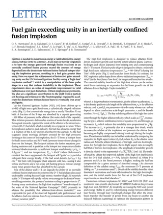
  • 1. LETTER doi:10.1038/nature13008 Fuel gain exceeding unity in an inertially confined fusion implosion ¨ O. A. Hurricane1, D. A. Callahan1, D. T. Casey1, P. M. Celliers1, C. Cerjan1, E. L. Dewald1, T. R. Dittrich1, T. Doppner1, D. E. Hinkel1, L. F. Berzak Hopkins1, J. L. Kline2, S. Le Pape1, T. Ma1, A. G. MacPhee1, J. L. Milovich1, A. Pak1, H.-S. Park1, P. K. Patel1, B. A. Remington1, J. D. Salmonson1, P. T. Springer1 & R. Tommasini1 Ignition is needed to make fusion energy a viable alternative energy source, but has yet to be achieved1. A key step on the way to ignition is to have the energy generated through fusion reactions in an inertially confined fusion plasma exceed the amount of energy deposited into the deuterium–tritium fusion fuel and hotspot during the implosion process, resulting in a fuel gain greater than unity. Here we report the achievement of fusion fuel gains exceeding unity on the US National Ignition Facility using a ‘high-foot’ implosion method2,3, which is a manipulation of the laser pulse shape in a way that reduces instability in the implosion. These experiments show an order-of-magnitude improvement in yield performance over past deuterium–tritium implosion experiments. We also see a significant contribution to the yield from a-particle self-heating and evidence for the ‘bootstrapping’ required to accelerate the deuterium–tritium fusion burn to eventually ‘run away’ and ignite. At the National Ignition Facility (NIF), 192 lasers deliver up to 1.9 MJ of light into a gold hohlraum, a cylindrically shaped radiation cavity (Fig. 1), that converts the energy into a nearly Planckian X-ray bath. A fraction of the X-rays are absorbed by a capsule generating ,100 Mbar of pressure in the ablator (the outer shell of the capsule). This ablation pressure, delivered as a series of weak shocks, accelerates the capsule inwards. Against the inside of the ablator is the deuterium– tritium (D–T) fuel shell, which is initially in a cryogenic ice state. When the implosion achieves peak velocity, the fuel has a kinetic energy that is a fraction of the X-ray energy absorbed by the capsule. As the fuel stagnates (stops moving), abruptly arrested by the high pressures forming at the centre of the implosion, the D–T forms a hotspot from the fuel’s inner surface and PdV work (pressure times volume change) is done on the hotspot. The hotspot initiates the fusion reactions, producing neutrons and a-particles as the hotspot ion temperature climbs to many kiloelectronvolts. At sufficient hotspot areal density, (rr)hs . 0.3 g cm22, and ion temperature, Tion . 4 keV (where Boltzmann’s constant has been suppressed), the hotspot will ‘ignite’ as a-particles redeposit their energy locally. If the fuel areal density, (rr)fuel . 1 g cm22 the burn will propagate (heat adjacent cold fuel, causing it also to fuse and burn) and a run-away self-heating process releases energy many times greater than that absorbed by the capsule. Mix of the ablator and D–T can degrade the ability of an inertially confined fusion implosion to compress the D–T fuel and can also cause undesirable cooling because high-atomic-number (high-Z) materials in the D–T hotspot will rapidly radiate away energy in the form of bremsstrahlung emission, the power of emission scaling in proportion to Z2. Among many motivations, the high-foot implosion2,3 was developed in the wake of the National Ignition Campaign4,5 (NIC) primarily to address the possibility that ablation-front-driven instability6,7 was responsible for part of the observed degraded yield performance1 and the ablator–fuel mix inferred from X-ray emissions in combination with primary neutron yield8,9. 1 The high-foot implosion is designed to reduce ablation-frontdriven instability growth and thereby inhibit ablator plastic (carbon– hydrogen and silicon dopants) from mixing into and contaminating the D–T hotspot. The laser pulse shape is designed to obtain a relatively high hohlraum radiation temperature (Trad < 90–100 eV) during the ‘foot’ of the pulse (Fig. 1) and launches three shocks. In contrast, the NIC implosion pulse shape drives a lower radiation temperature (Trad < 60 eV) in the foot (hence ‘low-foot’) for longer and launches four shocks. The essential stability benefits of the high-foot scheme can be understood from examining an expression for the linear growth rate of the ablation-driven Rayleigh–Taylor instability10 sffiffiffiffiffiffiffiffiffiffiffiffiffiffi kg {b2 ðFr, nÞkva cAÀRTI ~a2 ðFr, nÞ ð1Þ 1zkLr where k is the perturbation wavenumber, g is the ablator acceleration, Lr is the density gradient scale length of the ablation front, va is the ablation velocity, and a2 and b2 are parameters of order unity whose exact values depend on a heat À Á conduction scale-length parameter, n, and the Froude 2 number, Fr~va gLr . The key stabilizing effects of the high-foot drive 9=10 enter through the higher ablation velocity, which scales as Trad , increasing the b2kva ablative stabilization term of equation (1), and throughffiffiffiffiffi p an increase in Lr, which reduces the instability term proportional to kg . The increase in Lr is primarily due to a stronger first shock, which increases the adiabat of the implosion and prevents the ablator from becoming so highly compressed (risking break-up) during the implosion. The enhanced stability can be further understood by comparing the respective in-flight aspect ratios (Rin/DR, where Rin is the ablator inner radius and DR is the ablator thickness) of the high- and low-foot implosions: for the high-foot implosion, the in-flight aspect ratio is roughly half that of the low-foot implosion—the amplitude of instability growth pffiffiffiffiffiffiffiffiffiffiffiffiffiffiffi is directly related to the exponential of Rin =DR 2 (ref. 11). The tradeoff made to obtain the improved stability of the high-foot implosion is that the D–T fuel adiabat, a 5 P/PF (usually denoted a), where P is pressure and PF is the Fermi pressure, is higher, making the fuel less compressible for a given amount of absorbed energy. (An alternate definition of the adiabat using Pcold, the minimum D–T pressure at 1000 g cm23, is sometimes used12.) Details of the stability benefits, other theoretical motivations and trade-offs involved in the high-foot implosion, and the initial results from the first set of five D–T implosion experiments are described elsewhere2,3. Deuterium–tritium implosions N130927 and N131119 (NIF shot number in year–month–day format YYMMDD) build on the previous high-foot shot, N1308123, by modestly increasing the NIF laser power and energy (Table 1) and by redistributing energy between different laser beams, through laser wavelength changes that affect the crossbeam transfer (the transfer of power from one beam to another via induced Brillouin scattering), to optimize the illumination pattern in Lawrence Livermore National Laboratory, PO Box 808, Livermore, California 94551, USA. 2Los Alamos National Laboratory, Los Alamos, New Mexico 87545, USA. 0 0 M O N T H 2 0 1 4 | VO L 0 0 0 | N AT U R E | 1 ©2014 Macmillan Publishers Limited. All rights reserved
  • 2. RESEARCH LETTER a b Inner cone Shot N130927 23.5° 30° 23.5° 44.5° 30° 44.5° 50° 44.5° 50° Outer cone D–T ice layer 44.5° 50° 2.263 mm CH ablator graded 2% Si doped Cryogenic cooling ring c Au hohlraum 300 N130927 3 shock Trad (eV) 200 Laser entrance hole N110914 4 shock High foot 100 Low foot 0.0 0.0 Laser quads 5.0 10.0 15.0 20.0 t (ns) Figure 1 | Indirectly driven, inertially confined fusion target for NIF. a, Schematic NIF ignition target showing a cut-away of the gold hohlraum and plastic capsule with representative laser bundles incident on the inside surface of the hohlraum. b, X-ray image of the actual capsule for N130927 with D–T fuel layer and surrounding CH (carbon–hydrogen) plastic ablator. c, X-ray radiation drive temperature versus time for the NIC low-foot implosion and the post-NIC high-foot implosion. the hohlraum13–16. Although the hotspot shape changes that result from these wavelength changes can be predicted to some extent17, in practice the precise wavelengths needed to achieve the desired (that is, round) shape are found empirically. For N130927, the choice of ˚ l23.5 2 l30 5 0.7 A between the 23.5u and 30.0u inner-cone beams was ˚ chosen for azimuthal symmetry control, with Dl23.5–outer 5 9.2 A and ˚ Dl30–outer 5 8.5 A (the respective laser wavelength differences between the 23.5u and 30u inner-cone beams and the outer-cone beams) used for equatorial symmetry control (see Fig. 1 for beam angles). For N131119, ˚ ˚ Dl23.5–outer 5 9.5 A and Dl30–outer 5 8.8 A. These wavelength choices were critical for keeping the hotspot shape under control as the implosion was pushed to higher velocities, because previous experiments had already shown the tendency for the hotspot to deform into an oblate toroidal shape when laser power was increased3. There are limits to the amount of control that can be exerted over the hotspot shape just through wavelength changes alone, and physical changes to the hohlraum may also be required in future experiments to maintain hotspot (and fuel) shapes that will achieve the desired results. We used a gold hohlraum of 5.75-mm diameter and 9.425-mm length, which are typical values in most high-foot cryogenic D–T implosion experiments (Fig. 1). The same hohlraum geometry was used during the NIC for most of the low-foot shots. As is typical for the high-foot series, the hohlraum was filled with helium gas of 1.6 mg cm23 density (as compared with 0.96 mg cm23 for the NIC), the purpose of which is to restrict and delay ingress of gold plasma from the inside wall of the hohlraum, which can impede laser beam propagation. The plastic capsule at the centre of the hohlraum for N130927 and N131119 respectively had outer-shell radii of 1.1315 and 1.1241 mm and inner-shell radii of 0.9365 and 0.9303 mm (Fig. 1). Layered on the inner surface of the capsule shell for N130927 and N131119 were 71.4 Table 1 | Measured and derived implosion performance metrics Quantity Y13–15 (neutron) Tion (keV) D–T Tion (keV) D–D DSR (%) tx (ps) P0x, P0n (mm) P2/P0x P3/P0x P4/P0x Ytotal (neutron) Efusion (kJ) rhs (mm) (rr)hs (g cm22) Ehs (kJ) Ea (kJ) EDT,total (kJ) Gfuel TW N131119425MJ 1:9 TW N130927390MJ 1:8 N13092725 N13092726 N130927 (sim.) (5.2 6 0.097) 3 1015 5.0 6 0.2 4.3 6 0.2 4.0 6 0.4 152.0 6 33.0 35.8 6 1.0, 34 6 4 20.34 6 0.039 0.015 6 0.027 20.009 6 0.039 6.1 3 1015 17.3 36.6 0.12–0.15 3.9–4.4 2.2–2.6 8.5–9.4 1.8–2.0 (4.4 6 0.11) 3 1015 4.63 6 0.31 3.77 6 0.2 3.85 6 0.41 161.0 6 33.0 35.3 6 1.1, 32 6 4 20.143 6 0.044 20.004 6 0.023 20.05 6 0.023 5.1 3 1015 14.4 35.5 0.12–0.18 3.5–4.2 2.0–2.4 10.2–12.0 1.2–1.4 — — — — — — — — — — — 34.4–42.3 0.13–0.19 3.7–5.5 2.0–2.4 10.0–13.9 1.04–1.44 — — — — — — — — — — — 35.7–36.0 0.1–0.14 3.71–4.56 2.0–2.5 10.92–11.19 1.28–1.31 7.6 3 1015 4.2 3.9 4.1 137 32 — — — 8.9 3 1015 25.1 32.2 0.15 4.1 2.8 13.4 1.9 Lines 1–9 for columns 2 and 3 are directly measured quantities; others are derived from the data. Columns 4–6 show results from two data-driven models and simulation, respectively. 2 | N AT U R E | VO L 0 0 0 | 0 0 M O N T H 2 0 1 4 ©2014 Macmillan Publishers Limited. All rights reserved
  • 3. LETTER RESEARCH b 0 20 –50 10 0 –50 –50 0 0 x (μm) 50 100 100 N130927 polar view Kapton channel 40 y (μm) 50 0 20 –50 –100 –100 10 –50 0 x (μm) 50 100 –50 0 (μm) x (μm) 50 0 y (μm) 20 20 10 z (μm) 0 15 –10 –20 10 –50 5 –50 0 x (μm) 50 −100 100 −50 0 50 100 0 50 x (μm) 100 N131119 equatorial x, 100 neutron image um 13–17-MeV neutrons 50 6–12-MeV neutrons Reconstructed shape for N131119 20 0 –100 –100 –100 –20 25 N131119 polar view Kapton channel 0 –50 –20 0 x (µm) 20 100 50 30 y (μm) 100 –50 –100 –100 0 –100 N130927 equatorial 100 neutron image 13–17-MeV neutrons 50 6–12-MeV neutrons 30 20 20 10 z (μm) 0 (μ –10 15 –20 10 –30 – 25 50 5 5 –100 –100 d Reconstructed shape for N130927 N131119 equatorial view Kapton channel y (μm) 30 50 z (μm) c 100 N130927 equatorial view Kapton channel z (μm) (μm) 100 z (μm) a 0 –50 –20 0 x (μm) 20 –100 –20 0 y (μm) 20 −100 −50 Figure 2 | X-ray and neutron images of the hotspot at bang-time. a, Equatorial (side-on) and polar (top-down) views of the hotspot shape for N130927. Kapton is the filter material in the imaging system that allows transmission of X-rays with energies of more than 6 keV. b, As in a, but for N131119. In these X-ray images, the contour shown in white is taken at the 17%-peak-brightness level (the colour scales show the brightness in arbitrary units) and is used to obtain a description of the shape in Legendre modes (equatorial view) and Fourier modes (polar view). c, Three-dimensional reconstructions of the hotspots. d, Superposition of direct (13–17 MeV) and down-scattered (6–12 MeV) neutron images from N130927 and N131119. (X-ray image analysis courtesy of N. Izumi, S. Khan, T. Ma and A. Pak of the NIF Shape Working Group; neutron image analysis courtesy of D. Fittinghoff, G. Grim, N. Guler and F. Merrill of the NIF Neutron Imaging System Working Group.) and, respectively, 69.3 mm of cryogenic D–T ice that was held at 0.8 K below its triple point for a shot temperature of 18.6 K, like all high-foot D–T shots. This ‘mini-quench condition’ generally produces an ice layer with fewer ice cracks than that produced by a full quench18. Characterization of the capsule surface showed a roughness typical of implosion capsules for NIF, and characterization of the D–T ice showed a roughness well within requirements. The very high quality of the D–T ice layer on N130927 was probably not a significant factor in its performance because the third-best shot on the NIF (N130812) had an ice layer that was somewhat worse (with greater surface roughness) than average. The quality of the D–T layer for N131119 was between the qualities of the layers for N130812 and N130927. Table 1 shows the key measurements and performance metrics for NIF shots N130927 and N131119. Key measured quantities are the neutron yield, Y13–15, in the 13–15-MeV energy band around the characteristic 14.1-MeV D–T fusion neutron energy; the burn-averaged ion temperature, Tion; the neutron and X-ray burn widths, respectively tn and tx; the down-scatter ratio (DSR); and the time of peak neutron brightness, or ‘bang-time’, tb. On the NIF, Y13–15 is an average of many diagnostics, including four neutron time-of-flight (NToF) detectors19, numerous radiochemical activation measurements20 and a magnetic recoil spectrometer21. The temperature Tion is directly related to the temporal spread obtained from the full-width at half-maximum of the NToF detectors. A temporal c-ray history gives tn (for the high-foot experiments, tx and tn are consistent to within their errors). The DSR comes from measuring, via NToF and the magnetic recoil spectrometer, the number of neutrons scattered into the energy range 10– 12 MeV, and is directly related to the areal density of the cold D–T fuel, (rr)fuel 20.3f 3 DSR (where f depends upon the amount of ablator mass remaining but is typically 0.95 6 0.05 (ref. 21 and B. K. Spears, personal communication)). Other diagnostics such as X-ray imaging and neutron imaging (Fig. 2) give information on the shape of the implosion. In what follows, we will use the aforementioned observables, which are measured over the duration of the fusion burn, to infer the amount of energy that was deposited into the D–T (both fuel and hotspot), to make a comparison with the amount of energy generated from fusion. The details of the analysis will focus on N130927; the results for N131119, which exceeded the performance of N130927, are quoted in Table 1. The analysis outlined in this letter uses an essentially onedimensional ‘onion-skin’ picture with a hotspot of uniform density and temperature surrounded by the fuel (with Gaussian or uniform radial density profile), although the observed three-dimensional hotspot shape information is used to obtain the hotspot volume. Also, an assumption of approximately equal ion and electron temperatures, Tion Te, is made and can be justified post hoc using an expression for the electron–ion collision time after the hotspot density is obtained. Analytical and simulation results based on less simplified assumptions are also quoted in Table 1 for comparison with what is detailed below. By analysing the observed hotspot shape (Fig. 2) in terms of Legendre modes (equatorial view, lines 6–9 of Table 1) and Fourier modes (polar view), where the hotspot perimeter, as defined by the 17%-of-peakbrightness contour, is given by # ? X P‘ Rhs ðhÞ~P0 1z P‘ ðcos hÞ ð2Þ P0 ‘~2 where P‘ (cos h) is the Legendre function, we obtain the hotspot volume, Vhs (Methods), and the effective spherical radius, rhs 5 (3Vhs/4p)1/3. (We note that there is no absolute reference for the X-ray or neutron images, and so mode ‘ 5 1 is not included in the shape description. However, ‘ 5 1 and m 5 1 motions can be obtained from the NToF detectors.) The total neutron yield, Ytotal, can be calculated from Ytotal 5 Y13–15exp(4DSR), which accounts for the neutrons produced but then scattered out of the measured 13–15-MeV energy band by the cold and dense D–T fuel. Because for D–T fusion reactions the energy per fusion is known (14.1 MeV per neutron and 3.5 MeV per a-particle), Efusion, the total fusion energy produced, can be calculated from Ytotal. From the measured Tion, the D–T reaction rate per unit volume, Æsvæ, can be calculated using standard formulae22 (Methods). For N130927, Æsvæ 5 4.75 3 10218–1.03 3 10217 cm3 s21 The range of values is driven by the measurement uncertainty in Tion. The reported Tion values are actually averages over several detectors. The observed spread in the individual detector Tion interpretations indicates some motional broadening contribution, which suggests that the lower temperature is more representative of the thermal temperature. Throughout this Letter, the uncertainty ranges given for values for all quoted quantities are driven by the uncertainty in Tion. For a 50:50 D–T mix the fusion power density is _DT ~7:04| 10{13 n2 hsvi in joules per cubic centimetre per second, where n is the yet-unknown number density of the fusing region. From Efusion, Vhs and 0 0 M O N T H 2 0 1 4 | VO L 0 0 0 | N AT U R E | 3 ©2014 Macmillan Publishers Limited. All rights reserved
  • 4. RESEARCH LETTER tx the hotspot number density can be calculated: sffiffiffiffiffiffiffiffiffiffiffiffiffiffiffiffiffiffiffiffiffiffiffiffiffiffiffiffiffiffiffiffiffiffiffiffiffiffiffiffiffiffiffiffi Efusion n~ 7:04|10{13 hsviVhs tx For N130927, n 5 8.1 3 1024–1.2 3 1025 cm23, a value that also provides the hotspot mass density (assuming a pure D–T hotspot, with average atomic mass number A~2:5 for D–T), rhs 5 34–50 g cm23; the hotspot mass, mhs 5 rhsVhs 5 6.4–9.4 mg; and the areal density, (rr)hs (Table 1). A number of quantities describing the implosion energetics now straightforwardly follow. The hotspot pressure can be obtained from Phs ~ðZz1Þrhs Tion =A (Z~1 for D–T), yielding Phs 5 126–152 Gbar. The hotspot energy is then Ehs ~(3=2)Phs Vhs (Table 1). The fraction, fa, of a-particle energy deposited into the hotspot can be calculated from a classic formula23 1 1 Ãz fa ~1{ Â Â Ã3 4 ðrr Þhs rla 160 ðrr Þhs rla where the a-particle stopping range can be found from24 5=4 rla ~ 0:025Te ð3Þ 5=4 1z0:0082Te in base units of centimetres, grams, and kiloelectronvolts. For N130927, fa 5 0.68–0.82. The energy deposited in the hotspot by a-particles is Ea 5 faEfusion/5, recalling that one-fifth of the D–T fusion energy is emitted in the form of a-particles (the remaining a-particle energy is deposited into the cold fuel). We note that, using the values found in Table 1, Ea/Ehs 0.56. These energies fully describe the hotspot, but part of the implosion energy was used to compress the remaining cold D–T fuel and so we must examine the fuel to get a full picture of the implosion energy balance. Because the D–T hotspot is formed by ablating the inner surface of the cold D–T fuel as electron conduction transports heat from the forming hotspot into the fuel, we can calculate the amount of D–T fuel remaining after the hotspot has formed because we know the initial amount of D–T ice layered onto the inside of the capsule, m0 5 186 mg (for N130927): mfuel 5 m0 2 mhs 5 176–179 mg. The cold D–T fuel mass forms a shell surrounding the hotspot with volume À3 Á 3 Vfuel ~(4p=3) rout {rhs , where rout is the unknown outer fuel radius. Ð Because mfuel ~4p rfuel r2 dr and the measured DSR provides a way Ð to obtain the fuel density, rfuel, from ðrr Þfuel ~ rfuel dr, by assuming a fuel profile we can solve for both the fuel layer thickness, rout 2 rhs, and density rfuel (Methods). We find that rffiffiffiffiffiffiffiffiffiffiffiffiffiffiffiffiffiffiffiffiffiffiffiffiffiffiffiffiffi mfuel 2 rout {rhs ~2s~ {rhs {rhs ð4Þ 2pðrr Þfuel with a Gaussian density profile exp½{(r{r0 )2 =2s2 Š pffiffiffiffiffi 2ps where r0 is the radius of peak fuel density. For N130927, rout 2 rhs 5 14.7–15.3 mm, rfuel 5 385–402 g cm23 and Vfuel 5 (3.0–3.2) 3 105 mm3. The fuel outer radius from these arguments, rout 5 50.8 mm (at 50% rfuel), is close to that obtained directly from the down-scattered neutron image (Fig. 2), where P0 5 55.4 mm (at 17% of maximum intensity). By this time of peak compression, the D–T fuel density has increased by a factor of more than 1,500. The fuel density is not required for calculating the fuel energy, but it can be used to estimate the adiabat of the fuel (at bang-time) assuming that the cold fuel and the hotspot are isobaric 5=3 (Pfuel Phs), in which case we find that a~Pfuel =PF Phs =0:0021rfuel 5 2.9–3.3 for N130927—the fuel adiabat in flight is lower than this range of values. The fuel density is also needed to calculate the X-ray losses through the fuel. As the hotspot is compressed to high temperatures, the primary energy loss mechanism is bremsstrahlung X-ray emission because the D–T hotspot is optically thin to these X-rays. The bremsstrahlung energy loss is calculated to be24 pffiffiffiffiffi Ebrems (kJ)~5:34|10{34 n2 Te Vhs tx hs r(r)~(rr)fuel in base units of centimetres, kiloelectronvolts and seconds. For N130927, Ebrems 5 2.3–4.5 kJ, the low end of which is nearly equivalent to the 15 Self-heating yield/ compression yield 20 1.5 1.0 0.5 N130501 Yield from fuel compression N131119 N130927 N130812 Yield from self-heating Energy delivered to D–T fuel N130710 0.1 0.2 0.3 0.4 0.5 0.6 0.7 0.8 GLC 10 − Yield (kJ) 0 0 High foot Low foot High foot 5 0 110608 110615 110620 110826 110904 110908 110914 111103 111112 111215 120126 120131 120205 120213 120219 120311 120316 120321 120405 120412 120417 120422 120626 120716 120720 120802 120808 120920 130331 130501 130530 130710 130802 130812 130927 131119 Low foot Shot number Figure 3 | Yield and energetics metrics for shots on the NIF. Total fusion yield is plotted versus shot number (that is, time). Shots 110608–130331 are low-foot shots. Shots 130501–131119 are high-foot shots. The bars showing total yield are broken into components of yield coming from a-particle selfheating and yield coming from compression. The black dashes denote the energy delivered to the D–T (fuel plus hotspot) with error bars (black vertical lines, 1s) as calculated from the model of ref. 25. The plot shows that, even with the uncertainty in our results, shots 130927 and 131119 both yielded more fusion energy than was delivered to the D–T. Inset, ratio of self-heating yield to compression yield versus generalized Lawson criterion (GLC). All error bars, 1s. 4 | N AT U R E | VO L 0 0 0 | 0 0 M O N T H 2 0 1 4 ©2014 Macmillan Publishers Limited. All rights reserved
  • 5. LETTER RESEARCH a-particle energy deposited. To examine whether or not these X-rays can escape the dense cold fuel, we can calculate the optical depth of the cold D–T fuel from tfuel 5 rfuelkDT(rout 2 rhs) using a simple D–T opacity model, kDT (g cm22) 5 0.352rfuel(hn)23.3[1 2 exp(2hn/Te)]. We find that for X-ray energies of hn Tion Te, the D–T fuel layer is almost one optical depth, tfuel 5 0.32–0.66, implying that some bremsstrahlung X-rays deposit energy into the cold fuel whereas some escape. Electron conduction does not have a significant role in the total D–T energy loss from the cold fuel at stagnation, but is important for the hotspot energy loss. The cold fuel energy at stagnation now follows from the isobaric assumption, Efuel ~(3=2)Pfuel Vfuel 5 6.9–7.8 kJ (where we have overestimated the fuel internal energy because typically the outer edge of the fuel has not fully stagnated even at bang-time). The total energy delivered to the D–T by the implosion is then (Table 1) 1 1 EDT,total ~Ehs zEfuel z e{tfuel Ebrems { Ea ð5Þ 2 2 The factors of one-half in the radiation term and the a-particle energy deposition account for having only half the energy emitted or deposited at peak burn. This total D–T energy was calculated with quantities measured around bang-time, but it represents the kinetic plus internal energy in the fuel at peak velocity in the implosion. A crosscheck of EDT,total is provided from calculating the fuel kinetic energy, K, using a direct measurement of implosion velocity from an earlier high-foot ‘1DConA’ shot, N130409 (at 350 TW and 1.3 MJ of laser power and energy), where the peak ablator centre-of-mass velocity was measured to be 267 6 15 km s21, which is equivalent to a fuel velocity of 297 6 15 km s21 (the fuel being at smaller radius and convergence makes the velocity larger). Scaling the N130409-derived velocity to 0:41 the laser power of N130927 (implosion velocity, vimp !Plaser ) gives a 21 2 fuel velocity of vfuel 5 311 6 15 km s , and so K~(1=2)m0 vfuel ~9:0+ 0:9 kJ. The difference between K and EDT,total is the internal energy of the fuel at peak velocity plus the additional PdV work done by the ablator on the fuel during the deceleration. The total fuel energy gain, Gfuel 5 Efusion/EDT,total is now known and is 1.2–1.4 for N130927. For comparison, in Table 1 we also show results from other data-derived models of implosion energetics25,26 that are constructed in the spirit of the above analysis but which differ in some details. A conduction-limited temperature profile in the hotspot is added to the above development in one case25 and the other ‘detailed model’ case includes a three-dimensional, self-consistent physics model matched to the data26. To complement these analytic datadriven models, in Table 1 we also show the results from a full, onedimensional, radiation–hydrodynamics simulation27 of N130927, with a multifrequency X-ray drive that is calibrated to shock-timing and implosion trajectory data, without any mix model applied. The inferences from data and the computer simulation all indicate that Gfuel . 1. Moreover, we have demonstrated repeatability and improvement with the follow-on shot N131119. It should be understood, however, that Gfuel . 1 indicates only that the output fusion energy exceeds the energy deposited into the fuel. This is not the same as exceeding either the energy absorbed by the capsule (defined as the ablator shell plus D–T fuel), which absorbed ,150 kJ for N130927 and N131119, or the energy delivered by the laser to the target (defined as the hohlraum plus capsule), which was 1.8 MJ for N130927 and 1.9 MJ for N131119. Key yield and energy performance metrics are graphically illustrated in Fig. 3 for N131119, N130927 and all other D–T implosions carried out on the NIF since the summer of 2011. Using a key metric for ignition, the generalized Lawson criterion28 x 5 (Pt)/(Pt)ign (which is unity at ignition) we see (Fig. 3, inset) that for N131119 we are at the threshold of achieving yield doubling due to a-particle energy deposition. Because most of the quantities associated with inertially confined fusion that we seek to improve to achieve ignition scale as some positive power of stagnation pressure, near-term efforts focus on increasing the implosion speed and controlling the hotspot shape with the present fuel adiabat. As the implosion speed is increased, we will necessarily risk giving back some of the gains the high-foot implosion has made in terms of instability control. New strategies for the hohlraum will also be explored because at present hohlraum physics is limiting our ability to use the full power capability on the NIF while maintaining an acceptable hotspot shape (higher laser powers are the most direct way to increase implosion speed). Future efforts may involve more elaborate schemes to maintain control over ablator instability while recovering a lower adiabat for the fuel (for example ‘adiabat shaping’29) or also using an alternate ablator material. METHODS SUMMARY Formulae for the hotspot volume and the D–T reaction rate, and a discussion of fuel density profiles, are given in Methods. Neutron image shape coefficients are also given there. Online Content Any additional Methods, Extended Data display items and Source Data are available in the online version of the paper; references unique to these sections appear only in the online paper. Received 1 November 2013; accepted 7 January 2014. Published online 12 February 2014. 1. 2. 3. 4. 5. 6. 7. 8. 9. 10. 11. 12. 13. 14. 15. 16. 17. 18. 19. 20. 21. 22. 23. 24. 25. Edwards, M. J. et al. Progress towards ignition on the National Ignition Facility. Phys. Plasmas 20, 070501 (2013). Dittrich, T. R. et al. Design of a high-foot/high-adiabat ICF capsule for the National Ignition Facility. Phys. Rev. Lett. 112, LJ14108 (2014). Park, H.-S. et al. High-adiabat, high-foot, inertial confinement fusion implosion experiments on the National Ignition Facility. Phys. Rev. Lett. 112, LK13998 (2014). Lindl, J. D. Moses, E. I. Plans for the National Ignition Campaign (NIC) on the National Ignition Facility (NIF): on the threshold of initiating ignition experiments. Phys. Plasmas 18, 050901 (2011). Glenzer, S. H. et al. Cryogenic thermonuclear fuel implosions on the National Ignition Facility. Phys. Plasmas 19, 056318 (2012). Bodner, S. E. Rayleigh-Taylor instability and laser-pellet fusion. Phys. Rev. Lett. 33, 761–764 (1974). Gonchorov, V. N. Hurricane, O. A. Panel 3 Report: Implosion Hydrodynamics. Report LLNL-TR-562104 (Lawrence Livermore National Laboratory, 2012). Ma, T. et al. Onset of hydrodynamic mix in high-velocity, highly compressed inertial confinement fusion implosions. Phys. Rev. Lett. 111, 085004 (2013). Regan, S. P. et al. Hot-spot mix in ignition-scale inertial confinement fusion targets. Phys. Rev. Lett. 111, 045001 (2013). Betti, R., Goncharov, V. N., McCrory, R. L. Verdon, C. P. Growth rates of the Rayleigh-Taylor instability in inertial confinement fusion. Phys. Plasmas 5, 1446–1454 (1998). Lindl, J. Development of the indirect-drive approach to inertial confinement fusion and the target physics basis for ignition and gain. Phys. Plasmas 2, 3933–4024 (1995). Haan, S. et al. Point design targets, specifications, and requirements for the 2010 ignition campaign on the National Ignition Facility. Phys. Plasmas 18, 051001 (2011). Michel, P. et al. Tuning the implosion symmetry of ICF targets via controlled crossed-beam energy transfer. Phys. Rev. Lett. 102, 025004 (2009). Michel, P. et al. Symmetry tuning via controlled crossed-beam energy transfer on the National Ignition Facility. Phys. Plasmas 17, 056305 (2010). Moody, J. D. et al. Multistep redirection by cross-beam power transfer of ultrahighpower lasers in a plasma. Nature Phys. 8, 344–349 (2012). Callahan, D. A. et al. The velocity campaign for ignition on NIF. Phys. Plasmas 19, 056305 (2012). Marinak, M. M. et al. Three-dimensional HYDRA simulations of National Ignition Facility targets. Phys. Plasmas 8, 2275 (2001). Kozioziemski, B. J. et al. Deuterium-tritium layer formation for the National Ignition Facility. Fusion Sci. Technol. 59, 14–25 (2011). Glebov, V. Yu. et al. Development of nuclear diagnostics for the National Ignition Facility. Rev. Sci. Instrum. 77, 10E715 (2006). Bleuel, D. L. et al. Neutron activation diagnostics at the National Ignition Facility. Rev. Sci. Instrum. 83, 10D313 (2012). Gatu Johnson, M. et al. Neutron spectrometry – an essential tool for diagnosing implosions at the National Ignition Facility. Rev. Sci. Instrum. 83, 10D308 (2012). Bosch, H.-S. Hale, G. M. Improved formulas for fusion cross-section and thermal reactivities. Nucl. Fusion 32, 611–631 (1992). Krokhin, O. N. Rozanov, V. B. Escape of a-particles from a laser-pulse-initiated thermonuclear reaction. Sov. J. Quantum Electron. 2, 393–394 (1973). Atzeni, S. Meyer-ter-Vehn, J. The Physics of Inertial Fusion 32, 398 (Oxford Univ. Press, 2004). Patel, P. et al. Performance of DT layered implosions on the NIF. Bull. Am. Phys. Soc. 58, abstr. NO4.00001 (2013). 0 0 M O N T H 2 0 1 4 | VO L 0 0 0 | N AT U R E | 5 ©2014 Macmillan Publishers Limited. All rights reserved
  • 6. RESEARCH LETTER 26. Cerjan, C., Springer, P. T. Sepke, S. M. Integrated diagnostic analysis of inertial confinement fusion capsule performance. Phys. Plasmas 20, 056319 (2013). 27. Zimmerman, G. B. Kruer, W. L. Numerical Simulation of laser initiated fusion. Comments Plasma Phys. Control. Fusion 2, 85–89 (1975). 28. Betti, R. et al. Thermonuclear ignition in inertial confinement fusion and comparison with magnetic confinement. Phys. Plasmas 17, 058102 (2010). 29. Goncharov, V. N. et al. Improved performance of direct-drive ICF target designs with adiabat shaping using an intense picket. Phys. Plasmas 10, 1906–1918 (2003). Acknowledgements We thank P. Albright, J. Atherton, L. R. Benedetti, D. Bradley, J. A. Caggiano, R. Dylla-Spears, M. J. Edwards, W. H. Goldstein, B. Goodwin, S. Haan, A. Hamza, W. Hsing, P. Kervin, J. Kilkenny, B. Kozioziemski, O. Landen, J. Lindl, B. MacGowan, A. Mackinnon, N. Meezan, J. F. Meeker, J. Moody, E. Moses, D. Pilkington, T. Parham, J. Ralph, S. Ross, H. Robey, R. Rygg, B. Spears, R. Town, C. Verdon, A. Wan and B. Van Wonterghem, and the NIF operations, cryogenics and targets teams. We also thank V. Goncharov and J. Knauer for their advice, and R. Betti for bringing our attention to equation (3). Thanks also go to NIF’s external collaborators at GA (targets), LLE (diagnostics), the MIT Plasma Science and Fusion Center (magnetic recoil spectrometer diagnostic), CEA and AWE. This work was performed under the auspices of the US Department of Energy by Lawrence Livermore National Laboratory under contract no. DE-AC52-07NA27344. Author Contributions O.A.H. was lead scientist for the high-foot campaign, and performed two-dimensional stability modelling, and one-dimensional pre- and post-shot analysis. D.A.C. was lead scientist on hotspot shape and hohlraum strategies. D.T.C. was part of the D–T shot experiment team. P.M.C. performed VISAR data unfolds. C.C. performed three-dimensional ‘detailed model’ calculations. E.L.D. was lead experimenter for 1DConA (R(t) trajectory) tuning experiments and capsule re-emission (early-time symmetry) tuning experiments. T.R.D. performed initial one-dimensional capsule design, scoping, and one-dimensional pre- and post-shot simulations. T.D. was lead experimentalist on a 2DConA ablator shape experiment and was part of the D–T shot team. D.E.H. was the pulse shape design physicist and performed all two-dimensional integrated hohlraum-capsule simulations. L.F.B.H. was design physicist for keyhole (shock-timing) tuning experiments. J.L.K. was lead experimentalist for symcap (hotspot shape) tuning experiments. S.L. was lead experimentalist for the keyhole (shock-timing) tuning experiments. T.M. was lead experimentalist for several 2DConA ablator shape experiments, was part of the D–T shot team, and was lead experimentalist on shot N131119. A.G.M. was part of the 1DConA and D–T experimental teams. J.L.M. was design physicist for the re-emission experiment. A.P. was part of the D–T shot team. P.K.P. provided a hotspot model analysis and metrics plots. H.-S.P. was lead experimentalist on D–T implosion shots up to and including N130927. B.A.R. was overall lead on experiments. J.D.S. constructed model multifrequency sources normalized to tuning experiments, and performed oneand two-dimensional model scoping. P.T.S. provided a hotspot model analysis. R.T. provided 1DConA analysis and was shot experimentalist. Author Information Reprints and permissions information is available at www.nature.com/reprints. The authors declare no competing financial interests. Readers are welcome to comment on the online version of the paper. Correspondence and requests for materials should be addressed to O.A.H. (hurricane1@llnl.gov). 6 | N AT U R E | VO L 0 0 0 | 0 0 M O N T H 2 0 1 4 ©2014 Macmillan Publishers Limited. All rights reserved
  • 7. LETTER RESEARCH METHODS Hotspot volume formulae. Using equation (2) the volume is ð p ð Rhs ðhÞ Vhs ~2p 0 C0 1=3 Tion f~1{ R2 dR sin h dh 0 4 4 8 4 ~ pP03 z pP0P22 z pP23 z pP0P32 3 5 105 7 16 4 8 2 2 z pP2P3 z pP0P4 z pP22 P4 105 9 35 80 8 24 2 2 z pP2P4 z pP3 P4z pP43 z Á Á Á 693 77 1,001 A simple correction to this volume can be applied (by multiplying the above expression by the expression below) to include m-modes (azimuthal modes): 1z j~ 3 M2 2 3 M3 2 3 M4 2 z z 2 M0 2 M0 2 M0 z 3 M22 M4 cos½4ðw2 {w4 ÞŠ Á Á Á 4 M03 where w2 and w4 are phase offsets of m-modes 2 and 4, respectively. Deuterium–tritium reaction rate formulae. From ref. 22 hsvi~C1 f{5=6 j2 exp {3f1=3 j in cubic centimetres per second, where 2 3 C2 Tion zC4 Tion zC6 Tion 2 zC T 3 1zC3 Tion zC5 Tion 7 ion and C0 5 6.6610, C1 5 6.43413 10214, C2 5 1.51363 1022, C3 5 7.51893 1022, C4 5 4.60643 1023, C5 5 1.353 1022, C6 5 21.06753 1024 and C7 5 1.3663 1025 when Tion is expressed in kiloelectronvolts. Deuterium–tritium fuel density profile. Assuming a different density profile changes the form of equation (4), but changes the numerical value for the fuel thickness little. For example, assuming a top-hat distribution for the fuel yields qffiffiffiffiffiffiffiffiffiffiffiffiffiffiffiffiffiffiffiffiffiffiffiffiffiffiffiffiffiffiffiffiffiffiffiffiffiffiffiffiffiffiffi 1 2 3mfuel pðrr Þfuel {3rhs {3rhs =2 rout {rhs ~ 2 from which we obtain rout 2 rin 5 15.5–16.2 mm for N130927. The fuel density does show more sensitivity, being rfuel 5 (rr)fuel/(rout 2 rin) 5 457–478 g cm23 for pffiffiffiffiffi a top-hat distribution and rfuel ~ðrr Þfuel 2ps 5 385–402 for a Gaussian. The Gaussian profile assumption is more consistent with simulated fuel density profiles. The lower fuel density associated with the Gaussian profile increases the inferred fuel adiabat and decreases the fuel optical depth as compared with the uniform profile. The lower fuel optical depth makes the X-ray energy contribution to equation (5) larger; that is, it gives us a more conservative contribution to the total D–T energy. Neutron image shape analysis. For N130927, the Legendre mode shape coefficients for the down-scattered neutron image are P0 5 55 6 4 mm, P2/ P0 5 1% 6 5% and P4/P0 5 22%, and for the direct image P0 5 32 6 4 mm, P2/ P0 5 235% 6 5% and P4/P0 5 2%. For the N131119 down-scattered neutron image, P0 5 50 6 4 mm, P2/P0 5 0% 6 5% and P4/P0 5 2%, and for the direct image P0 5 34 6 4 mm, P2/P0 5 234% 6 5% and P4/P0 5 1%. ©2014 Macmillan Publishers Limited. All rights reserved