INTRODUCTION TO TERM USED IN NAVAL ARCHITECT
•Transferir como PPT, PDF•
7 gostaram•6,205 visualizações

these slides are helpfull for understanding the terms used in naval architect.

Recomendados
Mais conteúdo relacionado
Mais procurados
Mais procurados (20)
Destaque
Destaque (20)
Semelhante a INTRODUCTION TO TERM USED IN NAVAL ARCHITECT
Semelhante a INTRODUCTION TO TERM USED IN NAVAL ARCHITECT (20)
Mais de Indian Maritime University, Visakhapatnam
Mais de Indian Maritime University, Visakhapatnam (20)
Último
Último (20)
INTRODUCTION TO TERM USED IN NAVAL ARCHITECT
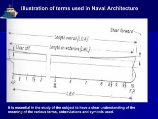
- 1. Illustration of terms used in Naval Architecture It is essential in the study of the subject to have a clear understanding of the meaning of the various terms, abbreviations and symbols used.
- 2. Definition of Principal terms used inDefinition of Principal terms used in Naval ArchitectureNaval Architecture Forward PerpendicularForward Perpendicular (FP) is a vertical line through(FP) is a vertical line through the inter-section of the load waterline and the stemthe inter-section of the load waterline and the stem contour.contour. AfAfter Perpendicularter Perpendicular (AP) is at where the aft side of(AP) is at where the aft side of the sternpost meets the load waterlinethe sternpost meets the load waterline oror if there isif there is no sternpost at the centre rudder stock.no sternpost at the centre rudder stock. Length between PerpendicularsLength between Perpendiculars (LBP) is the(LBP) is the horizontal distance between the forward and afterhorizontal distance between the forward and after perpendiculars.perpendiculars. AmidshipsAmidships (0 0) is the midway point between the(0 0) is the midway point between the perpendiculars.perpendiculars. MidshipMidship SectionSection is the transverse section of the shipis the transverse section of the ship at amidshipsat amidships..
- 3. Illustration of terms used in Naval Architecture
- 4. Definition of Principle terms used in NavalDefinition of Principle terms used in Naval ArchitectureArchitecture Breath MouldedBreath Moulded (B mld) is measured at amidship and is the maximum(B mld) is measured at amidship and is the maximum breadth over the frames.breadth over the frames. Depth MouldedDepth Moulded (D mld) is the vertical distance at amidships top of keel to(D mld) is the vertical distance at amidships top of keel to the top of the deck beam at sidethe top of the deck beam at side oror underside of deck plating at the shipunderside of deck plating at the ship side:side: Draught MouldedDraught Moulded (H mld) is the distance of the top of the keel below the(H mld) is the distance of the top of the keel below the waterline.waterline. DraughtDraught (H)(H) is the distance of the lowest point of the keel below theis the distance of the lowest point of the keel below the waterline.waterline. Moulded Base Line.Moulded Base Line. This is a horizontal line which passes through the topThis is a horizontal line which passes through the top of the keel at amidshipsof the keel at amidships Sheer.Sheer. The longitudinal curvature given to decks‘The longitudinal curvature given to decks‘ Camber.Camber. This is the curvature given to a deck transversely. The camberThis is the curvature given to a deck transversely. The camber amidships is frequently one-fiftieth of the breadth (B) of the ship.amidships is frequently one-fiftieth of the breadth (B) of the ship.
- 5. Definition of Principal terms used in Naval ArchitectureDefinition of Principal terms used in Naval Architecture Rise of FloorRise of Floor is the rise of the bottom shell plating measured transversely amidshipsis the rise of the bottom shell plating measured transversely amidships at the moulded breadth line.at the moulded breadth line. Tumble-HomeTumble-Home. The fall in of the sides amidships.. The fall in of the sides amidships. FlareFlare.. The outward curvature of the forward sections above the waterline.The outward curvature of the forward sections above the waterline. RakeRake.. The departure from the vertical of any line in profile such as the stem.The departure from the vertical of any line in profile such as the stem. TrimTrim.. The longitudinal inclination of a ship is measured by difference between theThe longitudinal inclination of a ship is measured by difference between the draughts forward and aft. When the draughts are the same forward and aft the shipdraughts forward and aft. When the draughts are the same forward and aft the ship is said to be ("on an even Keel”). "Down by the head” when the draught forward isis said to be ("on an even Keel”). "Down by the head” when the draught forward is greater than aft. "Down by the stern” when the draught aft is greater.greater than aft. "Down by the stern” when the draught aft is greater. HeelHeel.. The inclination of the ship in the transverse direction measured in degrees.The inclination of the ship in the transverse direction measured in degrees. YawYaw.. The movement from the mean course of a ship in the horizontal plane,The movement from the mean course of a ship in the horizontal plane, measured in degrees.measured in degrees.
- 6. Definition of Principle terms used in Naval ArchitectureDefinition of Principle terms used in Naval Architecture Middle Line PlaneMiddle Line Plane.. Ships have only one symmetry, called theShips have only one symmetry, called the middle line plane and it is the principal plane of reference. Themiddle line plane and it is the principal plane of reference. The shape of the ship given by this plane is known as the profile.shape of the ship given by this plane is known as the profile. WaterplanesWaterplanes are planes at right angles to the middle line plane;are planes at right angles to the middle line plane; they are symmetrical about the middle line plane. Waterplanesthey are symmetrical about the middle line plane. Waterplanes looked at edge on in the profile are called waterlines.looked at edge on in the profile are called waterlines. Transverse PlanesTransverse Planes perpendicular to the middle line plane show theperpendicular to the middle line plane show the shape of vertical sections of the ship.shape of vertical sections of the ship. Freeboard.Freeboard. The vertical distance between the actual or permissibleThe vertical distance between the actual or permissible waterline and the upper surface at side of the deck to which it is towaterline and the upper surface at side of the deck to which it is to measuredmeasured
- 7. Definition of Principal terms used in Naval ArchitectureDefinition of Principal terms used in Naval Architecture Load Line MarkLoad Line Mark .. All merchant ships, with a fewAll merchant ships, with a few exceptions, must be marked with a load line. The upperexceptions, must be marked with a load line. The upper edge of this line indicates the maximum permissibleedge of this line indicates the maximum permissible draught. The load lines are set off amidships on bothdraught. The load lines are set off amidships on both sides of the ship, at specified distances below a decksides of the ship, at specified distances below a deck line. The standard markings for a cargo ship are asline. The standard markings for a cargo ship are as under:under: S = Summer T = TropicalS = Summer T = Tropical W = Winter F = FreshW = Winter F = Fresh WaterWater WNA = Winter North AtlanticWNA = Winter North Atlantic TF = Tropical Fresh WaterTF = Tropical Fresh Water The upper edge of the summer line, if continued passesThe upper edge of the summer line, if continued passes through the centre of the load line disc and is the basisthrough the centre of the load line disc and is the basis line.line.
- 8. Parallel Middle body Illustration of terms used in Naval Architecture
- 9. Definition of Principal terms used in Naval ArchitectureDefinition of Principal terms used in Naval Architecture Parallel Middle BodyParallel Middle Body.. The length over which the midshipThe length over which the midship section remains constant in area and shape.section remains constant in area and shape. Fore BodyFore Body.. The immersed body forward of the midshipThe immersed body forward of the midship section.section. AfterAfter BodyBody.. The immersed body aft of the midship section.The immersed body aft of the midship section. Entrance.Entrance. The immersed body forward of the parallel body.The immersed body forward of the parallel body. Run.Run. The immersed body aft of the parallel bodyThe immersed body aft of the parallel body
- 10. Illustration of terms used in Naval Architecture
- 11. Definition of Principal terms used in Naval ArchitectureDefinition of Principal terms used in Naval Architecture Lines PlanLines Plan.. The delineation of the ship's form in three views:The delineation of the ship's form in three views: The longitudinal elevation or profile which gives the generalThe longitudinal elevation or profile which gives the general outline of the ship, the position and sheer of the decks.outline of the ship, the position and sheer of the decks. The half-breadth plan shows the shape of the decks and theThe half-breadth plan shows the shape of the decks and the waterlines which are formed by the intersection of the surfacewaterlines which are formed by the intersection of the surface of the ship with horizontal planes.of the ship with horizontal planes. The body plan which shows the transverse sections. TheThe body plan which shows the transverse sections. The lines plan represents the moulded surface of the ship, that islines plan represents the moulded surface of the ship, that is the inside of shell plating. The accepted convention for thethe inside of shell plating. The accepted convention for the profile is to show the bow pointing to the right.profile is to show the bow pointing to the right.
- 12. SHIP MOTIONSSHIP MOTIONS Understanding the terms likeUnderstanding the terms like Heaving, Pitching Surging, Rolling, Yawing, etcHeaving, Pitching Surging, Rolling, Yawing, etc.. Heave z
- 13. 2.2 Nomenclature for typical hull structures2.2 Nomenclature for typical hull structures 1 Strength deck1 Strength deck platingplating 16 Side shell longitudinals16 Side shell longitudinals 2 Stringer plate2 Stringer plate 17 Longitudinal bulkhead17 Longitudinal bulkhead platingplating 3 Sheer strake3 Sheer strake 18 Longitudinal bulkhead18 Longitudinal bulkhead longitudinalslongitudinals 4 Side shell4 Side shell platingplating 19 Inner bottom plating19 Inner bottom plating 5 Bilge plating5 Bilge plating 20 Inner bottom longitudinals20 Inner bottom longitudinals 6 Bottom shell6 Bottom shell PlatingPlating 25 Deck transverse centre25 Deck transverse centre tanktank 7 Keel plate7 Keel plate 26 Bottom transverse centre26 Bottom transverse centre tanktank 8 Deck8 Deck longitudinallongitudinal 27 Deck transverse wing tank27 Deck transverse wing tank 9 Deck girders9 Deck girders 28 Side shell vertical web28 Side shell vertical web 10 Sheer strake10 Sheer strake longitudinallongitudinal 29 Longitudinal bulkhead29 Longitudinal bulkhead vertical webvertical web 11 Longitudinal11 Longitudinal bulkhead topbulkhead top strakestrake 30 Bottom transverse wing30 Bottom transverse wing tanktank 12 Bottom12 Bottom longitudinalslongitudinals 31 Cross ties31 Cross ties 13 Bottom13 Bottom girdersgirders 32 Transverse web face plate32 Transverse web face plate 14 Bilge14 Bilge longitudinalslongitudinals 33 Double bottom floor33 Double bottom floor 15 Longitudinal15 Longitudinal bulkhead lowerbulkhead lower 36 Hatch coamings36 Hatch coamings Figure 2: Single Hull Oil / Ore Carrier — Typical Transverse Section
- 14. Fig 5: Single Skin Bulk Carrier-Fig 5: Single Skin Bulk Carrier- Typical Cargo Hold StructuralconfigurationTypical Cargo Hold Structuralconfiguration
- 15. Figure 6: Single Skin Bulk Carrier — Typical Transverse SectionFigure 6: Single Skin Bulk Carrier — Typical Transverse Section
- 16. Figure 7: Bulk Carrier — Typical Transverse Watertight BulkheadFigure 7: Bulk Carrier — Typical Transverse Watertight Bulkhead