Dc motors
•
2 gostaram•324 visualizações

This document discusses direct current (DC) motors, including: 1) It introduces DC motors and explains their advantages over AC motors for certain applications. 2) It describes the basic working principle of DC motors, which involves a current-carrying conductor experiencing a force when placed in a magnetic field. 3) It discusses the different types of DC motors - shunt-wound, series-wound, and compound-wound - and explains their characteristics. 4) It provides equations for the voltage and power of DC motors and uses examples to demonstrate how to solve problems related to back EMF, speed, power input/output, and other motor parameters.

Recomendados
Mais conteúdo relacionado
Mais procurados
Mais procurados (20)
Semelhante a Dc motors
Semelhante a Dc motors (20)
Mais de Dr.Raja Masood Larik
Mais de Dr.Raja Masood Larik (20)
Último
Último (20)
Dc motors
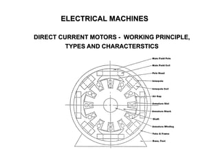
- 1. ELECTRICAL MACHINES DIRECT CURRENT MOTORS - WORKING PRINCIPLE, TYPES AND CHARACTERSTICS
- 2. 2 INTRODUCTION • For special applications such as in steel mills, mines and electric trains, it is advantageous to use d.c. motors. • Speed/ torque characteristics of d.c. motors are much more superior to that of a.c. motors. • D.C. motors are of three types viz., shunt-wound, series-wound, and compound-wound. D.C. Motor Principle • Operation of d.c. motor is based on the principle that when a current carrying conductor is placed in a magnetic field, the conductor experiences a mechanical force. • The direction of the force is given by Fleming’s left hand rule and magnitude is given by; F = BIL Newtons Lecture Notes by Dr.R.M.Larik
- 3. 3 WORKING OF D.C. MOTOR (i) The field magnets are excited developing alternate N and S poles (ii) All armature conductors under N-pole carry currents in one direction while all the conductors under S-pole carry currents in the opposite direction. Applying Fleming’s left hand rule, it is clear that force on each conductor is tending to rotate the armature in anticlockwise direction. When the motor terminals are connected to an external source of d.c. supply: Lecture Notes by Dr.R.M.Larik
- 4. 4 WORKING OF D.C. MOTOR Lecture Notes by Dr.R.M.Larik
- 5. 5 BACK OR COUNTER E.M.F. • When d.c. voltage V is applied in a shunt- wound motor, the field magnets are excited and current flows in armature conductors. • The driving torque acts on the armature which begins to rotate. • When the armature of a d.c. motor rotates, the armature conductors move through the magnetic field and electromotive force (e.m.f.) is induced in them • The induced e.m.f. acts in opposite direction to the applied voltage V (Lenz’s law), known as back or counter e.m.f. Eb which is always less than the applied voltage V, when the motor is in normal operation. • The applied voltage V has to force current through the armature against the back e.m.f. Eb. Lecture Notes by Dr.R.M.Larik
- 6. 6 BACK OR COUNTER E.M.F. (Contd) • The electric work done in overcoming and causing the current to flow against Eb is converted into mechanical energy developed in the armature. • Net voltage across the armature = V – Eb • If Ra is the armature resistance, then, armature current Ia = V − Eb Ra • Since V and Ra are usually fixed, the value of Eb will determine the current drawn by the motor. • If the speed of the motor is high, then back e.m.f. Eb (= PΦZN/60 A) is large and hence the motor will draw less armature current and vice-versa. Lecture Notes by Dr.R.M.Larik
- 7. 7 VOLTAGE EQUATION OF D.C. MOTOR Let in a d.c. motor V = applied voltage Eb = back e.m.f. Ra = armature resistance Ia = armature current Since back e.m.f. Eb acts opposite to the applied voltage V, the net voltage across the armature circuit is V- Eb. The armature current Ia is given by; Ia = V − Eb Ra or V = Eb + Ia Ra This is known as Voltage Equation of the d.c. motor. Lecture Notes by Dr.R.M.Larik
- 8. 8 POWER EQUATION OF D.C. MOTOR The voltage equation of d.c. motor is: V = Eb + Ia Ra On multiplying the above equation is by la, we get, V Ia = Eb Ia + Ia 2 Ra This is known as Power Equation of the d.c. motor. VIa = electric power supplied to armature (armature input) EbIa = power developed by armature (armature output) Ia 2 Ra = electric power wasted in armature (armature Cu loss) Out of the armature input, a small portion (about 5%) is wasted as Ia 2 Ra and the remaining portion EbIa is converted into mechanical power within armature. Lecture Notes by Dr.R.M.Larik
- 9. 9 NUMERICAL PROBLEMS Problem 1(a) A 220-V d.c. shunt motor has an armature resistance of 0.5 . If the full-load armature current is 20 A, find the back e.m.f. Solution: Supply voltage = 220 V DC, Ra = 0.5 , Ia = 20 A Back e.m.f. ? Eb = V – Ia Ra = 220 – 20 x 0.5 = 210 V Problem 1(b) A 440-V, shunt motor has armature resistance of 0.8 and field resistance of 200 . Determine the back e.m.f. when the motor is giving an output of 7.46 kW at 85 percent efficiency. Lecture Notes by Dr.R.M.Larik
- 10. 10 NUMERICAL PROBLEMS Problem 2(a) A 250 V shunt motor takes a load of 20 A. The shunt field and armature resistances are 200 and 0.3 respectively. Determine (i) value of back e.m.f. (ii) mechanical power developed in the armature. Solution: Supply voltage = 250 V DC, IL = 20 A, Rsh = 200 , Ra = 0.3 Ω Back e.m.f. ?, gross mechanical power of armature ? Ish = V Rsh = 250 200 = 1.25 A Ia = IL – Ish = 20 – 1.25 = 18.75 A Eb = V – Ia Ra = 250 – 18.75 x 0.3 = 244.4 V Lecture Notes by Dr.R.M.Larik
- 11. 11 NUMERICAL PROBLEMS (Contd.) Problem 2(a) Solution (Contd.) Mechanical power developed = Eb Ia = 244.4 x 18.75 = 4582.5 W Problem 2(b) A 25-kW, 250-V, d.c. shunt motor has armature and field resistances of 0.06 and 100 respectively. Determine the total armature power developed when the motor is taking 25 kW input. Problem 2(c) A 230 V motor has an armature circuit resistance of 0.6 . If the full load current is 30 A and a no load armature current is 4 A, find the change in the back e.m.f. from no load to full load. Lecture Notes by Dr.R.M.Larik
- 12. 12 NUMERICAL PROBLEMS (Contd.) Problem 3(a) A d.c. motor takes an armature current of 110 A at 480 V. The armature circuit resistance is 0.2 Ω. The motor has 6-poles and the armature is lap- wound with 864 conductors. The flux per pole is 0.05 Wb. Calculate the speed of motor. Solution: Supply voltage = 480 V DC, Ia = 110 A, Ra = 0. 2 , P = 6, A = P = 6 (for lap wound), Z = 864, Φ = 0.05 Wb/pole Speed of motor N ?, Back e.m.f. Eb = V – Ia Ra = 480 – 110 x 0.2 = 458 V Also Eb = Φ Z N 60 x P A 458 = 0.05 x 864 x N 60 x 6 6 N = 636 rpmLecture Notes by Dr.R.M.Larik
- 13. 13 NUMERICAL PROBLEMS (Contd.) Problem 3(b) A 4-pole, 500 V shunt motor has 720 wave-connected conductors in the armature. The full load armature current is 60 A and the flux per pole is 0.03 Wb. The armature resistance is 0.2 and the contact drop is 1 V per brush. Calculate full load speed of the motor. Problem 4(a) Find the no-load and full-load speeds for a four-pole, 220-V, and 20-kW, shunt motor having the following data: Field current = 5 A, armature resistance = 0.04 ohm, flux per pole = 0.04 Wb, number of armature-conductors = 160, two - circuit wave-connection, full load current = 95 A, No load current = 9 A Solution: Motor capacity = 20 kW, supply voltage = 220 V DC, Ish = 5 A, Ra = 0. 04 , Φ = 0.04 Wb/pole, Z = 160, P = 4, A = 2 (wave wound), IFL = 95 A, INL = 9 A No load speed No ?, Full load speed of motor N ?, Lecture Notes by Dr.R.M.Larik
- 14. 14 NUMERICAL PROBLEMS (Contd.) Problem 4(a) Solution (Contd.) Ia(NL) = INL – Ish = 9 – 5 = 4A Ia(FL) = IFL – Ish = 95 – 5 = 90 A At no load Back e.m.f. Ebo = V – Ia Ra = 220 – 4 x 0.04 = 219.84 V Also Eb = ∅ Z N 𝑜 60 x P A No = Eb x 60 x A P ∅ Z = 219.84 x 60 x 2 4 x 0.04 x 160 = 1030.5 r.p.m. Lecture Notes by Dr.R.M.Larik
- 15. 15 NUMERICAL PROBLEMS (Contd.) Problem 4(a) Solution (Contd.) At full load Back e.m.f. Eb = V – Ia Ra = 220 – 90 x 0.04 = 216.4 V Also Eb = ∅ Z N 60 x P A N = Eb x 60 x A P ∅ Z = 216.4 x 60 x 2 4 x 0.04 x 160 = 1014 r.p.m. Example 4(b): The counter e.m.f. of a shunt motor is 227 V, the field resistance is 160 and field current is 1.5 A. If the line current is 39 A, find the armature resistance. Also find the armature current when the motor is stationary. Lecture Notes by Dr.R.M.Larik
- 16. 16 TYPES OF D.C. MOTORS Shunt-Wound Motor • Shunt field windings are designed to produce the necessary Magnetomotive Force (mmf) by means of a relatively large number of turns of wire having high resistance. • Shunt field current is relatively small as compared to the armature current. Series-Wound Motor • The field windings is designed with much fewer turns than shunt field windings for the same mmf • Series field winding has a relatively small number of turns of thick wire and, therefore, will possess a low resistance. Lecture Notes by Dr.R.M.Larik
- 17. 17 TYPES OF D.C. MOTORS (Contd.) Compound-Wound Motor • It has two field windings; one connected in parallel with the armature and the other in series with it. • When the shunt field winding is directly connected across the armature terminals it is called short-shunt connection. • When the shunt winding is connected such that it shunts the series combination of armature and series field it is called long-shunt connection. Lecture Notes by Dr.R.M.Larik
- 18. 18 SPEED RELATIONS If a d.c. motor has initial values of speed, flux per pole and back e.m.f. as N1, ϕ1 and Eb1 respectively and the corresponding final values are N2, ϕ2 and Eb2, then, N1 Eb1 Φ1 and N2 Eb2 Φ2 N2 N1 = Eb2 Eb1 x Φ1 Φ2 (i) For a shunt motor, flux practically remains constant so that ϕ1 = ϕ2. N2 N1 = Eb2 Eb1 (ii) For a series motor, ϕ Ia prior to saturation. N2 N1 = Eb2 Eb1 x Ia1 Ia2 where Ia1 = initial armature current Ia2 = final armature current Lecture Notes by Dr.R.M.Larik
- 19. 19 NUMERICAL PROBLEMS Problem 5(a) A 250-V shunt motor runs at 1000 r.p.m. at no-load and takes 8A. The total armature and shunt field resistances are respectively 0.2 and 250 . Calculate the speed when loaded and taking 50 A. Assume the flux to be constant. Solution: Supply voltage = 250 V DC, No = 1000 r.p.m., Io = 8A, Ra = 0.2 , Rsh = 250 , I = 50 A Speed N ? (when loaded and taking 50 A) N No = Eb Ebo x Φ0 Φ Since Φo = Φ N No = Eb Ebo Ish = V Rsh = 250 250 = 1 A Lecture Notes by Dr.R.M.Larik
- 20. 20 NUMERICAL PROBLEMS (Contd.) Problem 5(a) Solution (Contd.): F.L. Armature current Ia = I – Ish = 50 – 1 = 49 A N. L. armature current Iao = Io – Ish = 8 – 1 = 7 A N. L. Back e.m.f. Ebo = V – Iao Ra = 250 – 7 x 0.2 = 248.6 V F. L. Back e.m.f. Eb = V – Ia Ra = 250 – 49 x 0.2 = 240.2 V N 1000 = 240.2 248.6 N = 966.2 r.p.m. Problem 5(b): A d.c. series motor operates at 800 r.p.m. with a line current of 100 A from 230-V mains. Its armature circuit resistance is 0.15 and its field resistance 0.1 . Find the speed at which the motor runs at a line current of 25 A, assuming that the flux at this current is 45 per cent of the flux at 100 A. Lecture Notes by Dr.R.M.Larik
- 21. 21 NUMERICAL PROBLEMS (Contd.) Problem 6 A 230-V d.c. shunt motor has an armature resistance of 0.5 and field resistance of 115 . At no load, the speed is 1,200 r.p.m. and the armature current 2.5 A. On application of rated load, the speed drops to 1,120 r.p.m. Determine the line current and power input when the motor delivers rated load. Solution: Supply = 230 V DC, Ra = 115 , Rsh = 0.5 , No = 1200 rpm, Iao = 2.5 A, N = 1120 rpm, Line current ?, Input power ? (at rated load) Ish = V Rsh = 230 115 = 2 A Back emf Ebo = V – Iao Ra = 230 – 2.5 x 0.5 = 228.75 V Back emf Eb = V – IaRa = 230 – Ia x 0.5 Lecture Notes by Dr.R.M.Larik
- 22. 22 NUMERICAL PROBLEMS (Contd.) Problem 6 Solution (Contd.) N No = Eb Ebo 1120 1200 = 230− Ia x 0.5 228.75 Ia = 33 A IL = Ia + Ish = 33 + 2 = 35 A Input power = V x IL = 230 x 35 = 8050 W Lecture Notes by Dr.R.M.Larik
- 23. 23 ARMATURE REACTION IN D.C. MOTORS • At no load the small armature current does not significantly affect the pole flux Φ1. • At full load the armature current creates a flux Φ2. • By superimposing Φ1 and Φ2 resulting flux Φ3 occurs. • As a result the flux density increases under the left half of the pole and decreases under right half producing two effects: a) Neutral zone shifts towards left resulting poor commutation with sparking at the brushes. b) Due to higher flux density at pole tip A saturation sets in. Lecture Notes by Dr.R.M.Larik
- 24. 24 ARMATURE REACTION IN D.C. MOTORS (Contd.) Correcting Measures • A set of commutating poles are place between the main poles which develop mmf equal and opposite to armature mmf • In the case of large d.c. motors undergoing rapid multiple operations the commutating poles do not adequately neutralize the armature mmf • To eliminate the problem special compensating winding are connected in series with the armature to produce mmf equal and opposite to armature mmf (on point to point basis). Lecture Notes by Dr.R.M.Larik
- 25. 25 COMMUTATION IN D.C. MOTORS • To produce unidirectional force (or torque) on the armature conductors, the conductors under any pole must carry the current in the same direction at all times. • When a conductor moves from the influence of N-pole to that of S-pole, the direction of current in the conductor must be reversed. This is termed as commutation. • Commutator and the brush gear in a d.c. motor causes the reversal of current in a conductor as it moves from one side of a brush to the other. Lecture Notes by Dr.R.M.Larik
- 26. 26 LOSSES IN A D.C. MOTOR Mechanical losses • The mechanical losses (friction and windage) vary as the cube of the speed of rotation of the d.c. motor • Since d.c. motors are generally operated at constant speed, mechanical losses are considered to be constant. Copper losses Armature Cu loss, field Cu loss, brush contact loss, Cu losses in interpoles (commutating poles) and compensating windings Iron losses or magnetic losses Since d.c. motors are generally operated at constant flux density and constant speed, the iron losses are nearly constant. Lecture Notes by Dr.R.M.Larik
- 27. 27 D.C. MOTOR CHARACTERISTICS Torque and Armature Current (Ta/Ia) It is the curve between armature torque Ta and armature current Ia of a d.c. motor and is known as electrical characteristic of the motor. Speed and Torque (N/Ta) It is the curve between speed N and armature torque Ta of a d.c. motor and is known as mechanical characteristic. Speed and Armature Current (N/Ia) It is the curve between speed N and armature current Ia of a d.c. motor and is very important characteristic as it is the deciding factor in the selection of the motor for a particular application. Lecture Notes by Dr.R.M.Larik
- 28. 28 CHARACTERISTICS OF SHUNT MOTORS ➢ Ta/Ia Characteristic • In a d.c. motor, Ta ϕ Ia • Since supply voltage of motor is constant, Ish is constant & flux Φ is also constant (neglecting armature reaction) Ta Ia • Hence Ta/Ia characteristic is a straight line passing through the origin • The shaft torque (Tsh) is less than Ta and is shown by a dotted line. • Very large current is required to start a heavy load, hence, a shunt motor should not be started on heavy load. Lecture Notes by Dr.R.M.Larik
- 29. 29 CHARACTERISTICS OF SHUNT MOTORS (Contd.) ➢ N/Ia Characteristic • The speed N of a d.c. motor is given by; N Eb Φ • The flux Φ and back e.m.f. Eb in a shunt motor are almost constant, hence, the speed of a shunt motor remains constant with the variation of armature current (line AB) • When load increases, Eb (= V- IaRa) and Φ decrease due to increase in armature resistance voltage drop and armature reaction • Eb decreases slightly more than Φ so the speed of the motor decreases slightly with load (line AC). Lecture Notes by Dr.R.M.Larik
- 30. 30 CHARACTERISTICS OF SHUNT MOTORS (Contd.) ➢ N/Ta Characteristic • The curve is obtained by plotting the values of N and Ta for various armature currents • The speed falls somewhat as the load torque increases. Conclusions (i) The shunt motor is a constant-speed motor as there is slight change in its speed from no-load to full load (ii) The starting torque is not high because Ta Ia Lecture Notes by Dr.R.M.Larik
- 31. 31 CHARACTERISTICS OF SERIES MOTORS ➢ Ta/Ia Characteristic • The armature current increases with the increase in the mechanical load • The flux in the field also increases • Upto magnetic saturation, ϕ Ia so that Ta Ia 2 • After magnetic saturation, Φ is constant so that Ta Ia • Thus upto magnetic saturation, the armature torque is directly proportional to the square of armature current. • In a d.c. motor, Ta Φ Ia Lecture Notes by Dr.R.M.Larik
- 32. 32 CHARACTERISTICS OF SERIES MOTORS (Contd.) ➢ N/Ia Characteristic • The speed N is given by; N Eb ϕ where Eb = V – Ia (Ra + Rse) • When the armature current increases, the back e.m.f. Eb decreases while the flux ϕ increases. • Neglecting the Ia(Ra + Rsc) drop, which is quite small under normal conditions, N 1 ϕ N 1 Ia upto magnetic saturation Lecture Notes by Dr.R.M.Larik
- 33. 33 CHARACTERISTICS OF SERIES MOTORS (Contd.) ➢ N/Ta Characteristic • Series motor develops high torque at low speed and vice-versa because an increase in torque requires an increase in armature current, which is also the field current. • The result is that flux is strengthened and hence the speed drops (as N 1 ϕ ) Conclusions • Series motor has a high starting torque • It is a variable speed motor and automatically adjusts the speed as the load changes. • It should never be started on no-load Lecture Notes by Dr.R.M.Larik
- 34. 34 CHARACTERISTICS OF COMPOUND MOTORS ➢ Ta/Ia Characteristic • As the load increases, the series field increases but shunt field strength remains constant. • Consequently, total flux is increased and hence the armature torque • Torque of a cumulative-compound motor is greater than that of shunt motor for a given armature current due to series field Lecture Notes by Dr.R.M.Larik
- 35. 35 CHARACTERISTICS OF COMPOUND MOTORS (Contd.) ➢ N/Ia Characteristic • The flux per pole increases with the increase in load • Consequently, the speed of the motor decreases as the load increases • When the load is added, the increased amount of flux causes the speed to decrease more than does the speed of a shunt motor. Lecture Notes by Dr.R.M.Larik
- 36. 36 CHARACTERISTICS OF COMPOUND MOTORS (Contd.) ➢ N/Ta Characteristic For a given armature current, the torque of a cumulative compound motor is more than that of a shunt motor but less than that of a series motor. Conclusions • Due to the presence of shunt field, the motor is prevented from running away at no-load. • Due to the presence of series field, the starting torque is increased. Lecture Notes by Dr.R.M.Larik
- 37. 37 COMPARISON OF THREE TYPES OF MOTORS • The speed regulation of a shunt motor is better than that of a series motor. • For a given armature current, the starting torque of a series motor is more than that of a shunt motor. • The starting torque of a cumulative compound motor lies between series and shunt motors • Both shunt and cumulative compound motors have definite no-load speed. • However, a series motor has dangerously high speed at no-load.Lecture Notes by Dr.R.M.Larik
- 38. 38 APPLICATIONS OF D.C. MOTORS ✓Shunt Motors (i) the speed is required to remain almost constant from no-load to full-load (ii) the load is to be driven at a number of speeds and any one of which is required to remain nearly constant Industrial use: Lathes, drills, boring mills, shapers, spinning and weaving machines etc. ✓Series Motors (i) large starting torque is required (ii) the load is subjected to heavy fluctuations and the speed is automatically required to reduce at high torques Industrial use: Electric traction, cranes, elevators, air compressors, vacuum cleaners, hair drier, sewing machines etc. Shunt motors are used where: Series motors are used where: Lecture Notes by Dr.R.M.Larik
- 39. 39 APPLICATIONS OF D.C. MOTORS ✓Compound Motors Compound motors are used where a fairly constant speed is required with irregular loads or suddenly applied heavy loads. Industrial use: Presses, shears, reciprocating machines etc. Lecture Notes by Dr.R.M.Larik