
Recomendados
Mais conteúdo relacionado
Mais procurados
Mais procurados (20)
Destaque
Destaque (19)
Semelhante a D0364017024
Semelhante a D0364017024 (20)
Último
Último (20)
D0364017024
- 1. The International Journal Of Engineering And Science (IJES) || Volume || 3 || Issue || 6 || Pages || 17-24 || 2014 || ISSN (e): 2319 – 1813 ISSN (p): 2319 – 1805 www.theijes.com The IJES Page 17 FPGA Implementation of System-on-chip (SOC) Architecture for Spacecraft Application 1, Kiran Kumar B.G , 2, Dr. Kaushik Bhattacharyya 1,2, Department of Electronics and Communication, CMRIT -------------------------------------------------ABSTRACT-------------------------------------------------------- The high performance and rich functionality is more preferable for consumer. This drives the semiconductor manufacturing industry to the integration of multiple complex components in a single chip. This is achieved by integrating all the components into a single chip. This paper is concerned with the design of SOC (system on chip) for detecting and correcting the error which may occur in the memory unit due to radiation in LEO (lower earth orbit) and due to stuck-at faults in memory unit in space station. The error free data is feed to the predestined processor using the serial communication protocol (UART) and perform its function specified in the data input which is sent from the ground station. The integration of SRAM (Static Random Access Memory), EDAC unit (Error Detection and Correction), Router and UART (Universal Asynchronous Receiver and Transmitter) performs the error detection and correction operation. The processor which is used outside the SOC performs the specified operation. The results are analyzed for SPARTAN3 and SPARTAN3E FPGA devices. This architecture using VIRTEX 5 FPGA device makes a trade-off between frequency and time delay with 48% increase in operating frequency and having a minimum time delay of about 5%. KEYWORDS : system on chip, lower earth orbit, EDAC unit, Static RAM, UART. --------------------------------------------------------------------------------------------------------------------------------------- Date of Submission: 09 June 2014 Date of Publication: 20 June 2014 --------------------------------------------------------------------------------------------------------------------------------------- I. INTRODUCTION The design and test engineers face various problems in a SOC design which uses multi-million gates. The common problems are signal integrity, huge power consumption and increase in testability challenges. In order to keep pace with the levels of integration available, design engineers have developed new methodologies and techniques to manage the increased complexity inherent in those large chips. One such emerging methodology is system-on-chip design. Thus semiconductor industry continued to make more improvements in the achievable density of very large-scale integrated (VLSI) circuits. In the past, the concept of SOC simply implied higher and higher levels of integration. That is transferring a system-on-board to a single chip containing digital logic, analog/mixed signal and RF blocks. The primary drivers for this direction were the reduction of power, smaller form factor and the lower overall cost. The SOC integrating more and more functionality in a single chip is existed as a trend by virtue of Moore' s Law, which states that the number of transistors on a chip will double every 18-24 months. For many improvements in the integrated Circuits (IC) industry is by increasing the integration level of SOC design has now become very crucial. Developments in microelectronics have revolutionized computer design. Integrated circuit technology has increased the number and complexity of the components that can fit on a chip. Consequently, this technology allows the building of low cost, special purpose, Peripheral devices to rapidly solve sophisticated problems The importance of reducing the size of the error detection and correction unit in SOC is further motivated by comparing the size of the error detection and correction unit on System-on-board (SOB) fabrication. The relative size of SOB more compared to the size of the SOC. In past days the error detection and correction unit was fabricated on SOB. This design uses more power consumption, cost and more area required compared to SOC design. Today, the size and cost of SOC is a significant part. This motivates the design of EDAC unit in the form of SOC.
- 2. FPGA Implementation Of System-on-Chip (Soc) Architecture for Spacecraft Application www.theijes.com The IJES Page 18 II. DESCRIPTION OF THE SYSTEM WITH BLOCK DIAGRAM An On-Board System (OBS) of a small Satellite is implemented in the form of a System-on-a-Chip (SOC). The System on-a-chip is build by coding in hardware description language (Verilog HDL). The resulting subsystem is the integration of SRAM, EDAC UNIT, UART and ROUTER which are designed. The Processor is placed at outside of the SOC. The Block Diagram of the design is shown in below Figure 1.3 Fig1: Block Diagram of SOC The input data is send from ground station to the space station is given as input to the SRAM. A single bit of the codeword can affect at most in memory chip regardless of the physical defect mode. In memory system there is a chance of stuck at faults. In space applications it is well known that in Low Earth Orbit (LEO) stored digital data suffers from SEUs in memory chips. These upsets are naturally induced by radiation. Bit-flips caused by SEUs are a well-known problem in memory chips and error detection and correction techniques have been an effective solution to this problem. For the secure transmission of data between the CPU, ROUTER and its local RAM, the program memory has generally been designed by applying the extended Hamming code in the error detection and correction unit so that the errors can be detected and corrected and the resultant output will be a error free data. The resultant error free data is fed to the processor, so that it will process the error free data and also collect all the on-board data signals and produce the resultant data output. 2.1 Extended hamming code For many applications a single error correcting code would be considered unsatisfactory, because it accepts all blocks received. A SEC-DED code safer and it is the level of correction and detection most often used in computer memories. The Hamming code can be converted to a SEC-DED code by adding one check bit, which is a parity bit (let us assume even parity) on all the bits in the SEC code word. This code is called an extended Hamming code. The bits representation of extended hamming code has given in the table 2.1 Table 2.1 Hamming code bits representation DATS BITS CHECK BITS TOTAL BITS 1 3 4 4 4 8 8 5 13 16 6 22 32 7 39 III ARCHITECTURAL DESIGN The architecture of SOC consists of Encoder unit, SRAM (FIFO) unit, Decoder unit, UART and Router unit. The Processor unit, buzzer and the cooling fan are implemented outside the SOC. The proposed architecture level of SOC has shown in the Figure 2.
- 3. FPGA Implementation Of System-on-Chip (Soc) Architecture for Spacecraft Application www.theijes.com The IJES Page 19 Fig 2: Architectural design of SOC 3.1 Encoder The encoder is the first block which comes within the EDAC unit. It receives the given data input bits and generates the parity bits and then generates then output which is a combination of both input data bits and parity bits. The 16-bits of input data bits are given as an input to the encoder, using these input data bits the parity generator will generate the parity bits using formula Parity Generator The parity generator takes the data input bits and generate the parity bits as follows. P0 = D0 ^ D1 ^ D3 ^ D4 ^ D6 ^ D8 ^ D10 ^ D11 ^ D13 ^ D15 P1= D0 ^ D2 ^ D3 ^ D5 ^ D6 ^ D9 ^ D10 ^ D12 ^ D13 P2= D1 ^ D2 ^ D3 ^ D7 ^ D8 ^ D9 ^ D10 ^ D14 ^ D15 P3= D4 ^ D5 ^ D6 ^ D7 ^ D8 ^ D9 ^ D10 P4= D11 ^ D12 ^ D13 ^ D14 ^ D15 P5= D0 ^ D1 ^ D2 ^ D3 ^ D4 ^ D5 ^ D6 ^ D7 ^ D8 ^ D9 ^D10 ^ D11 ^ D12 ^ D13 ^ D14 ^D15 ^ P0 ^ P1 ^ P2 ^ P3 ^ P4 The generated parity bits are placed in the powers of two position in hamming table and input data bits are placed in the remaining blocks in order, from LSB to MSB. The output of the encoder is the encoded bits of length 22-bits are passed to the FIFO 3.2 FIFO The FIFO is of 22-bit input and output ports. The input port is controlled by a free-running clock, and write enable pin (W). Data is written into the Synchronous FIFO on every rising clock edge when the write enable pin is asserted. The output port is controlled by read enable pin (R). This FIFO has two fixed flags, FIFO Empty (FE) and FIFO Full (FF). FIFO full goes high, when the FIFO is filled completely and FIFO empty is goes high, when the FIFO has no data in it. These FIFOs are fabricated using high-speed submicron CMOS technology. The common problem may occur in space applications are in the Low Earth Orbit (LEO) stored digital data suffers from SEUs. These upsets are naturally induced by radiation. Bit-flips are caused by SEUs is a well-known problem in memory chips. The other common problem may occur in the memory is “Stuck at fault”. So the error detection and correction techniques is an effective solution to this problem. 3.3 Decoder The decoder reads the data from the FIFO unit. It detects and corrects the one bit error which may create in the FIFO unit. It also detects the two bit error may created in FIFO. The decoder performs the separation of data bits and parity bits from the read data. Then it generates parity bits, syndrome and also generates the decoding bits in order to detect and correct the error. The read input data is separated into the data bits and parity bits, and they are stored in different registers. Now it generates the parity bits using the data bits which are stored in the register
- 4. FPGA Implementation Of System-on-Chip (Soc) Architecture for Spacecraft Application www.theijes.com The IJES Page 20 3.3.1 Parity Generator The parity generator generates the parity bits from the data bits using the similar formula was described in the section. After the parity generation, need to generate the syndrome, will described in next subsection as following. 3.3.2 Syndrome Generation The syndrome is the possibility of error which can be generate in the encoder. The syndrome generation is performed by comparing the received parity bits and generated parity bits in the decoder. The received parity bits are from P0 to P4 and the generated parity bits from P0 to P4 are compared. If the bits in both parity’s are mismatch (produce non zero output), then we can say that there is an error. If it gives zero output, then there is no error in parity bits from P0 to P4 and data bits from D0 to D15. The generated syndrome is sent to both the error logic and the decode logic to detect and correct the error. 3.3.3 Overall Parity The overall parity is generated by using all the received bits of D0 to D15 and P0 to P5. This overall parity helps in detection of the type of error may occur during the time of bits stored in the FIFO. The default value of the overall parity is zero. The overall parity is calculated using the formula as follows Overall parity= D0 ^ D1 ^ D2 ^ D3 ^ D4 ^ D5 ^ D6 ^ D7 ^ D8 ^ D9 ^D10 ^ D11 ^ D12 ^ D13 ^ D14 ^D15 ^ P0 ^ P1 ^ P2 ^ P3 ^ P4 ^ P5 This overall parity takes the 22-bits of input and gives the output of one bit data using the overall parity formula. The type of error occurred can be detect using the error logic is as follows. 3.3.4 Error logic The error uses two bit data from the overall parity and the syndrome respectively (one bit from each). The output of the error logic is one bit of data which tells the type of error has occurred in the given data using the table 3.1 Table 3.1 The Error detection table Syndrome Overall Parity Error type Description 0 0 No Error 0 1 Parity Error It can be correctable by making P5 inverse 1 0 Double Error Not correctable 1 1 Single Error It can be correctable using syndrome 3.3.5 Decode Logic The decoder logic receives the 5-bits of data from the syndrome, and gives the output of 22-bit decoded data. Based on the status of the syndrome it generates the corresponding bit as logic high and by making the remaining bits are low. For the error free data the decoded data generates zero output. Using these decoded bits one bit error. 3.3.6 Corrected Data The correction of the data is done at the final stage of the decoder, which corrects the data of one bit error occurred using 22-bit data from the decode logic and other 22-bit data from the received bits. Both the 22-bit data from the decode logic and other 22-bit data from the received bits performs the XOR operation and generates the error free data of 22-bits. The 16 bits of the data out bits are extracted from the 22- bits of error free data by separating the data bits and parity bits. The error free data of 16-bit data will give to the routing as follows. 3.3.7 Router The router receives 16-bit of input from the decoder output and transmits the 8-bit of output data to the appropriate processor. The input of 16-bit data is separated as address bits and data bits where each of which is 8-bit of width. From the MSB side first 8-bits are address bits and remaining 8-bits are data bits. The address bits are used for the selection of the correct processor, to transmit the data bits for the selected processor. Based on the value of the 7th and 8th bit of the address bits the below tabulated processor is selected.
- 5. FPGA Implementation Of System-on-Chip (Soc) Architecture for Spacecraft Application www.theijes.com The IJES Page 21 Table 3.2 Processor select 7th and 8th bit Processor 00 Reset condition 01 Processor 1 10 Processor 2 11 Processor 3 3.3.8UART Universal Asynchronous Receiver Transmitter (UART) is a kind of serial communication protocol, it is mostly used for short-distance, low speed, low-cost data exchange between computer and peripherals. UARTs are used for asynchronous serial data communication by converting data from parallel to serial at transmitter with some extra overhead bits using shift register and vice versa at receiver. Fig 3: UART frame format 3.3.9 Processor The processor is used in this project is ARM Processor (Acorn RISC Machine) architecture is developed at Acorn computer limited of Cambridge, England. ARM becomes the Advanced RISC Machine is a 32-bit RISC processor architecture that is widely used in embedded designs. ARM cores licensed to semiconductor partners who fabricate and sell to their customers. ARM does not fabricate silicon itself, because of their power saving features, ARM CPU’s are dominant in the mobile electronics market, where low power consumption is a critical design goal. 3.3.10 Logic level diagram of SOC Fig 4: Logic level of the SOC IV SIMULATION RESULTS AND DISCUSSION The architecture was written in Verilog HDL and synthesized by XILINX ISE 14.2. after synthesizing this Verilog HDL code tests were done with MODELSIM. The following figure gives the simulated results Encoder simulation result
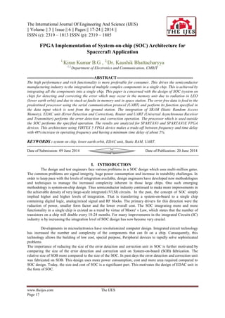
- 6. FPGA Implementation Of System-on-Chip (Soc) Architecture for Spacecraft Application www.theijes.com The IJES Page 22 Fig 5: Encoder result FIFO simulation result Fig 6: FIFO result Decoder simulation result Fig 7: Decoder result Router simulation result
- 7. FPGA Implementation Of System-on-Chip (Soc) Architecture for Spacecraft Application www.theijes.com The IJES Page 23 Fig 8: Router result EDAC unit simulation result Fig 9 : EDAC unit result The logic utilization of the design as follows Table 4.1 Logic utilization Logic Utilization Used Available Utilization Number of Slice Flip Flops 185 9,312 1% Number of 4 input LUTs 266 9,312 2% Number of occupied Slices 232 4,656 4% Number of Slices containing only related logic 232 232 100% Number of Slices containing unrelated logic 0 232 0% Total Number of 4 input LUTs 384 9,312 4% Number used as logic 240 Number used as a route-thru 118 Number used for Dual Port RAMs 24 Number used as Shift registers 2 Number of bonded-IOB’s 42 232 18% Number of BUFGMUXs 1 24 4% Average Fan-out of Non-Clock Nets 2.95
- 8. FPGA Implementation Of System-on-Chip (Soc) Architecture for Spacecraft Application www.theijes.com The IJES Page 24 V .CONCLUSION The primary goal of SOC verification is checking the integration between the various components. The role of the SOC designer is to integrate various components into a single chip rather than implementing each of the components separately. This implements complex functions in a relatively short time. The designer can concentrate on the complete system rather than checking the correctness or performance of the individual components. The complete system is designed with SRAM, EDAC unit, Router and UART and they are integrated to form a SOC design. In this integration the data input is providing to the SRAM, due to some radiations in the space and stuck at faults the data stored in the SRAM gets flipped. It is passed to the EDAC unit in order to detect and correct the errors if any bits in the SRAM are flipped. From EDAC unit it is transmit to the Router and then to processor through UART and it will process the data and provides the desired output. VI ACKNOWLEDGEMENTS I am extremely pleased to present myself this paper after getting innumerable movements and hard time with a never-ending coordination. I sincerely acknowledge offering my words of thanks to our beloved and respected Dr. Koushik Bhattacharyya, associate professor and Ms. Indumathi, professor & HOD. I sincerely acknowledge to my beloved and respected parents for their encouragement. Since thanks to Mr. Karthik, lab assistant who helped me during the paper presentation REFERENCES Journal Papers: [1] M.T. Anwar, P.K. Lala, and P. Thenappan “Decoder Design for a New Single Error Correcting/Double Error Detecting Code” International Journal of Electrical, Electronic Science and Engineering Vol.1, No.4, 2007 [2] Sanguhn Cha and Hongil Yoon, “Efficient Implementation of Single Error Correction and Double Error Detection Code with Check Bit Pre computation for Memories”, journal of semiconductor technology and science, vol.12, no.4, December 2012 [3] Ms.Neha R. Laddha and Prof. A.P.Thakare, “ Implementation of serial communication using UART with configurable baud rate”, International Journal on Recent and Innovation Trends in Computing and Communication, Vol. 1, Issue 4. Proceedings Papers: [4] Luong D. Hung, Hidetsugu Irie, Masahiro Goshima, Shuichi Sakai “Utilization of SECDED for Soft Error and Variation-Induced Defect Tolerance in Caches” [5] Rajesvari.R, Manoj.G, Angelin ponrani.M, Merin Annie Joy “IP Core Based Architecture of Telecommand System-on-Chip (SOC) for Spacecraft applications”. [6] NOVAC Ovidiu, SZTRIK Janos, VARI-KAKAS Stefan, KIM Che-Soong “Reliability Increasing Method Using a SEC-DED Hsiao Code to Cache Memories, Implemented with FPGA Circuits”, Journal of computer science and control system. [7] Christoph Borchert, Horst Schirmeier and Olaf Spinczyk “Generative Software-based Memory Error Detection and Correction for Operating System Data Structures”. Biographies and Photographs: KIRAN KUMAR B.G has received her Bachelor’s Degree B.E in Electronics and communication engineering from East Point Collage of Engineering and Technology, Bangalore of Visvesvaraya Technological University in the year 2012 and presently pursuing his M-Tech in Digital Electronics from CMR Institute of Technology, Bangalore, India.