
![Sample IJERD Paper for A4 Page Size
49
Filters that are designed using OTA-C or Gm-C are most popular in applications. Property of varying the
bias current which leads to tuning of transconductance as a design parameter makes the filter flexible in
frequency and Q-tuning , which makes OTA-C filters superior to passive filters and other active filters. In
present study the advantages OTA are dealt, which gives better controlled sharp centre frequency and the
tuning of Q of the Notch filter. [4-10]
II. CIRCUIT DESCRIPTION AND ANALASIS
Many of the basic OTA based structures use capacitors, which are attractive for integration.
Component count of these structures is often very low. An OTA integrator is a OTA-C filter, which can be
regarded as a first order low pass filter, as shown in Fig. 2. It consists of only an OTA and a capacitor. The
transfer function for this integrator can be defined as,
This is an integration function in the Laplace domain and has a low pass property
Fig 2. OTA integrator
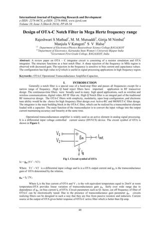
Fig. 3 gives structure of second-order OTA-C Notch filter based on the OTA integrator structure which contains
a global negative feedback. The transfer function of the filter is given below.
Fig. 3 Circuit diagram of second-order OTA-C Notch filter.
The transfer function of Notch filter is given by
The centre frequency of a Notch filter can be electronically tuned by changing gm1 and gm2 and which is given
by following expression.](data:image/gif;base64,R0lGODlhAQABAIAAAAAAAP///yH5BAEAAAAALAAAAAABAAEAAAIBRAA7)
Recomendados
Recomendados
Mais conteúdo relacionado
Mais procurados
Mais procurados (20)
Destaque
Destaque (16)
Semelhante a H1034854
Semelhante a H1034854 (20)
Mais de IJERD Editor
Mais de IJERD Editor (20)
Último
Último (20)
H1034854
- 1. International Journal of Engineering Research and Development e-ISSN: 2278-067X, p-ISSN: 2278-800X, www.ijerd.com Volume 10, Issue 3 (March 2014), PP.48-54 48 Design of OTA-C Notch Filter in Mega Hertz frequency range Rajeshwari S Mathad1 , M. M. Mutsaddi2 , Girija M Nimbal3 Manjula V Katageri4 S V Halse5 1,2 Department of Electronics/Physics Basaveshwar Science College,BAGALKOT 3,5 Department of Electronics, Karnataka State Women’s University Bijapur India 4 Government First Grade College, BAGALKOT, India Abstract: A review paper on OTA – C integrator circuit is consisting of a resistor simulation and OTA integrator. The structure functions as a best notch filter. A sharp rejection of the frequency in MHz region is observed with decreased gain. The rejection in the frequency is sensitive to bias current and capacitance values. The configuration has high value in Q which is useful in signal processing applications in high frequency region. Keywords:- OTA-C Operational Transconductance Amplifier-Capacitor, I. INTRODUCTION Generally a notch filter is a special case of a band-stop filter and passes all frequencies except for a narrow range of frequency. .High Q band reject filters have important application in RF transceiver design .The continuous-time filters were broadly used in many high speed applications, such as wireline and wireless communications, digital video, RF/IF filter etc. High Q Notch filter is an integral part of the traditional RF transceiver design. The OTA-C filters with simplicity, modularity, open loop configuration ,and electronic tune ability would be the choice for high frequency filter design over Active-RC and MOSFET-C filter design. The integrator is the main building block in the OTA-C filter, which can be realized by a transconductor element loaded with a capacitor. The main function of the transconductor is to convert the input voltage into the output current maintaining accuracy and linearity at the same time. Operational transconductances amplifier is widely used as an active element in analog signal processing. It is a differential input voltage controlled current source (DVVCS) device. The circuit symbol of OTA is shown in Figure 1. Fig 1. Circuit symbol of OTA Io = gm (V1+ - V2- ) Where V1+ - V2- is a differential input voltage and Io is a OTA output current and gm is the transconductance gain of OTA determined by the relation, gm = Ib/ 2VT Where Ib is the bias current of OTA and V T is the volt equivalent temperature equal to 26mV at room temperature.OTA provides linear variation of transconductances gain gm fairly over wide range due to dependence of gm on bias current Ib of OTA. Circuit parameters such as Q- factor, cut off frequency of filter of OTA-C can be electronically tuned. Due to the presence of transconductance gain parameter gm circuits realizing filters can be designed in such a way that they are free from passive resistors and inductors. Current source at the output of OTA gives better response of OTA-C active filter which is better than Op amp.
- 2. Sample IJERD Paper for A4 Page Size 49 Filters that are designed using OTA-C or Gm-C are most popular in applications. Property of varying the bias current which leads to tuning of transconductance as a design parameter makes the filter flexible in frequency and Q-tuning , which makes OTA-C filters superior to passive filters and other active filters. In present study the advantages OTA are dealt, which gives better controlled sharp centre frequency and the tuning of Q of the Notch filter. [4-10] II. CIRCUIT DESCRIPTION AND ANALASIS Many of the basic OTA based structures use capacitors, which are attractive for integration. Component count of these structures is often very low. An OTA integrator is a OTA-C filter, which can be regarded as a first order low pass filter, as shown in Fig. 2. It consists of only an OTA and a capacitor. The transfer function for this integrator can be defined as, This is an integration function in the Laplace domain and has a low pass property Fig 2. OTA integrator Fig. 3 gives structure of second-order OTA-C Notch filter based on the OTA integrator structure which contains a global negative feedback. The transfer function of the filter is given below. Fig. 3 Circuit diagram of second-order OTA-C Notch filter. The transfer function of Notch filter is given by The centre frequency of a Notch filter can be electronically tuned by changing gm1 and gm2 and which is given by following expression.
- 3. Sample IJERD Paper for A4 Page Size 50 The quality factor Q is given by the following expression which depends on gm1 and gm2 that is by tuning the transconductance of two OTAs Quality factor can also be given by the relation, which can be obtained by keeping gm1 = gm2 = gm .[1,2,3] III. EXPERIMENTAL SETUP The stated circuit of “Fig 4” is simulated using Proteus professional 7.5 software. Same circuit is arranged on bread board using an OTA LM13600 to verify the software results. The output of the filter is measured in respect of different values of C1 and C2, from the order of pF to nF. Readings are also analysed by varying the bias current from 100A to 2mA. with the values of sharp rejection frequencies for the stated bias currents. Fig. 4 Circuit diagram of second-order OTA-C Notch filter using Proteus professional 7.5 software IV. RESULTS AND DISCUSSION The studied circuit functions as a Notch filter of a sharp rejection frequency. The circuit is studied in two different cases. Case 1: Variation of Q, which is independent of frequency variation. Case 2: Variation of frequency Case 1: By keeping bias current constant and by varying capacitances changing C2 which gives the variation in Q The table given below gives the variation in Q, which is obtained by varying C2. and keeping C1 constant. By keeping bias current constant, and by increasing C2 from 500pF to 500nF the value of Q-factor varies from 22.36 to 707.As Q-factor increases rejection frequency decreases.
- 4. Sample IJERD Paper for A4 Page Size 51 Table 1.1 Ib1 = Ib2 = 1mA, C1= 1pF Frequency response Fig.5 Frequency response of Proteus professional simulated OTA-C notch filter circuit, with Ib1 = 1mA= Ib2= 1mA i,e gm1= gm2= 0.0192Siemens with C1 = 1pF and C2= 500nF with sharp rejection frequency of 1.28 MHz . Case 2:By keeping C1 and C2 constant and by varying bias current variation in sharp rejection frequency can be obtained. By varying the bias current of OTA1 and OTA2 and by keeping capacitance constant, variation in sharp rejection frequency is observed from 12.7MHz to 50.9MHz for bias current from 100A to 2mA.The sharp rejection frequency goes on increasing with increase in bias current for a fixed C1 and C2. However the Q factor of the notch filter goes on decreasing or increasing which depends on the combination of C1, C2, gm1 and gm2.. These observations are given in table 1.2 and table 1.3. + C2 Quality factor Q Frequency F 500pF 22.36 61.9MHz 1nF 31.62 25.6MHz 10nF 100 7.93 MHz 50nF 223 3.85MHz 100nF 316.22 2.54MHz 200nF 447.21 2.01MHz 300nF 547 1.59MHz 400nF 632 1.28MHz 500nF 707 1.28MHz
- 5. Sample IJERD Paper for A4 Page Size 52 Table 1.2 Table 1.3 C1 =1pF C2= 500pF C1 =1pF C2= 500pF and Ib1 = 1mA and Ib2 = 1mA Fig.6 Frequency response of Proteus professional simulated OTA-C notch filter circuit, with Ib1 = 1mA, Ib2= 2mA i,e gm1=0.0192Siemens , gm2= 0.038Siemens with C1 = 1pF and C2= 500nF with sharp rejection frequency of 50.9 MHz . Ib1 Frequency F Q-factor 100A 12.7MHz 7.07 500A 25.1MHz 15.81 1mA 39.4 MHz 22.6 1.5mA 50.9 MHz 27.38 Ib2 Frequency F Q-factor 100A 12.7MHz 70.71 500A 31.2MHz 31.62 1mA 40.1MHz 22.6 1.5mA 49.9MHz 18.25 2mA 50.9MHz 15.81
- 6. Sample IJERD Paper for A4 Page Size 53 Fig.7 Frequency response of Proteus professional simulated OTA-C notch filter circuit, with Ib1 = 1.5mA, Ib2= 2mA i,e gm1=,0.0288 Siemens gm2= 0.0192Siemens with C1 = 1pF and C2= 500nF with sharp rejection frequency of 50.9 MHz. From the above observations it is clear that, the Q factor is sensitive to the values of C1 and C2 , which can be varied from 1pF to 500nF, along with tune able transconductances gm1 and gm2. Sharp rejection frequency of a notch filter increases with increase in bias currents of OTA1 and OTA2 from 100uA to 2mA. V. CONCLUSIONS The studied circuit of OTA-C Notch filter exhibits a sharp rejection frequency. This frequency increases with increase in bias current in MHz frequency range. The circuit is sensitive to the values of C1 and C2 shifting the rejected frequency with a power approximated to 0dB. From over all study of observations the Q factor is sensitive to the values of C1 and C2 along with tune able transconductances gm1 and gm2. From this structure any desired signal of MHz range frequency can be effectively rejected. The increase in the value of sharp rejection frequency can be obtained by varying the bias current. As bias current increases the value of rejection frequency increases. This frequency decreases with increase in value of C1 and C2. This has applications in rejecting the noise present along with the signal in MHz range. The value of Q is greater than 1 exhibit the selectivity of the Notch filter in the range from 1 to 700 . [1,2,10] ACKNOWLEDGMENT The authors acknowledge the help rendered by VGST by giving level 1 assistance for the precurement of softwares , deviceses and instruments which have been used. The authors also acknowledge the work of transfer function presented in the thesis “Operational transconductance amplifier for Giga Hertz Applications” submitted to the, Department of Electrical and Computer Engineering, Queen’s University Kingston, Ontario, Canada (September, 2008) by You Zheng . REFERENCES [1]. You Zheng “Operational transconductance amplifier for Giga Hertz Applications” A thesis submitted to the, Department of Electrical and Computer Engineering, Queen’s University Kingston, Ontario, Canada (September, 2008) [2]. R. L. Geiger and E. Sanchez-Sinencio, “Active filter design using operational transconductance amplifiers: A tutorial,” IEEE Circuit and Device Magazine, vol.1, pp. 20-32, Mar. 1985. [3]. Anisur Rehman Nasir1 and S. Naseem Ahmad “Current-Mode Multifunction Filters Using Current- Feedback Amplifiers and Grounded Capacitors” Proceedings of the 5th National Conference; INDIACom-2011 Computing For Nation Development, March 10 – 11, 2011 Bharati Vidyapeeth’s Institute of Computer Applications and Management, James Moritz Yichuang Sun “100MHz, 6th
- 7. Sample IJERD Paper for A4 Page Size 54 Order, Leap-Frog gm-C High Q Bandpass Filter and On-Chip Tuning Scheme” 0-7803-9390- 2/06/$20.00 ©)2006 IEEE New Delhi [4]. Ms. Shivani Gupta, Ms. Suman, Ms. Sonal Aggarwal “LOW POWER CONSUMPTION CMOS DESIGN” International Journal of Research in Advent Technology (IJRAT) Vol. 1, Issue 3, October 2013, ISSN: 2321–9637 [5]. James Moritz Yichuang Sun “100MHz, 6th Order, Leap-Frog gm-C High Q Bandpass Filter and On- Chip Tuning Scheme” 0-7803-9390-2/06/$20.00 ©)2006 IEEE [6]. S Naseem Ahamed , M R Khan,operational transconductances amplifier based voltage mode Universal filter. Operational transconductances amplifier Indian Journal of pure and applied Physics Vol 43 September 2005 pp 714-719 [7]. Hai-xi. Li, Jin-yong. Zhang, Lei Wang “A Fully Integrated Continuous-Time 50-Hz Notch Filter with Center Frequency Tunability” Bulitean of advance technology research Vol. 5 No.7/ Jul. 2011 [8]. Riyas T M, Anusooya S “Design of Low Power Linear Multi-band CMOS Gm-C Filter” International Journal of Advanced Research in Electrical, Electronics and Instrumentation Engineering Vol. 3, Issue 2, February 2014 [9]. Deliyannis, Theodore L. et al "Two Integrator Loop OTA-C Filters" Continuous-Time Active Filter Design Boca Raton: CRC Press LLC,1999 [10]. Gao Zhiqiang “Design of CMOS Integrated Q-enhanced RF Filters for Multi-Band/Mode Wireless Applications” Advanced Trends in Wireless Communications ISBN 978-953-307-183-1 February, 2011 99-02, 1999.