SlideShare uma empresa Scribd logo
1 de 6
Baixar para ler offline
Umoh, Gabriel Etim, Akpan, Aniefiok Otu / International Journal of Engineering Research
                and Applications (IJERA) ISSN: 2248-9622 www.ijera.com
                    Vol. 3, Issue 1, January -February 2013, pp.1440-1445
       Application Of Digital Signal Processing In Radar Signals
                         Umoh, Gabriel Etim, Akpan, Aniefiok Otu
    Department Of Electrical/Electronics Engineering Faculty Of Engineering, Akwa Ibom State University
                         Ikot Akpaden, Mkpat Enin, Lga Akwa Ibom State, Nigeria
        Department Of Physics Faculty Of Natural Andapplied Sciences, Akwa Ibom State University
                       Ikot Akpaden, Mkpat Enin, L.G.A. Akwa Ibom State, Nigeria


Abstract
         There has been explosive growth in               pattern while at the receiver, DSP performs many
Digital Signal Processing theory and applications         complex tasks, including STAP (space time adaptive
over the years. This research explores the                processing) – the removal of clutter, and beam
applications of digital signal processing in Radar.       forming (electronic guidance of direction).
A survey on applications in digital signal                          The front end of the receiver for RADAR is
processing in Radar from a wide variety of areas          still often analog due to the high frequencies
is carried out. A review is done on basic                 involved. With fast ADC convertors-often multiple
approaching models and techniques of signal               channel, complex IF signals are digitized. However,
processing for different parameters and                   digital technology is coming closer to the antenna.
extracting information from the received signal.          We may also require fast digital interfaces to detect
The various techniques adopted at different               antenna position, or control other hardware.
stages of radar to obtain the target’s signature, is                The main task of a radar‟s signal processor
also researched.                                          is to make decisions. After a signal has been
                                                          transmitted, the receiver starts receiving return
Keywords:     Radar, Doppler, Digital Signal              signals, with those originating from near objects
Process (DSP), convolution, Clutter filters,              arriving first because time of arrival translates into
Scanning, Synthetic aperture radar (SAR),                 target range. The signal processor places a raster of
cancellers                                                range bins over the whole period of time, and now it
                                                          has to make a decision for each of the range bins as
INTRODUCTION                                              to whether it contains an object or not.
          Flexibility and versatility of digital                    This decision-making is severely hampered
techniques grew in the front-end signal processing        by noise. Atmospheric noise enters into the system
and the advent of integrated digital circuitry, high      through the antenna, and all the electronics in the
speed signal processors were developed and                radar‟s signal path produces noise too.
realized. Radar continued to grow in the recent years
by keeping the future developments in mind and            Major blocks of modern radar system
with better digital capability. Significant               The major components of modern radar are the
contributions in DSP in Radar have been in MTI            antenna, the tracking computer and the signal
processing, Automatic Detection and extraction of         generator. The tracking computer in the modern
signal, image reconstruction, etc. A case study of        radar does all the functions. By scheduling the
Radar Synthetic Vision System for Adverse                 appropriate antenna positions and transmitted
Weather Aircraft landing is discussed. In this report     signals as a function of time, keeps track of targets
an effort is made to identify the contribution of DSP     and running the display system.
in the advancement of Radars.

METHODOLOGIES
         RADAR transmits radio signals at distant
objects and analyzes the reflections. Data gathered
can include the potion and movement of the object,
also radar can identify the object through its
“signature” the distinct reflection it generates. There
are many forms of RADAR – such as continuous,
CW, Doppler, ground penetrating or synthetic
aperture; and they are used in many applications,
from air traffic control to weather prediction.
         In the modern Radar systems, digital signal
processing (DSP) is used extensively. At the
transmitter end, it generates and shapes the
transmission pulses, controls the antenna beam            Fig 1. Block Diagram of a Modern Radar system


                                                                                               1440 | P a g e
Umoh, Gabriel Etim, Akpan, Aniefiok Otu / International Journal of Engineering Research
                and Applications (IJERA) ISSN: 2248-9622 www.ijera.com
                    Vol. 3, Issue 1, January -February 2013, pp.1440-1445
Even if atmospheric attenuation can be neglected,           position in azimuth and elevation. When the
the return from a distant object is incredibly weak.        radar is tasked with surveying its sector and
Target returns often are no stronger than twice the         tracking dozens of targets, there‟s a danger of
average noise level, sometimes even buried under it.        either neglecting part of the search sector or
It is quite difficult to define a threshold for the         losing a target if the corresponding trace record
decision whether a given peak is noise or a real            isn‟t updated in time. Time management serves
target. If the threshold is too high then existing          to maintain a priority queue of all the tasks and
targets are suppressed, that is, the probability of         to produce a schedule for the beam steering
detection (PD) will drop. If the threshold is too low       device. Power management is necessary if the
then noise peaks will be reported as targets, that is,      transmitter circuitry runs the danger of
the probability of false alarms (PFA) will rise. A          overheating. If there‟s no backup hardware then
common compromise is to have some 90%                       the only way of continuing regular operation is
probability of detection and a false alarm rate of 10 -     to use less power when less power is required,
6
  .                                                         say, for track confirmation.
      It maintains a given PFA known as CFAR, for          Countering interference: Interference can be a)
Constant False Alarm Rate. Rather than keeping the          natural or b) man-made. Natural interference can
threshold at a fixed point, CFAR circuitry inspects         be heavy rain or hail storms, but also varied
one range bin after the other and compares the              propagation conditions. Man-made interference,
signal level found there with the signal levels found       if created on purpose, is also called jamming and
in its neighboring bins. If the noise level is rather       is one of the means of electronic
high in all these (e.g. because of precipitation) the       countermeasures.
CFAR circuit will raise the threshold accordingly.
Further tasks of the signal processor are:                Detection of Signals
 Combining             information:        Secondary              Detection is the process by which the
    surveillance radars like those located on airports    presence of the target is sensed in the presence of
    can ask an aircraft‟s transponder for information     competing indications which arise from background
    like height, flight number or fuel state. Pilots      echoes (clutter), atmospheric noise, or noise
    may also issue a distress signal via the              generated in the radar receiver. The noise power
    transponder. The ground radar‟s signal processor      present at the output of the radar receiver can be
    combines this data with its own measurements of       minimized by using filter, whose frequency
    range and angular direction and plots them all        response function maximizes the output peak-signal
    together on the appropriate spot on the scope.        to mean-noise (power) ratio is called matched filter.
 Forming tracks: By correlating the data sets            We shall discuss the application of digital filtering
    which were obtained in successive scan cycles,        to matched filters.
    the radar can calculate a flight vector which
    indicates an aircraft‟s speed and expected            Fast Convolution Filter Implementation
    position for the next scan period. Airport radars     (a) Dual pipeline FFTs matched Filter
    are capable of tracking hundreds of targets                     In this system, FFTs are pipelined and both
    simultaneously, and flight safety depends heavily     the forward and reverse radix-r FFTs are
    on their reliability. Military tracking radars use    implemented in hardware. Initial recording of the
    this information for gun laying or guiding            data is done using input buffer (IB) memory and it
    missiles into some calculated collision point.        takes „N/r‟ clock pulses to read N data points and „r‟
 Resolving ambiguities in range or Doppler               input rails. The amount of time „N/r‟ is called as one
    measurements: Depending on the radar‟s pulse          epoch. It requires three epochs for the first data to be
    repetition frequency (PRF), the reading for           completely filtered, and is delivered by one epoch
    range, Doppler or even both are ambiguous. The        thereafter. In the dual FFT systems arbitrary data is
    signal processor is aware of this and selects a       filtered sequentially with arbitrary reference
    different PRF when the object in question is          functions selected from reference memory.
    measured again. With a suitable set of PRFs,
    ambiguities can be eliminated and the true target     Drawback
    position can be determined.                                     In many applications the same data set be
 Ground clutter mapping: Clutter is a collective         filtered with several different filters, in this case
    term for all unwanted blips on a radar screen.        only one forward transform is performed followed
    Ground clutter originates from buildings, cars,       by several inverse transforms, it is possible to
    mountains etc, and a clutter map serves to raise      eliminate one of the pipeline FFTs. This is desirable
    the decision threshold in areas where known           since it would save a large amount of hardware.
    clutter sources are located.                          (b)       Single forward FFT matched Filter
 Time and power management: Within a                     The data is first transformed and the result stored in
    window of some 60ox40o, phased array radars           the temporary storage memory (TSM). The data is
    can instantly switch their beam position to any       then multiplied by the filter function and inverse


                                                                                                1441 | P a g e
Umoh, Gabriel Etim, Akpan, Aniefiok Otu / International Journal of Engineering Research
                and Applications (IJERA) ISSN: 2248-9622 www.ijera.com
                    Vol. 3, Issue 1, January -February 2013, pp.1440-1445
transformed. This allows multiple readouts of the
forward transformed data for the TSM and multiple
filtering of the same data set; the output of each        Input          Delay
filter will appear sequentially.                                         [IPP]

Drawback                                                                                        -
                                                                                                    Output
          The data at the output of the forward FFT
are in digit reverse order, it is then corrected by                                       +
reading the data out of the TSM in digit reversed
order. The second FFT is performed the output is         A two-pulse canceller is used if the clutter
placed into an output buffer, and to be read in a bit    component (assuming DC only) remains constant in
reversed order from the output buffer.                   a given range bin and can be eliminated by
It requires five epochs for the first data to be         subtracting the output from two successive pulses.
completely filtered, and is delivered by one epoch       The transfer function of two-pulse canceller is equal
                                                                  1
thereafter.                                              to 1  Z . And is equivalent to FIR digital filter
                                                         with magnitude response sin (  / 2 ).
(c)       Single inverse FFT matched Filter
A single inverse FFT is employed and the data is
                                                         In practice, the clutter has a power spectrum that
read from the input buffer in digit reverse order. The
                                                         covers frequencies above DC. The two-pulse
data is transformed and stored in TSM in normal
order, and then read out in bit reserve order.           canceller will attenuate low frequency components
                                                         but may not totally reject clutter. A three-pulse
Drawback
                                                         canceller with its transform function equivalent to
Complex conjugation must be performed after each
                                                                               1        2
transform and stored. The digit reversed access to       FIR filter is 0.5  z  0.5 z . This attenuates
the IB is required and the IB maybe quite large          further the components near DC.
compared to TSM and may be difficult to
implement.                                               Implementation of Clutter Filter
(d)       Reconfigurable FFT matched Filter                       The returns from the same range bin over
The FFT subsystem switches the inter-stage delay         several pulses are linearly combined to form the
lines to realize both forward and reverse transforms.    output per IPP, each delay of  can be realized
Forward transform: by routing the data through the       using shift register.
inter-stage delay memories (IDMs) in decreasing          a. The direct implementation of the optimum
order.                                                       linear processor with N points requires N
Inverse transform: by sending data through the               multiplications per output point. Since a
IDMs in the increased order of size. The total               different optimum processor is designed for
memory of each stage is the number of delay lines            each Doppler channel, the filter tap weights are
memories.                                                    different for each channel.
                                                         b. A simpler Suboptimum Processor is obtained
Comparison of 4 matched filter systems                       by cascading a three-pulse cancellor with a
          The relative performance of dual pipeline          bank of band-pass filters (implemented by a
matched filter is fastest but requires two complete          sliding FFT). N-point FFT requires N log 2 N
pipeline FFTs hence more hardware is required.
Single inverse transform matched filter has better            multiplications; only log 2 N multiplications
performance over single forward transform matched             are required per each Doppler Channel. Thus
filter and also doesn‟t require a double buffered             significant hardware simplifications are
output memory. Reconfigurable FFT matched filter              possible with this scheme provided its
is preferred and chosen most of the times, it doesn‟t         performance is adequate.
require digit reserved to the IB and also doesn‟t        E.g. moving Target Detector
require digital recording of TSM.
                                                         MTI Signal Processing
Doppler processing                                                 A major task in moving target indicator
          Doppler processing is used to filter out       (MTI) radar is to obtain a time-domain filter, with
clutter and thereby reveal fast moving targets. Such     the introduction of digital technology, these are
filters are implemented digitally, FFT or a set of       achieved using digital transversal filters, recursive
transversal filters. Cancellers and few optimized        filters and filter banks.
methods are some of the clutter rejection techniques.    Adaptive Thresholding and Automatic Detection
Cancellers                                                         Digital processing permitted the reference
          Clutter rejection filter amounts to the        level to be generated/internally from the
design of FIR digital filter with stop-bands to reject   observations themselves, thereby permitting more
the clutter frequency component. A simple filter is a    sensitive and faster thresholds. Most of the Radars
two-pulse cancelor.                                      employ automatic detection circuits to maintain,


                                                                                              1442 | P a g e
Umoh, Gabriel Etim, Akpan, Aniefiok Otu / International Journal of Engineering Research
                  and Applications (IJERA) ISSN: 2248-9622 www.ijera.com
                      Vol. 3, Issue 1, January -February 2013, pp.1440-1445
ideally, a constant false alarm rate (CFAR) by                        The adaptive threshold CFAR processors is
generating estimates of the receiver output.                 applicable to situations where the distribution of the
Automatic target detection for a search radar can be         processed data (in the no-signal case) is known
achieved by comparing the processed voltage in               generally and unknown parameters associated with
each cell to:                                                the distribution can be estimated. It is often
1. A fixed threshold level.                                  implemented as moving or sliding window through
2. Threshold levels based upon the mean amplitude            which estimates of the unknown parameters of the
   of the ambient interference.                              interference are formed.
3. A level computed on the basis of partial (a priori)
   knowledge of the interference distribution.               B. Distribution free CFAR Processors
4. A threshold level determined by distribution-free         These provide CFAR characteristics when the
   statistical hypothesis testing that assumes no            background return has an unknown distribution.
   prior knowledge of statistical distribution of the        These processors remain insensitive to variations in
   interference.                                             the distribution, and generally experiences
          In first case a detection decision is made if      additional detection loss their CFAR properties
the processed signal ro , is equal or greater than a         make their application advantageous.
                                                             1. Double Threshold Detector
present threshold. That is, if ro  T p , a detection is     2. Modified double threshold Detector
declared.                                                    3. Rank order Detector
The second and third cases represent adaptive                4. Rank-sum double quantizer Detector
threshold CFAR processors. In these processors,
estimates of the unknown parameters of the known             C.       Scanning Radar Application
distribution of the processed interference are               The optimum processor for a pulsed, non-coherent
formed. In the second case can achieve CFAR when             waveform on n pulses is a square law detector
the distribution of processed interference is                followed by a n pulse non-coherent integrator that
completely described by its mean level. The third            uses equal weighting of each detected pulse. The
case forms estimates of the unknown parameters of            integrator must not only be realizable in practical
the known (a priori) distribution.                           sense but also
The fourth case are called nonparametric CFAR                1. provide a small detection loss as possible
processors. These distribution-free process form a           2. provide a means of minimizing losses
test variable whose statistics are independent of the              associated with integration sample window
distribution of the input (non-processed)                          and scanning beam straddle of the target
interference.                                                3. In track-while scan applications, permit
                                                                   accurate measurements of the target angular
A.        Adaptive Threshold CFAR Processors                       position.


                                                                                   To adaptive Threshold
                                                                                   CFAR

                  Square law               A/D                                       Single Pulse
     IF signal                                                 ADDER
                  Detector                 Convertor                                 Delay


                                                                          Scaling
                                         Range gate                       Constant [kf]


                                              Fig.3 Square law detector


Integrators that are typically configured are sliding        Signal Processing in Synthetic Aperture Radar
window. And this requires the storage of data for n          (SAR)
inter-pulse periods. The single-loop processor               Digital processing has also permitted increased
requires storage of data for the single inter-pulse          capability for extracting target information form the
period. Of course, if data memory is somehow                 radar signal. High resolution SAR provides an
restricted and if performance is acceptable the              image of a scene. Radars are used to recognize one
feedback approach is preferred and single feedback           type of target from another, with the aid of digital
loop is shown below.                                         processing, inverse SAR (ISAR) produces an image


                                                                                                    1443 | P a g e
Umoh, Gabriel Etim, Akpan, Aniefiok Otu / International Journal of Engineering Research
                and Applications (IJERA) ISSN: 2248-9622 www.ijera.com
                    Vol. 3, Issue 1, January -February 2013, pp.1440-1445
of a target good enough to recognize from other                                             o ( vt x1 )               o ( vt x2 )
                                                                                                          2                           2

                                                                                       j                          j
classes of targets by extracting the spectrum of a
                                                          signal r (t )  e                                   e
                                                                                            cz1                         cz1
                                                                                                                                          is the
target echo signal. Interferometric SAR, which uses
two antennas spaced vertically with a common SAR          sum of two chirps.
                                                                      o [ 2 x1  x2 ) vt  x2  x1 ]
                                                                                             2    2
system, can provide height information to obtain 3D              j
image of a scene. Greater flexibility and real-time       1 e        cz1
                                                                                   will be the signal of x1 is
operation suggest digital signal processing in SAR.
                                                          considered as a reference point and is called
SAR exploits the probability density of the clutter to
                                                          dechirping. The discrimination between the two
detect man-made features by modeling the clutter by
a family of densities and picking the density that        targets are performed analyzing x1 at zero frequency
best describes the clutter on local basis.                and          target x2 analyzed   as     frequency
Fourier based methods are used for detection of
stationary and moving target detection and                2ov( x1  x2 ) / cz1 . Signal processing of the
identification in reconnaissance SAR. The                 multiplier of dechirping and FFT is carried out.
computational time of the time domain correlator          Since this approximation is done near to x1 the FFT
(TDC) is overcome in the frequency domain. Here           processing is limited to small region around the
digital spotlighting principle is used to extract the     reference point. Also it is advantageous to band-
target‟s coherent SAR signature.                          limit the dechirped azimuth signal to the frequency
Step 1                                                    range of interest and do FFT. To avoid aliasing low-
Coherent matched-filtered SAR reconstruction of           pass filter is chosen whose impulse response is a
the scene in the presence of foliage is developed by      rectangular window and the frequency response is
exploiting the angle and frequency from the target‟s             N
coherent SAR signature.                                   sin       / N sin  . The high frequency-domain
Step 2                                                    sidelobes of the rectangular window is overcome by
With the help of Fourier-based method the three           using a different window or an optimal low-pass
dimensional statistic representing the moving target      filter.
coordinates and speed is used for moving target           Thus this signal processing tends itself to a spotlight
detection.                                                mode of SAR. Small areas of central reference point
Strip Mapping SAR                                         are imaged individually and a large map is
On the incoming data, the pulse compression               constructed by piecing together several sub-maps.
matched filtering is done to obtain Range resolution      The key feature to be considered to discriminate the
and stored prior to azimuth processing. Data are          man-made structure and the foliage is the
processed one row at a time to perform the azimuth        characteristics of SAR signature of a man made
compression, since large amount of data are               metallic cylinder are different from the nature
collected large memory space is required. For each        objects such as tree with the same size of low
range resolution cell different azimuth compression       frequencies in the UHF band.
filter is required.                                       Why not shape information to distinguish
Assuming range azimuth resolutions are to be equal        targets?
and total range is mapped to  z then each memory         The resolutions of the reconstructed SAR images are
                                                          poor at UHF frequencies. The SAR magnitude
column has M samples and 2z1 / L samples
                                            2
                                                          reconstruction of both man-made targets of foliage
(niquist rate sampling) in each row.                      will appear as blobs. Thus, there is no much
The        total     storage      requirement is          discrimination about the information. By the process
              2 z 2Rmax                                 of Digital spotlighting the procedure to extract the
Memory                                                  coherent SAR signature of a target is done.
               L     L2                                   Target detection and identification
Total calculation is that required for the operation of   a.         Matched Filter Reconstruction
M azimuth pulse compression channels in parallel.         Based on the SAR principles governing the
So the total computational time using direct              variations of the gain and phase of target‟s coherent
convolution is upper- bounded by                          radar cross section with respect to the signal
2MRmax                                                   frequency and relative speed, angle, we have a
        multiplications
  L2                                                      general expression for the two-dimensional matched
By using FFT for high speed convolution together          filter that is capable of detecting a specified target in
with parallel parallelism reduces the speed               the presence of foliage.
requirement significantly.                                The measured signal S ( ku ) is passed through a
Spotlight mode SAR                                        bank of N, two-dimensional matched filters, and it is
Stretch processing is adopted, i.e., the azimuth          passed through SAR wave front reconstruction
resolution is obtained from different Doppler shifts      algorithm.
of the individual targets. Let x1 and x2 are the two
targets both at same range z1 then the received


                                                                                                                              1444 | P a g e
Umoh, Gabriel Etim, Akpan, Aniefiok Otu / International Journal of Engineering Research
                and Applications (IJERA) ISSN: 2248-9622 www.ijera.com
                    Vol. 3, Issue 1, January -February 2013, pp.1440-1445
b.        Digital      spotlight     detection      and   integration aperture, multiple images are formed. It
identification                                            is then applied to two-dimensional adaptive filters
The image filtered reconstruction requires image          used for change detection to these multiple images.
formation for all possible target types followed by a     This had an advantage with the different responses
search algorithm to detect the targets. The targets       of clutter and targets with aspect angle. Clutter
are identified by search method, extract the coherent     returns were expected to show less aspect angle
signatures, and then perform matched filtering on         dependency than targets, this property allows angle
the signature of these suspected targets. The             dependency than targets, and clutter can be removed
extraction of coherent signature from the coherent        by change detection algorithms. This technique has
reconstruction image is done and process is called        two distinct advantages over traditional change
digital spotlighting.                                     detection the multiple aperture targets are perfectly
Digital spotlighting is a computer based process that     co-registered and only one flight pass is required
isolates the target or a target region in a SAR scene.    over a given scene.
To detect and identify targets, digital spotlighting
the     reconstructed      image      f ( x, y ) is the   CONCLUSION
reconstruction domain. A stationary target‟s              In this research a brief overview of application of
signature is fairly focused and once the target           digital signal processing in Radar is presented.
signature is spotlighted, it is transformed into any      Matched filter implementation, echo cancellers and
domain of the SAR signal for identification.              automatic detection and tracking are discussed in
Detection of targets in foliage                           separate sections. In most of the modeling, Fast
Three different target detection techniques for UHF       Fourier transform is a very commonly used
SAR were discussed in this research. These                technique for analyzing and filtering digital signals.
techniques are brief out.                                 Different techniques of detection of targets in
a.        Baseline approach                               foliage are discussed for SAR. The recent advances
It consists of 3 stages with high resolution, Ka-band     in signal processing are blended with many more
SAR DATA. The first stage, a simple two-parameter         algorithms to present an up-to-date perspective and
constant false alarm rate (CFAR) detector, is a           can be implemented in Digital Signal Processor
computationally simple prescreening algorithm that        because of their flexibility and the ability to attain
rejects most natural clutter. A target detection is       high precisions.
declared if the CFAR algorithm evaluation ratio
exceeds CFAR threshold. This algorithm is followed        REFERENCES
by a clustering algorithm, which combines multiple          1.     Alan V. Oppenheim, “Application of
detections occurring in a target-sized area into a                 Digital Signal Processing”, Prentice Hall,
single detection. The combination of these two                     Inc. Eaves Reedy, “Principles of Modern
algorithms is considered to be the baseline                        Radar”.
algorithm.                                                  2.     Firooz Sadjadi, Mike Helgenson, Jeff
b.        Adaptive change detection                                Radke, Gunter Stein, “Radar Synthetic
The adaptive filters used are two-dimension                        Vision System for Adverse Weather
extensions of Widow Least mean Squares (LMS)                       Aircraft Landing”, IEEE Transactions on
filter, used as joint process estimators for noise                 Aerospace and Electronic Systems”, Jan
cancellation. Each makes use of two images, a                      1999, Vol. 35, No. 1, pp. 2-15.
primary, D [presumed to have targets] and a                 3.     Jeffrey G, Nanis, “Adaptive Filters for
reference x [without targets]. The clutter of the                  Detection of targets in Foilage”, IEEE AES
reference image is convolved with the weight                       Systems Magazin, Aug 1995, pp. 34-37.
matrix, W, to predict the corresponding clutter in the      4.     Lawrence R. Rabiner and Bernard Gold,
primary image. This primary image is subtracted                    “Theory and Applications of Digital Signal
from the primary to yield an error image, and the                  Processing”, Prentice Hall, Inc.
difference is used to adoptively tune each element of       5.     Mehradad Soumekh, “Reconnaissance with
the weigh matrix by an approximation. At each                      Ultra UHF Synthetic Aperture Radar”,
iteration, the sign of the gradient is measured. After             IEEE Signal Processing Magazine, July
consecutive sign changes, and scaling, the deviation               1995, Vol. 12, No. 4, pp. 21-39.
is found. By using two-pass change detection with           6.     P.E. Blankenship and E.M. Hofstetter,
the adaptive filters, the target-to clutter ratio is               “Digital Pulse Compression via Fast
increased.                                                         convolution”, IEEE Transactions Acoustic
c.        Multiple aperture detection                              Speech and Signal Processing, Volume
It takes off both the UHF SAR and the angular                      ASSP-23, April 1975, pp. 1898-201.
diversity of target returns. In order to achieve a high     7.     W.M. Brown and L.J. Porcello, “An
cross range resolution with a SAR operating at                     introduction to Synthetic Aperture Radar”,
FOPEAN frequencies, it is necessary to process the                 IEEE Spect., Sept. 1969, pp. 952-62.
data over a large integration angle. By splitting the


                                                                                               1445 | P a g e

Mais conteúdo relacionado

Mais procurados

Radar 2009 a 6 detection of signals in noise
Radar 2009 a 6 detection of signals in noiseRadar 2009 a 6 detection of signals in noise
Radar 2009 a 6 detection of signals in noiseForward2025
 
Design of human body scanner based on uwb
Design of human body scanner based on uwbDesign of human body scanner based on uwb
Design of human body scanner based on uwbDr.Joko Suryana
 
Radar 2009 a 18 synthetic aperture radar
Radar 2009 a 18 synthetic aperture radarRadar 2009 a 18 synthetic aperture radar
Radar 2009 a 18 synthetic aperture radarForward2025
 
Synthetic aperture radar (sar) 20150930
Synthetic aperture radar (sar) 20150930Synthetic aperture radar (sar) 20150930
Synthetic aperture radar (sar) 20150930JiyaE
 
Radar 2009 a 13 clutter rejection doppler filtering
Radar 2009 a 13 clutter rejection   doppler filteringRadar 2009 a 13 clutter rejection   doppler filtering
Radar 2009 a 13 clutter rejection doppler filteringForward2025
 
Radar Systems for NTU, 1 Nov 2014
Radar Systems for NTU, 1 Nov 2014Radar Systems for NTU, 1 Nov 2014
Radar Systems for NTU, 1 Nov 2014TBSS Group
 
Waveform LiDAR - More Than XYZ Point Clouds
Waveform LiDAR - More Than XYZ Point CloudsWaveform LiDAR - More Than XYZ Point Clouds
Waveform LiDAR - More Than XYZ Point CloudsSafe Software
 
Ultra-Wide Band: An Electronic Measuring, Communication, and Imaging Capabili...
Ultra-Wide Band: An Electronic Measuring, Communication, and Imaging Capabili...Ultra-Wide Band: An Electronic Measuring, Communication, and Imaging Capabili...
Ultra-Wide Band: An Electronic Measuring, Communication, and Imaging Capabili...Industrial Partnerships Office
 
Radar 2009 a 12 clutter rejection basics and mti
Radar 2009 a 12 clutter rejection   basics and mtiRadar 2009 a 12 clutter rejection   basics and mti
Radar 2009 a 12 clutter rejection basics and mtiForward2025
 
Radar 2009 a 14 airborne pulse doppler radar
Radar 2009 a 14 airborne pulse doppler radarRadar 2009 a 14 airborne pulse doppler radar
Radar 2009 a 14 airborne pulse doppler radarForward2025
 
14. doppler radar and mti 2014
14. doppler radar and mti 201414. doppler radar and mti 2014
14. doppler radar and mti 2014Lohith Kumar
 
Radar 2009 a 4 radar equation
Radar 2009 a  4 radar equationRadar 2009 a  4 radar equation
Radar 2009 a 4 radar equationForward2025
 
Sdr the future of radio
Sdr the future of radioSdr the future of radio
Sdr the future of radioJauwadSyed
 
Dynamic Beamforming Optimization for Anti-Jamming and Hardware Fault Recovery
Dynamic Beamforming Optimization for Anti-Jamming and Hardware Fault RecoveryDynamic Beamforming Optimization for Anti-Jamming and Hardware Fault Recovery
Dynamic Beamforming Optimization for Anti-Jamming and Hardware Fault RecoveryJonathan Becker
 
Radar 2009 a 3 review of signals, systems, and dsp
Radar 2009 a  3 review of signals, systems, and dspRadar 2009 a  3 review of signals, systems, and dsp
Radar 2009 a 3 review of signals, systems, and dspsubha5
 
Radar 2009 a 5 propagation effects
Radar 2009 a 5 propagation effectsRadar 2009 a 5 propagation effects
Radar 2009 a 5 propagation effectsForward2025
 

Mais procurados (20)

Radar 2009 a 6 detection of signals in noise
Radar 2009 a 6 detection of signals in noiseRadar 2009 a 6 detection of signals in noise
Radar 2009 a 6 detection of signals in noise
 
J010234960
J010234960J010234960
J010234960
 
Design of human body scanner based on uwb
Design of human body scanner based on uwbDesign of human body scanner based on uwb
Design of human body scanner based on uwb
 
Radar 2009 a 18 synthetic aperture radar
Radar 2009 a 18 synthetic aperture radarRadar 2009 a 18 synthetic aperture radar
Radar 2009 a 18 synthetic aperture radar
 
Synthetic aperture radar (sar) 20150930
Synthetic aperture radar (sar) 20150930Synthetic aperture radar (sar) 20150930
Synthetic aperture radar (sar) 20150930
 
Radar 2009 a 13 clutter rejection doppler filtering
Radar 2009 a 13 clutter rejection   doppler filteringRadar 2009 a 13 clutter rejection   doppler filtering
Radar 2009 a 13 clutter rejection doppler filtering
 
Radar tutorial
Radar tutorialRadar tutorial
Radar tutorial
 
Radar Systems for NTU, 1 Nov 2014
Radar Systems for NTU, 1 Nov 2014Radar Systems for NTU, 1 Nov 2014
Radar Systems for NTU, 1 Nov 2014
 
Waveform LiDAR - More Than XYZ Point Clouds
Waveform LiDAR - More Than XYZ Point CloudsWaveform LiDAR - More Than XYZ Point Clouds
Waveform LiDAR - More Than XYZ Point Clouds
 
Ultra-Wide Band: An Electronic Measuring, Communication, and Imaging Capabili...
Ultra-Wide Band: An Electronic Measuring, Communication, and Imaging Capabili...Ultra-Wide Band: An Electronic Measuring, Communication, and Imaging Capabili...
Ultra-Wide Band: An Electronic Measuring, Communication, and Imaging Capabili...
 
Radar 2009 a 12 clutter rejection basics and mti
Radar 2009 a 12 clutter rejection   basics and mtiRadar 2009 a 12 clutter rejection   basics and mti
Radar 2009 a 12 clutter rejection basics and mti
 
Introduction to Radar System & Component Tests
Introduction to Radar System & Component TestsIntroduction to Radar System & Component Tests
Introduction to Radar System & Component Tests
 
Radar 2009 a 14 airborne pulse doppler radar
Radar 2009 a 14 airborne pulse doppler radarRadar 2009 a 14 airborne pulse doppler radar
Radar 2009 a 14 airborne pulse doppler radar
 
14. doppler radar and mti 2014
14. doppler radar and mti 201414. doppler radar and mti 2014
14. doppler radar and mti 2014
 
Radar 2009 a 4 radar equation
Radar 2009 a  4 radar equationRadar 2009 a  4 radar equation
Radar 2009 a 4 radar equation
 
Sdr the future of radio
Sdr the future of radioSdr the future of radio
Sdr the future of radio
 
Report matter 2
Report matter 2Report matter 2
Report matter 2
 
Dynamic Beamforming Optimization for Anti-Jamming and Hardware Fault Recovery
Dynamic Beamforming Optimization for Anti-Jamming and Hardware Fault RecoveryDynamic Beamforming Optimization for Anti-Jamming and Hardware Fault Recovery
Dynamic Beamforming Optimization for Anti-Jamming and Hardware Fault Recovery
 
Radar 2009 a 3 review of signals, systems, and dsp
Radar 2009 a  3 review of signals, systems, and dspRadar 2009 a  3 review of signals, systems, and dsp
Radar 2009 a 3 review of signals, systems, and dsp
 
Radar 2009 a 5 propagation effects
Radar 2009 a 5 propagation effectsRadar 2009 a 5 propagation effects
Radar 2009 a 5 propagation effects
 

Destaque

Seminario - Tecnologia e Ilustração
Seminario - Tecnologia e IlustraçãoSeminario - Tecnologia e Ilustração
Seminario - Tecnologia e IlustraçãoRafael Poiate
 
Los Principales Desayunos
Los Principales DesayunosLos Principales Desayunos
Los Principales DesayunosCOVI307
 
Semana santa de inmaculada molino ortega
Semana santa de inmaculada molino ortegaSemana santa de inmaculada molino ortega
Semana santa de inmaculada molino ortegarpacmor254
 
requisitos por tipo de juicio civil y/o familiar
 requisitos por tipo de juicio civil y/o familiar requisitos por tipo de juicio civil y/o familiar
requisitos por tipo de juicio civil y/o familiarJuridicos Asociados
 
Apresentação TRIVIA COMUNICAÇÃO
Apresentação TRIVIA COMUNICAÇÃOApresentação TRIVIA COMUNICAÇÃO
Apresentação TRIVIA COMUNICAÇÃODiego Pudo
 
IMPEDIMENTOS PARA UMA COMPLETA DEPENDÊNCIA DE DEUS
IMPEDIMENTOS PARA UMA COMPLETA DEPENDÊNCIA DE DEUSIMPEDIMENTOS PARA UMA COMPLETA DEPENDÊNCIA DE DEUS
IMPEDIMENTOS PARA UMA COMPLETA DEPENDÊNCIA DE DEUSTiago Silveira
 
Recursos humanos
Recursos humanosRecursos humanos
Recursos humanosroxavil
 
Apresentação de resultados 1 t09
Apresentação de resultados 1 t09Apresentação de resultados 1 t09
Apresentação de resultados 1 t09BrasilEcodiesel
 

Destaque (20)

Ic3115271531
Ic3115271531Ic3115271531
Ic3115271531
 
If3115451551
If3115451551If3115451551
If3115451551
 
Hh3114071412
Hh3114071412Hh3114071412
Hh3114071412
 
Hi3114131415
Hi3114131415Hi3114131415
Hi3114131415
 
Ha3113551359
Ha3113551359Ha3113551359
Ha3113551359
 
Hv3114921496
Hv3114921496Hv3114921496
Hv3114921496
 
Hr3114661470
Hr3114661470Hr3114661470
Hr3114661470
 
Hj3114161424
Hj3114161424Hj3114161424
Hj3114161424
 
Ii3115651568
Ii3115651568Ii3115651568
Ii3115651568
 
Cu32604607
Cu32604607Cu32604607
Cu32604607
 
Seminario - Tecnologia e Ilustração
Seminario - Tecnologia e IlustraçãoSeminario - Tecnologia e Ilustração
Seminario - Tecnologia e Ilustração
 
fake work
fake workfake work
fake work
 
Los Principales Desayunos
Los Principales DesayunosLos Principales Desayunos
Los Principales Desayunos
 
Semana santa de inmaculada molino ortega
Semana santa de inmaculada molino ortegaSemana santa de inmaculada molino ortega
Semana santa de inmaculada molino ortega
 
requisitos por tipo de juicio civil y/o familiar
 requisitos por tipo de juicio civil y/o familiar requisitos por tipo de juicio civil y/o familiar
requisitos por tipo de juicio civil y/o familiar
 
Apresentação TRIVIA COMUNICAÇÃO
Apresentação TRIVIA COMUNICAÇÃOApresentação TRIVIA COMUNICAÇÃO
Apresentação TRIVIA COMUNICAÇÃO
 
IMPEDIMENTOS PARA UMA COMPLETA DEPENDÊNCIA DE DEUS
IMPEDIMENTOS PARA UMA COMPLETA DEPENDÊNCIA DE DEUSIMPEDIMENTOS PARA UMA COMPLETA DEPENDÊNCIA DE DEUS
IMPEDIMENTOS PARA UMA COMPLETA DEPENDÊNCIA DE DEUS
 
Edital n 5
Edital n 5Edital n 5
Edital n 5
 
Recursos humanos
Recursos humanosRecursos humanos
Recursos humanos
 
Apresentação de resultados 1 t09
Apresentação de resultados 1 t09Apresentação de resultados 1 t09
Apresentação de resultados 1 t09
 

Semelhante a DSP Applications in Radar Signals

Application Of Digital Signal Processing In Radar Signals
Application Of Digital Signal Processing In Radar SignalsApplication Of Digital Signal Processing In Radar Signals
Application Of Digital Signal Processing In Radar SignalsRichard Hogue
 
Radar target detection simulation
Radar target detection simulationRadar target detection simulation
Radar target detection simulationIJERA Editor
 
Implementation of Adaptive Digital Beamforming using Cordic
Implementation of Adaptive Digital Beamforming using CordicImplementation of Adaptive Digital Beamforming using Cordic
Implementation of Adaptive Digital Beamforming using CordicEditor IJCATR
 
Simulation of Multiple Target Detection with Frequency Modulated Continuous W...
Simulation of Multiple Target Detection with Frequency Modulated Continuous W...Simulation of Multiple Target Detection with Frequency Modulated Continuous W...
Simulation of Multiple Target Detection with Frequency Modulated Continuous W...IRJET Journal
 
International Journal of Computational Engineering Research(IJCER)
International Journal of Computational Engineering Research(IJCER)International Journal of Computational Engineering Research(IJCER)
International Journal of Computational Engineering Research(IJCER)ijceronline
 
PROJECT REPORT1 (1) new
PROJECT REPORT1 (1) newPROJECT REPORT1 (1) new
PROJECT REPORT1 (1) newAnkita Badal
 
Research paper
Research paperResearch paper
Research paperRonak Vyas
 
Clutter reduction technique based on clutter model for automatic target class...
Clutter reduction technique based on clutter model for automatic target class...Clutter reduction technique based on clutter model for automatic target class...
Clutter reduction technique based on clutter model for automatic target class...TELKOMNIKA JOURNAL
 
A SYSTEM CONCEPT FOR A 3D REAL-TIMEOFDM MIMO RADAR FOR FLYING PLATFORMS
A SYSTEM CONCEPT FOR A 3D REAL-TIMEOFDM MIMO RADAR FOR FLYING PLATFORMSA SYSTEM CONCEPT FOR A 3D REAL-TIMEOFDM MIMO RADAR FOR FLYING PLATFORMS
A SYSTEM CONCEPT FOR A 3D REAL-TIMEOFDM MIMO RADAR FOR FLYING PLATFORMSNexgen Technology
 
2014_04_msw_a4_format (2)
2014_04_msw_a4_format (2)2014_04_msw_a4_format (2)
2014_04_msw_a4_format (2)saransh kumar
 
J0412261066
J0412261066J0412261066
J0412261066IOSR-JEN
 
Nma resume jan16th
Nma resume jan16thNma resume jan16th
Nma resume jan16thNikhil Anand
 
An overview of adaptive antenna technologies for wireless communication
An overview of adaptive antenna technologies for  wireless communication An overview of adaptive antenna technologies for  wireless communication
An overview of adaptive antenna technologies for wireless communication marwaeng
 
SHIPS MATCHING BASED ON AN ADAPTIVE ACOUSTIC SPECTRUM SIGNATURE DETECTION ALG...
SHIPS MATCHING BASED ON AN ADAPTIVE ACOUSTIC SPECTRUM SIGNATURE DETECTION ALG...SHIPS MATCHING BASED ON AN ADAPTIVE ACOUSTIC SPECTRUM SIGNATURE DETECTION ALG...
SHIPS MATCHING BASED ON AN ADAPTIVE ACOUSTIC SPECTRUM SIGNATURE DETECTION ALG...sipij
 

Semelhante a DSP Applications in Radar Signals (20)

Application Of Digital Signal Processing In Radar Signals
Application Of Digital Signal Processing In Radar SignalsApplication Of Digital Signal Processing In Radar Signals
Application Of Digital Signal Processing In Radar Signals
 
Radar target detection simulation
Radar target detection simulationRadar target detection simulation
Radar target detection simulation
 
Bb4201362367
Bb4201362367Bb4201362367
Bb4201362367
 
Implementation of Adaptive Digital Beamforming using Cordic
Implementation of Adaptive Digital Beamforming using CordicImplementation of Adaptive Digital Beamforming using Cordic
Implementation of Adaptive Digital Beamforming using Cordic
 
Simulation of Multiple Target Detection with Frequency Modulated Continuous W...
Simulation of Multiple Target Detection with Frequency Modulated Continuous W...Simulation of Multiple Target Detection with Frequency Modulated Continuous W...
Simulation of Multiple Target Detection with Frequency Modulated Continuous W...
 
International Journal of Computational Engineering Research(IJCER)
International Journal of Computational Engineering Research(IJCER)International Journal of Computational Engineering Research(IJCER)
International Journal of Computational Engineering Research(IJCER)
 
PROJECT REPORT1 (1) new
PROJECT REPORT1 (1) newPROJECT REPORT1 (1) new
PROJECT REPORT1 (1) new
 
R adar
R adarR adar
R adar
 
Hl3413921395
Hl3413921395Hl3413921395
Hl3413921395
 
Research paper
Research paperResearch paper
Research paper
 
Clutter reduction technique based on clutter model for automatic target class...
Clutter reduction technique based on clutter model for automatic target class...Clutter reduction technique based on clutter model for automatic target class...
Clutter reduction technique based on clutter model for automatic target class...
 
F41014349
F41014349F41014349
F41014349
 
A SYSTEM CONCEPT FOR A 3D REAL-TIMEOFDM MIMO RADAR FOR FLYING PLATFORMS
A SYSTEM CONCEPT FOR A 3D REAL-TIMEOFDM MIMO RADAR FOR FLYING PLATFORMSA SYSTEM CONCEPT FOR A 3D REAL-TIMEOFDM MIMO RADAR FOR FLYING PLATFORMS
A SYSTEM CONCEPT FOR A 3D REAL-TIMEOFDM MIMO RADAR FOR FLYING PLATFORMS
 
Nv2422562263
Nv2422562263Nv2422562263
Nv2422562263
 
2014_04_msw_a4_format (2)
2014_04_msw_a4_format (2)2014_04_msw_a4_format (2)
2014_04_msw_a4_format (2)
 
J0412261066
J0412261066J0412261066
J0412261066
 
Nma resume jan16th
Nma resume jan16thNma resume jan16th
Nma resume jan16th
 
Radar
RadarRadar
Radar
 
An overview of adaptive antenna technologies for wireless communication
An overview of adaptive antenna technologies for  wireless communication An overview of adaptive antenna technologies for  wireless communication
An overview of adaptive antenna technologies for wireless communication
 
SHIPS MATCHING BASED ON AN ADAPTIVE ACOUSTIC SPECTRUM SIGNATURE DETECTION ALG...
SHIPS MATCHING BASED ON AN ADAPTIVE ACOUSTIC SPECTRUM SIGNATURE DETECTION ALG...SHIPS MATCHING BASED ON AN ADAPTIVE ACOUSTIC SPECTRUM SIGNATURE DETECTION ALG...
SHIPS MATCHING BASED ON AN ADAPTIVE ACOUSTIC SPECTRUM SIGNATURE DETECTION ALG...
 

DSP Applications in Radar Signals

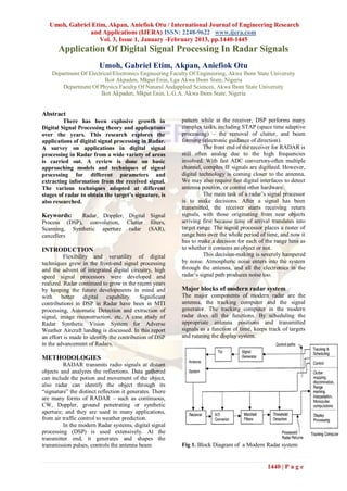
  • 1. Umoh, Gabriel Etim, Akpan, Aniefiok Otu / International Journal of Engineering Research and Applications (IJERA) ISSN: 2248-9622 www.ijera.com Vol. 3, Issue 1, January -February 2013, pp.1440-1445 Application Of Digital Signal Processing In Radar Signals Umoh, Gabriel Etim, Akpan, Aniefiok Otu Department Of Electrical/Electronics Engineering Faculty Of Engineering, Akwa Ibom State University Ikot Akpaden, Mkpat Enin, Lga Akwa Ibom State, Nigeria Department Of Physics Faculty Of Natural Andapplied Sciences, Akwa Ibom State University Ikot Akpaden, Mkpat Enin, L.G.A. Akwa Ibom State, Nigeria Abstract There has been explosive growth in pattern while at the receiver, DSP performs many Digital Signal Processing theory and applications complex tasks, including STAP (space time adaptive over the years. This research explores the processing) – the removal of clutter, and beam applications of digital signal processing in Radar. forming (electronic guidance of direction). A survey on applications in digital signal The front end of the receiver for RADAR is processing in Radar from a wide variety of areas still often analog due to the high frequencies is carried out. A review is done on basic involved. With fast ADC convertors-often multiple approaching models and techniques of signal channel, complex IF signals are digitized. However, processing for different parameters and digital technology is coming closer to the antenna. extracting information from the received signal. We may also require fast digital interfaces to detect The various techniques adopted at different antenna position, or control other hardware. stages of radar to obtain the target’s signature, is The main task of a radar‟s signal processor also researched. is to make decisions. After a signal has been transmitted, the receiver starts receiving return Keywords: Radar, Doppler, Digital Signal signals, with those originating from near objects Process (DSP), convolution, Clutter filters, arriving first because time of arrival translates into Scanning, Synthetic aperture radar (SAR), target range. The signal processor places a raster of cancellers range bins over the whole period of time, and now it has to make a decision for each of the range bins as INTRODUCTION to whether it contains an object or not. Flexibility and versatility of digital This decision-making is severely hampered techniques grew in the front-end signal processing by noise. Atmospheric noise enters into the system and the advent of integrated digital circuitry, high through the antenna, and all the electronics in the speed signal processors were developed and radar‟s signal path produces noise too. realized. Radar continued to grow in the recent years by keeping the future developments in mind and Major blocks of modern radar system with better digital capability. Significant The major components of modern radar are the contributions in DSP in Radar have been in MTI antenna, the tracking computer and the signal processing, Automatic Detection and extraction of generator. The tracking computer in the modern signal, image reconstruction, etc. A case study of radar does all the functions. By scheduling the Radar Synthetic Vision System for Adverse appropriate antenna positions and transmitted Weather Aircraft landing is discussed. In this report signals as a function of time, keeps track of targets an effort is made to identify the contribution of DSP and running the display system. in the advancement of Radars. METHODOLOGIES RADAR transmits radio signals at distant objects and analyzes the reflections. Data gathered can include the potion and movement of the object, also radar can identify the object through its “signature” the distinct reflection it generates. There are many forms of RADAR – such as continuous, CW, Doppler, ground penetrating or synthetic aperture; and they are used in many applications, from air traffic control to weather prediction. In the modern Radar systems, digital signal processing (DSP) is used extensively. At the transmitter end, it generates and shapes the transmission pulses, controls the antenna beam Fig 1. Block Diagram of a Modern Radar system 1440 | P a g e
  • 2. Umoh, Gabriel Etim, Akpan, Aniefiok Otu / International Journal of Engineering Research and Applications (IJERA) ISSN: 2248-9622 www.ijera.com Vol. 3, Issue 1, January -February 2013, pp.1440-1445 Even if atmospheric attenuation can be neglected, position in azimuth and elevation. When the the return from a distant object is incredibly weak. radar is tasked with surveying its sector and Target returns often are no stronger than twice the tracking dozens of targets, there‟s a danger of average noise level, sometimes even buried under it. either neglecting part of the search sector or It is quite difficult to define a threshold for the losing a target if the corresponding trace record decision whether a given peak is noise or a real isn‟t updated in time. Time management serves target. If the threshold is too high then existing to maintain a priority queue of all the tasks and targets are suppressed, that is, the probability of to produce a schedule for the beam steering detection (PD) will drop. If the threshold is too low device. Power management is necessary if the then noise peaks will be reported as targets, that is, transmitter circuitry runs the danger of the probability of false alarms (PFA) will rise. A overheating. If there‟s no backup hardware then common compromise is to have some 90% the only way of continuing regular operation is probability of detection and a false alarm rate of 10 - to use less power when less power is required, 6 . say, for track confirmation. It maintains a given PFA known as CFAR, for  Countering interference: Interference can be a) Constant False Alarm Rate. Rather than keeping the natural or b) man-made. Natural interference can threshold at a fixed point, CFAR circuitry inspects be heavy rain or hail storms, but also varied one range bin after the other and compares the propagation conditions. Man-made interference, signal level found there with the signal levels found if created on purpose, is also called jamming and in its neighboring bins. If the noise level is rather is one of the means of electronic high in all these (e.g. because of precipitation) the countermeasures. CFAR circuit will raise the threshold accordingly. Further tasks of the signal processor are: Detection of Signals  Combining information: Secondary Detection is the process by which the surveillance radars like those located on airports presence of the target is sensed in the presence of can ask an aircraft‟s transponder for information competing indications which arise from background like height, flight number or fuel state. Pilots echoes (clutter), atmospheric noise, or noise may also issue a distress signal via the generated in the radar receiver. The noise power transponder. The ground radar‟s signal processor present at the output of the radar receiver can be combines this data with its own measurements of minimized by using filter, whose frequency range and angular direction and plots them all response function maximizes the output peak-signal together on the appropriate spot on the scope. to mean-noise (power) ratio is called matched filter.  Forming tracks: By correlating the data sets We shall discuss the application of digital filtering which were obtained in successive scan cycles, to matched filters. the radar can calculate a flight vector which indicates an aircraft‟s speed and expected Fast Convolution Filter Implementation position for the next scan period. Airport radars (a) Dual pipeline FFTs matched Filter are capable of tracking hundreds of targets In this system, FFTs are pipelined and both simultaneously, and flight safety depends heavily the forward and reverse radix-r FFTs are on their reliability. Military tracking radars use implemented in hardware. Initial recording of the this information for gun laying or guiding data is done using input buffer (IB) memory and it missiles into some calculated collision point. takes „N/r‟ clock pulses to read N data points and „r‟  Resolving ambiguities in range or Doppler input rails. The amount of time „N/r‟ is called as one measurements: Depending on the radar‟s pulse epoch. It requires three epochs for the first data to be repetition frequency (PRF), the reading for completely filtered, and is delivered by one epoch range, Doppler or even both are ambiguous. The thereafter. In the dual FFT systems arbitrary data is signal processor is aware of this and selects a filtered sequentially with arbitrary reference different PRF when the object in question is functions selected from reference memory. measured again. With a suitable set of PRFs, ambiguities can be eliminated and the true target Drawback position can be determined. In many applications the same data set be  Ground clutter mapping: Clutter is a collective filtered with several different filters, in this case term for all unwanted blips on a radar screen. only one forward transform is performed followed Ground clutter originates from buildings, cars, by several inverse transforms, it is possible to mountains etc, and a clutter map serves to raise eliminate one of the pipeline FFTs. This is desirable the decision threshold in areas where known since it would save a large amount of hardware. clutter sources are located. (b) Single forward FFT matched Filter  Time and power management: Within a The data is first transformed and the result stored in window of some 60ox40o, phased array radars the temporary storage memory (TSM). The data is can instantly switch their beam position to any then multiplied by the filter function and inverse 1441 | P a g e
  • 3. Umoh, Gabriel Etim, Akpan, Aniefiok Otu / International Journal of Engineering Research and Applications (IJERA) ISSN: 2248-9622 www.ijera.com Vol. 3, Issue 1, January -February 2013, pp.1440-1445 transformed. This allows multiple readouts of the forward transformed data for the TSM and multiple filtering of the same data set; the output of each Input Delay filter will appear sequentially. [IPP] Drawback - Output The data at the output of the forward FFT are in digit reverse order, it is then corrected by + reading the data out of the TSM in digit reversed order. The second FFT is performed the output is A two-pulse canceller is used if the clutter placed into an output buffer, and to be read in a bit component (assuming DC only) remains constant in reversed order from the output buffer. a given range bin and can be eliminated by It requires five epochs for the first data to be subtracting the output from two successive pulses. completely filtered, and is delivered by one epoch The transfer function of two-pulse canceller is equal 1 thereafter. to 1  Z . And is equivalent to FIR digital filter with magnitude response sin (  / 2 ). (c) Single inverse FFT matched Filter A single inverse FFT is employed and the data is In practice, the clutter has a power spectrum that read from the input buffer in digit reverse order. The covers frequencies above DC. The two-pulse data is transformed and stored in TSM in normal order, and then read out in bit reserve order. canceller will attenuate low frequency components but may not totally reject clutter. A three-pulse Drawback canceller with its transform function equivalent to Complex conjugation must be performed after each 1 2 transform and stored. The digit reversed access to FIR filter is 0.5  z  0.5 z . This attenuates the IB is required and the IB maybe quite large further the components near DC. compared to TSM and may be difficult to implement. Implementation of Clutter Filter (d) Reconfigurable FFT matched Filter The returns from the same range bin over The FFT subsystem switches the inter-stage delay several pulses are linearly combined to form the lines to realize both forward and reverse transforms. output per IPP, each delay of  can be realized Forward transform: by routing the data through the using shift register. inter-stage delay memories (IDMs) in decreasing a. The direct implementation of the optimum order. linear processor with N points requires N Inverse transform: by sending data through the multiplications per output point. Since a IDMs in the increased order of size. The total different optimum processor is designed for memory of each stage is the number of delay lines each Doppler channel, the filter tap weights are memories. different for each channel. b. A simpler Suboptimum Processor is obtained Comparison of 4 matched filter systems by cascading a three-pulse cancellor with a The relative performance of dual pipeline bank of band-pass filters (implemented by a matched filter is fastest but requires two complete sliding FFT). N-point FFT requires N log 2 N pipeline FFTs hence more hardware is required. Single inverse transform matched filter has better multiplications; only log 2 N multiplications performance over single forward transform matched are required per each Doppler Channel. Thus filter and also doesn‟t require a double buffered significant hardware simplifications are output memory. Reconfigurable FFT matched filter possible with this scheme provided its is preferred and chosen most of the times, it doesn‟t performance is adequate. require digit reserved to the IB and also doesn‟t E.g. moving Target Detector require digital recording of TSM. MTI Signal Processing Doppler processing A major task in moving target indicator Doppler processing is used to filter out (MTI) radar is to obtain a time-domain filter, with clutter and thereby reveal fast moving targets. Such the introduction of digital technology, these are filters are implemented digitally, FFT or a set of achieved using digital transversal filters, recursive transversal filters. Cancellers and few optimized filters and filter banks. methods are some of the clutter rejection techniques. Adaptive Thresholding and Automatic Detection Cancellers Digital processing permitted the reference Clutter rejection filter amounts to the level to be generated/internally from the design of FIR digital filter with stop-bands to reject observations themselves, thereby permitting more the clutter frequency component. A simple filter is a sensitive and faster thresholds. Most of the Radars two-pulse cancelor. employ automatic detection circuits to maintain, 1442 | P a g e
  • 4. Umoh, Gabriel Etim, Akpan, Aniefiok Otu / International Journal of Engineering Research and Applications (IJERA) ISSN: 2248-9622 www.ijera.com Vol. 3, Issue 1, January -February 2013, pp.1440-1445 ideally, a constant false alarm rate (CFAR) by The adaptive threshold CFAR processors is generating estimates of the receiver output. applicable to situations where the distribution of the Automatic target detection for a search radar can be processed data (in the no-signal case) is known achieved by comparing the processed voltage in generally and unknown parameters associated with each cell to: the distribution can be estimated. It is often 1. A fixed threshold level. implemented as moving or sliding window through 2. Threshold levels based upon the mean amplitude which estimates of the unknown parameters of the of the ambient interference. interference are formed. 3. A level computed on the basis of partial (a priori) knowledge of the interference distribution. B. Distribution free CFAR Processors 4. A threshold level determined by distribution-free These provide CFAR characteristics when the statistical hypothesis testing that assumes no background return has an unknown distribution. prior knowledge of statistical distribution of the These processors remain insensitive to variations in interference. the distribution, and generally experiences In first case a detection decision is made if additional detection loss their CFAR properties the processed signal ro , is equal or greater than a make their application advantageous. 1. Double Threshold Detector present threshold. That is, if ro  T p , a detection is 2. Modified double threshold Detector declared. 3. Rank order Detector The second and third cases represent adaptive 4. Rank-sum double quantizer Detector threshold CFAR processors. In these processors, estimates of the unknown parameters of the known C. Scanning Radar Application distribution of the processed interference are The optimum processor for a pulsed, non-coherent formed. In the second case can achieve CFAR when waveform on n pulses is a square law detector the distribution of processed interference is followed by a n pulse non-coherent integrator that completely described by its mean level. The third uses equal weighting of each detected pulse. The case forms estimates of the unknown parameters of integrator must not only be realizable in practical the known (a priori) distribution. sense but also The fourth case are called nonparametric CFAR 1. provide a small detection loss as possible processors. These distribution-free process form a 2. provide a means of minimizing losses test variable whose statistics are independent of the associated with integration sample window distribution of the input (non-processed) and scanning beam straddle of the target interference. 3. In track-while scan applications, permit accurate measurements of the target angular A. Adaptive Threshold CFAR Processors position. To adaptive Threshold CFAR Square law A/D Single Pulse IF signal ADDER Detector Convertor Delay Scaling Range gate Constant [kf] Fig.3 Square law detector Integrators that are typically configured are sliding Signal Processing in Synthetic Aperture Radar window. And this requires the storage of data for n (SAR) inter-pulse periods. The single-loop processor Digital processing has also permitted increased requires storage of data for the single inter-pulse capability for extracting target information form the period. Of course, if data memory is somehow radar signal. High resolution SAR provides an restricted and if performance is acceptable the image of a scene. Radars are used to recognize one feedback approach is preferred and single feedback type of target from another, with the aid of digital loop is shown below. processing, inverse SAR (ISAR) produces an image 1443 | P a g e
  • 5. Umoh, Gabriel Etim, Akpan, Aniefiok Otu / International Journal of Engineering Research and Applications (IJERA) ISSN: 2248-9622 www.ijera.com Vol. 3, Issue 1, January -February 2013, pp.1440-1445 of a target good enough to recognize from other o ( vt x1 ) o ( vt x2 ) 2 2 j j classes of targets by extracting the spectrum of a signal r (t )  e e cz1 cz1 is the target echo signal. Interferometric SAR, which uses two antennas spaced vertically with a common SAR sum of two chirps. o [ 2 x1  x2 ) vt  x2  x1 ] 2 2 system, can provide height information to obtain 3D j image of a scene. Greater flexibility and real-time 1 e cz1 will be the signal of x1 is operation suggest digital signal processing in SAR. considered as a reference point and is called SAR exploits the probability density of the clutter to dechirping. The discrimination between the two detect man-made features by modeling the clutter by a family of densities and picking the density that targets are performed analyzing x1 at zero frequency best describes the clutter on local basis. and target x2 analyzed as frequency Fourier based methods are used for detection of stationary and moving target detection and 2ov( x1  x2 ) / cz1 . Signal processing of the identification in reconnaissance SAR. The multiplier of dechirping and FFT is carried out. computational time of the time domain correlator Since this approximation is done near to x1 the FFT (TDC) is overcome in the frequency domain. Here processing is limited to small region around the digital spotlighting principle is used to extract the reference point. Also it is advantageous to band- target‟s coherent SAR signature. limit the dechirped azimuth signal to the frequency Step 1 range of interest and do FFT. To avoid aliasing low- Coherent matched-filtered SAR reconstruction of pass filter is chosen whose impulse response is a the scene in the presence of foliage is developed by rectangular window and the frequency response is exploiting the angle and frequency from the target‟s N coherent SAR signature. sin / N sin  . The high frequency-domain Step 2 sidelobes of the rectangular window is overcome by With the help of Fourier-based method the three using a different window or an optimal low-pass dimensional statistic representing the moving target filter. coordinates and speed is used for moving target Thus this signal processing tends itself to a spotlight detection. mode of SAR. Small areas of central reference point Strip Mapping SAR are imaged individually and a large map is On the incoming data, the pulse compression constructed by piecing together several sub-maps. matched filtering is done to obtain Range resolution The key feature to be considered to discriminate the and stored prior to azimuth processing. Data are man-made structure and the foliage is the processed one row at a time to perform the azimuth characteristics of SAR signature of a man made compression, since large amount of data are metallic cylinder are different from the nature collected large memory space is required. For each objects such as tree with the same size of low range resolution cell different azimuth compression frequencies in the UHF band. filter is required. Why not shape information to distinguish Assuming range azimuth resolutions are to be equal targets? and total range is mapped to  z then each memory The resolutions of the reconstructed SAR images are poor at UHF frequencies. The SAR magnitude column has M samples and 2z1 / L samples 2 reconstruction of both man-made targets of foliage (niquist rate sampling) in each row. will appear as blobs. Thus, there is no much The total storage requirement is discrimination about the information. By the process 2 z 2Rmax of Digital spotlighting the procedure to extract the Memory   coherent SAR signature of a target is done. L L2 Target detection and identification Total calculation is that required for the operation of a. Matched Filter Reconstruction M azimuth pulse compression channels in parallel. Based on the SAR principles governing the So the total computational time using direct variations of the gain and phase of target‟s coherent convolution is upper- bounded by radar cross section with respect to the signal 2MRmax frequency and relative speed, angle, we have a multiplications L2 general expression for the two-dimensional matched By using FFT for high speed convolution together filter that is capable of detecting a specified target in with parallel parallelism reduces the speed the presence of foliage. requirement significantly. The measured signal S ( ku ) is passed through a Spotlight mode SAR bank of N, two-dimensional matched filters, and it is Stretch processing is adopted, i.e., the azimuth passed through SAR wave front reconstruction resolution is obtained from different Doppler shifts algorithm. of the individual targets. Let x1 and x2 are the two targets both at same range z1 then the received 1444 | P a g e
  • 6. Umoh, Gabriel Etim, Akpan, Aniefiok Otu / International Journal of Engineering Research and Applications (IJERA) ISSN: 2248-9622 www.ijera.com Vol. 3, Issue 1, January -February 2013, pp.1440-1445 b. Digital spotlight detection and integration aperture, multiple images are formed. It identification is then applied to two-dimensional adaptive filters The image filtered reconstruction requires image used for change detection to these multiple images. formation for all possible target types followed by a This had an advantage with the different responses search algorithm to detect the targets. The targets of clutter and targets with aspect angle. Clutter are identified by search method, extract the coherent returns were expected to show less aspect angle signatures, and then perform matched filtering on dependency than targets, this property allows angle the signature of these suspected targets. The dependency than targets, and clutter can be removed extraction of coherent signature from the coherent by change detection algorithms. This technique has reconstruction image is done and process is called two distinct advantages over traditional change digital spotlighting. detection the multiple aperture targets are perfectly Digital spotlighting is a computer based process that co-registered and only one flight pass is required isolates the target or a target region in a SAR scene. over a given scene. To detect and identify targets, digital spotlighting the reconstructed image f ( x, y ) is the CONCLUSION reconstruction domain. A stationary target‟s In this research a brief overview of application of signature is fairly focused and once the target digital signal processing in Radar is presented. signature is spotlighted, it is transformed into any Matched filter implementation, echo cancellers and domain of the SAR signal for identification. automatic detection and tracking are discussed in Detection of targets in foliage separate sections. In most of the modeling, Fast Three different target detection techniques for UHF Fourier transform is a very commonly used SAR were discussed in this research. These technique for analyzing and filtering digital signals. techniques are brief out. Different techniques of detection of targets in a. Baseline approach foliage are discussed for SAR. The recent advances It consists of 3 stages with high resolution, Ka-band in signal processing are blended with many more SAR DATA. The first stage, a simple two-parameter algorithms to present an up-to-date perspective and constant false alarm rate (CFAR) detector, is a can be implemented in Digital Signal Processor computationally simple prescreening algorithm that because of their flexibility and the ability to attain rejects most natural clutter. A target detection is high precisions. declared if the CFAR algorithm evaluation ratio exceeds CFAR threshold. This algorithm is followed REFERENCES by a clustering algorithm, which combines multiple 1. Alan V. Oppenheim, “Application of detections occurring in a target-sized area into a Digital Signal Processing”, Prentice Hall, single detection. The combination of these two Inc. Eaves Reedy, “Principles of Modern algorithms is considered to be the baseline Radar”. algorithm. 2. Firooz Sadjadi, Mike Helgenson, Jeff b. Adaptive change detection Radke, Gunter Stein, “Radar Synthetic The adaptive filters used are two-dimension Vision System for Adverse Weather extensions of Widow Least mean Squares (LMS) Aircraft Landing”, IEEE Transactions on filter, used as joint process estimators for noise Aerospace and Electronic Systems”, Jan cancellation. Each makes use of two images, a 1999, Vol. 35, No. 1, pp. 2-15. primary, D [presumed to have targets] and a 3. Jeffrey G, Nanis, “Adaptive Filters for reference x [without targets]. The clutter of the Detection of targets in Foilage”, IEEE AES reference image is convolved with the weight Systems Magazin, Aug 1995, pp. 34-37. matrix, W, to predict the corresponding clutter in the 4. Lawrence R. Rabiner and Bernard Gold, primary image. This primary image is subtracted “Theory and Applications of Digital Signal from the primary to yield an error image, and the Processing”, Prentice Hall, Inc. difference is used to adoptively tune each element of 5. Mehradad Soumekh, “Reconnaissance with the weigh matrix by an approximation. At each Ultra UHF Synthetic Aperture Radar”, iteration, the sign of the gradient is measured. After IEEE Signal Processing Magazine, July consecutive sign changes, and scaling, the deviation 1995, Vol. 12, No. 4, pp. 21-39. is found. By using two-pass change detection with 6. P.E. Blankenship and E.M. Hofstetter, the adaptive filters, the target-to clutter ratio is “Digital Pulse Compression via Fast increased. convolution”, IEEE Transactions Acoustic c. Multiple aperture detection Speech and Signal Processing, Volume It takes off both the UHF SAR and the angular ASSP-23, April 1975, pp. 1898-201. diversity of target returns. In order to achieve a high 7. W.M. Brown and L.J. Porcello, “An cross range resolution with a SAR operating at introduction to Synthetic Aperture Radar”, FOPEAN frequencies, it is necessary to process the IEEE Spect., Sept. 1969, pp. 952-62. data over a large integration angle. By splitting the 1445 | P a g e