SlideShare uma empresa Scribd logo
1 de 50
Choppers
Fixed DC Supply Variable DC Output
?
A. K. Gautam
By: Aniruddha Kr. Gautam
• A chopper is a static device which is used to
obtain a variable dc voltage from a constant dc
voltage source.
• Also known as dc‐to‐dc converter.
• It offers greater efficiency, faster response, lower
maintenance, smaller size and smooth control.
• Widely used in trolley cars, battery operated
vehicles, traction motor control, control of large
number of dc motors, etc…
• Also used in regenerative braking of dc motors to
return energy back to supply and also as dc
voltage regulators.
A. K. Gautam
METHODS OF CONTROL:
The output dc voltage can be verified by the following methods.
• Constant Frequency Control or Pulse width modulation control
• Variable Frequency Control
PULSE WIDTH MODULATION
In Pulse width modulation the pulse width ton of the output waveform
is varied keeping chopping frequency ’f’ and hence chopping period ‘T’
constant. Therefore output voltage is varied by varying the ON time, ton .
Figure shows the output voltage waveform for different ON times.
VARIABLE FREQUENCY CONTROL
In this method of control, chopping frequency f is varied keeping
either ton or toff constant. This method is also known as frequency
modulation.
In frequency modulation to obtain full output voltage, range of
frequency has to be varied over a wide range. This method produces
harmonics in the output and for large toff load current may be
discontinuous.
A. K. Gautam
A. K. Gautam
V0
V
V
V0
t
t
tON
tON tOFF
tOFF
T
A. K. Gautam
v0
V
V
v0
t
t
tON
tON
T
T
tOFF
tOFF
Basic DC to DC converters
• Buck converter (Step-down converter)
• Boost converter (Step-up converter)
• Buck-Boost converter (Step-down/step-up converter)
and
• Cuk converter
A. K. Gautam
Buck converter (Step-down converter)
A. K. Gautam
A. K. Gautam
• Diode is reversed biased.
Switch conducts inductor
current
• This results in positive
inductor voltage, i.e.:
VL=Vd-VO
• It causes linear increase in
the inductor current.
A. K. Gautam
Circuit operation when switch is turned on (closed)
Operation when switch turned off (opened)
• Because of inductive energy
storage, iL continues to flow.
• Diode is forward biased.
• Current now flows through
the diode and,
A. K. Gautam
Analysis for switch closed
• The inductor voltage
• Since the derivative if iL is a
positive constant. Therefore
iL must increase linearly.
A. K. Gautam
A. K. Gautam
Analysis for switch opened
Steady-state operation
• Steady state operation
requires that iL
• Steady state operation
requires that iL at the end of
switching cycle is the same
at the beginning of the next
cycle. That is change of iL
over one period is zero. i.e.
A. K. Gautam
Steady State Time Domain Analysis of Type-A Chopper
A. K. Gautam
Output
voltage
Output
current
v0
V
i0
Imax
Imin
t
t
tON
T
tOFF
Continuous
current
Output
current
t
Discontinuous
current
i0
Expressions For Load Current iO For Continuous Current
Operation When Chopper is ON (0 t tON)
A. K. Gautam
V
i0
V0
R
L
E
+
-
A. K. Gautam
A. K. Gautam
A. K. Gautam
Steady State Ripple
A. K. Gautam
)26.2.........(....................
1
11
1
1
1
1
1
1
1
1
)(
minmax
a
aonaon
aa
aonaon
a
aon
a
aon
a
aon
TT
TTTTT
S
TTTT
TTTT
TT
TT
S
TT
TT
TT
TT
S
e
ee
R
V
ee
ee
e
e
R
V
e
e
e
e
R
V
II
The ripple current given by the equation is seen to be independent of load
current emf E With Ton= αT and T-Ton = (1-α)T can be written as
a
a
T
a
T
T
TT
T
S
e
ee
R
V
II
1
11
1
minmax
Limit of Continuous Conduction
• In a chopper if Ton is reduced , Toff increases for a constant chopping period
T.
• As Ton gets low and Toff goes high so current I may fall to zero.
• As in step down chopper current cannot go reverse so for limit current can
go to only zero from Imin (Eqn. 2.20)
• We can get value of α is obtain by equating the above equation.
A. K. Gautam
)27.2.......(....................11ln
1
1
0
1
1
'
min
a
a
a
on
a
a
on
T
T
aon
ST
T
T
T
T
T
T
T
S
em
T
T
T
T
m
V
E
e
e
R
E
e
e
R
V
I
• So for Given Value of E, VS, T and Ta; if duty cycle is α’ then
current goes at just continuous point.
• If actual duty cycle is less than α’ , load current will be
discontinuous.
A. K. Gautam
CCM and DCM of Buck Converter
A. K. Gautam
Step Up (Boost)Chopper
A. K. Gautam
• A boost converter (step-up converter) is a DC-to-
DC power converter with an output voltage greater
than its input voltage.
• It is a class of switched-mode power supply (SMPS)
containing at least two semiconductor switches
(a diode and a transistor) and at least one energy
storage element, a capacitor, inductor, or the two in
combination.
• Boost converter is also used as the voltage increase
mechanism in the circuit known as the 'Joule thief'.
• For a step-up chopper we can obtain an average
output voltage V0 greater than input voltage.
A. K. Gautam
• Step-up chopper is used to obtain a load voltage higher
than the input voltage V.
• The values of L and C are chosen depending upon the
requirement of output voltage and current.
• When the chopper is ON, the inductor L is connected
across the supply.
• The inductor current ‘I’ rises and the inductor stores
energy during the ON time of the chopper, tON.
• When the chopper is off, the inductor current I is forced
to flow through the diode D and load for a period, tOFF.
• The current tends to decrease resulting in reversing the
polarity of induced EMF in L.
• Therefore voltage across load is given by:
A. K. Gautam
• A large capacitor ‘C’ connected across the load, will provide a
continuous output voltage .
• Diode D prevents any current flow from capacitor to the
source.
A. K. Gautam
. .,O O
dI
V V L i e V V
dt
Operating Principle
• The key principle that drives the boost converter is the
tendency of an inductor to resist changes in current.
Mode 1 (On State):
When the switch is closed, current flows through the inductor in
clockwise direction and the inductor stores the energy. Polarity
of the left side of the inductor is positive.
A. K. Gautam
Mode 2 (Off State)
When the switch is opened, current will be reduced as the
impedance is higher. Therefore, change or reduction in current
will be opposed by the inductor. Thus the polarity will be
reversed (means left side of inductor will be negative now). As
a result two sources will be in series causing a higher voltage
to charge the capacitor through the diode D.
Here the switch is open and the only path offered to inductor
current is through the flyback diode D, the capacitor C and the
load R.
A. K. Gautam
Mode of conduction
Continuous Conduction mode:
• When a boost converter operates in continuous mode, the current through
the inductor (IL) never falls to zero.
• During the On-state, the switch S is closed, which makes the input voltage
(Vi) appear across the inductor.
• Change in current (IL) flowing through the inductor during a time period (t)
by the formula:
• At the end of the On-state, the increase of IL is therefore:
A. K. Gautam
L
V
t
I iL
i
DT
iL V
L
DT
dtV
L
I on
0
1
• D is the duty cycle. It represents the fraction of the
commutation period T during which the switch is On.
• D ranges between 0 (S is never on) and 1 (S is always on).
• During the Off-state, the switch S is open, so the inductor
current flows through the load. If we consider zero voltage
drop in the diode, and a capacitor large enough for its voltage
to remain constant, the evolution of IL is:
• Therefore, the variation of IL during the Off-period is:
A. K. Gautam
dt
dI
LVV L
oi
L
TDVV
L
dtVV
I oi
T
DT
oi
Loff
1)()(
• considering that the converter operates in steady-state
conditions, so the amount of energy stored in each of its
components has to be the same at the beginning and at the end
of a commutation cycle. In particular, the energy stored in the
inductor is given by:
• So, the inductor current has to be the same at the start and end
of the commutation cycle. This means the overall change in
the current (the sum of the changes) is zero:
A. K. Gautam
2
2
1
LLIE
0
1
0
L
TDVV
L
DTV
II
II
oii
Ll
Ll
offon
offon
• Expression shows that the output voltage is
always higher than the input voltage (as the
duty cycle goes from 0 to 1), and that it
increases with D,
A. K. Gautam
o
i
i
o
V
V
D
DV
V
1
1
1
A. K. Gautam
Discontinuous Conduction mode:
• If the ripple amplitude of the current is too high, the
inductor may be completely discharged before the
end of a whole commutation cycle.
• Occurs under light loads.
• Here the current through the inductor falls to zero
during part of the period.
• As the inductor current at the beginning of the cycle
is zero, its maximum value:
A. K. Gautam
)( DTtat
L
DTV
I i
LMax
• During the off-period, IL falls to zero after :
• The load current Io is equal to the average diode current (ID).
Also the diode current is equal to the inductor current during
the off-state. Therefore the output current can be written as:
A. K. Gautam
io
i
i
L
VV
DV
So
L
TVV
I Max
,
0
)( 0
o
i
i
o
io
i
io
ii
o
L
Do
LI
TDV
V
V
So
VVL
TDV
VV
DV
L
DTV
ISo
I
II Maz
2
1,
22
,
2
2
22
A. K. Gautam
(CCM) and (DCM) of boost
A. K. Gautam
Types of Choppers
• Type A Chopper or First–Quadrant Chopper
• Type B Chopper or Second-Quadrant Chopper
• Type-C chopper or Two-quadrant type-A
Chopper
• Type-D Chopper or Two-Quadrant Type–B
Chopper
• Type-E chopper or the Fourth-Quadrant
Chopper
A. K. Gautam
Type A Chopper or First–Quadrant Chopper
A. K. Gautam
• When chopper is ON, supply voltage V is connected across the
load.
• When chopper is OFF, vO = 0 and the load current continues to
flow in the same direction through the FWD.
• The average values of output voltage and current are always
positive.
• Class A Chopper is a step-down chopper in which power
always flows form source to load.
• It is used to control the speed of dc motor.
• The output current equations obtained in step down chopper
• with R-L load can be used to study the performance of Class A
Chopper
A. K. Gautam
Type B Chopper or Second-Quadrant Chopper
A. K. Gautam
• When chopper is ON, E drives a current through L and
R in a direction opposite to that shown in figure.
• During the ON period of the chopper, the inductance L
stores energy.
• When Chopper is OFF, diode D conducts, and part of
the energy stored in inductor L is returned to the supply.
• Average output voltage is positive and average output
current is negative.
• In this chopper, power flows from load to source.
• Class B Chopper is used for regenerative braking of dc
motor.
• Class B Chopper is a step-up chopper.
A. K. Gautam
Type-C chopper or Two-quadrant type-A Chopper
A. K. Gautam
• Class C Chopper is a combination of Class A and Class B
Choppers.
• For first quadrant operation, CH1 is ON or D2 conducts.
• For second quadrant operation, CH2 is ON or D1 conducts.
• When CH1 is ON, the load current is positive.
• The output voltage is equal to ‘V’ & the load receives power
from the source.
• When CH1 is turned OFF, energy stored in inductance L forces
current to flow through the diode D2 and the output voltage is
zero.
• Current continues to flow in positive direction.
• When CH2 is triggered, the voltage E forces current to flow in
opposite direction through L and CH2
• The output voltage is zero.
A. K. Gautam
• On turning OFF CH2, the energy stored in the inductance
drives current through diode D1 and the supply Output voltage
is V, the input current becomes negative and power flows from
load to source.
• Average output voltage is positive
• Average output current can take both positive and negative
values.
• Choppers CH1 & CH2 should not be turned ON
simultaneously as it would result in short circuiting the supply.
• Class C Chopper can be used both for dc motor control and
regenerative braking of dc motor.
• Class C Chopper can be used as a step-up or step-down
chopper.
A. K. Gautam
Type-D Chopper or Two-Quadrant Type –B Chopper
A. K. Gautam
• Class D is a two quadrant chopper.
• When both CH1 and CH2 are triggered simultaneously,
the output voltage vO = V and output current flows
through the load.
• When CH1 and CH2 are turned OFF, the load current
continues to flow in the same direction through load, D1
and D2, due to the energy stored in the inductor L.
• Output voltage vO = - V
• Average load voltage is positive if chopper ON time is
more than the OFF time
• Average output voltage becomes negative if tON < tOFF .
• Hence the direction of load current is always positive but
load voltage can be positive or negative.
A. K. Gautam
Type-E chopper or the Fourth-Quadrant Chopper
A. K. Gautam
• Class E is a four quadrant chopper
• When CH1 and CH4 are triggered, output current
iO flows in positive direction through CH1 and
CH4 , and with output voltage vO = V.
• This gives the first quadrant operation.
• When both CH1 and CH4 are OFF, the energy
stored in the inductor L drives iO through D2 and
D3 in the same direction, but output voltage vO = -
V.
• Therefore the chopper operates in the fourth
quadrant.
A. K. Gautam
• When CH2 and CH3 are triggered, the load current iO
flows in opposite direction & output voltage vO = -V.
• Since both iO and vO are negative, the chopper
operates in third quadrant.
• When both CH2 and CH3 are OFF, the load current iO
continues to flow in the same direction D1 andD4 and
the output voltage vO = V.
• Therefore the chopper operates in second quadrant as
vO is positive but iO is negative.
A. K. Gautam

Mais conteúdo relacionado

Mais procurados

Buck-Boost Converter
Buck-Boost ConverterBuck-Boost Converter
Buck-Boost ConverterSagar Patil
 
Controlled Rectifier
Controlled RectifierControlled Rectifier
Controlled RectifierFaraz Ahmed
 
speed control of three phase induction motor
speed control of three phase induction motorspeed control of three phase induction motor
speed control of three phase induction motorAshvani Shukla
 
Buck boost converter
Buck boost converterBuck boost converter
Buck boost converterSaumya Pandey
 
POWER SWITCHING DEVICES
POWER SWITCHING DEVICESPOWER SWITCHING DEVICES
POWER SWITCHING DEVICESSadanandam4u
 
Dc Choppers
Dc ChoppersDc Choppers
Dc Choppersstooty s
 
Lecture 2: Power Diodes
Lecture 2: Power DiodesLecture 2: Power Diodes
Lecture 2: Power Diodesaadesharya
 
dc to dc-converter
dc to dc-converterdc to dc-converter
dc to dc-converterStudent
 
Single phase full bridge inverter
Single phase full bridge inverterSingle phase full bridge inverter
Single phase full bridge inverterNisarg Amin
 
Protection of power transformer
Protection of power transformerProtection of power transformer
Protection of power transformerRitesh Verma
 
PERMANENT MAGNET BRUSHLESS DC MOTOR
PERMANENT MAGNET BRUSHLESS DC MOTORPERMANENT MAGNET BRUSHLESS DC MOTOR
PERMANENT MAGNET BRUSHLESS DC MOTORArchana Balachandran
 
Cyclo converters
Cyclo convertersCyclo converters
Cyclo convertersJaya Shree
 

Mais procurados (20)

Buck-Boost Converter
Buck-Boost ConverterBuck-Boost Converter
Buck-Boost Converter
 
Thyristor
Thyristor Thyristor
Thyristor
 
Controlled Rectifier
Controlled RectifierControlled Rectifier
Controlled Rectifier
 
speed control of three phase induction motor
speed control of three phase induction motorspeed control of three phase induction motor
speed control of three phase induction motor
 
Buck boost converter
Buck boost converterBuck boost converter
Buck boost converter
 
Ac voltage controller
Ac voltage controllerAc voltage controller
Ac voltage controller
 
POWER SWITCHING DEVICES
POWER SWITCHING DEVICESPOWER SWITCHING DEVICES
POWER SWITCHING DEVICES
 
Dc Choppers
Dc ChoppersDc Choppers
Dc Choppers
 
Lecture 2: Power Diodes
Lecture 2: Power DiodesLecture 2: Power Diodes
Lecture 2: Power Diodes
 
dc to dc-converter
dc to dc-converterdc to dc-converter
dc to dc-converter
 
Single phase full bridge inverter
Single phase full bridge inverterSingle phase full bridge inverter
Single phase full bridge inverter
 
Scr firing circuits
Scr firing circuitsScr firing circuits
Scr firing circuits
 
Boost converter
Boost converterBoost converter
Boost converter
 
Protection of power transformer
Protection of power transformerProtection of power transformer
Protection of power transformer
 
Unit 2 choppers
Unit 2 choppersUnit 2 choppers
Unit 2 choppers
 
Choppers
ChoppersChoppers
Choppers
 
Chopper operation
Chopper  operationChopper  operation
Chopper operation
 
PERMANENT MAGNET BRUSHLESS DC MOTOR
PERMANENT MAGNET BRUSHLESS DC MOTORPERMANENT MAGNET BRUSHLESS DC MOTOR
PERMANENT MAGNET BRUSHLESS DC MOTOR
 
Boost converter
Boost converterBoost converter
Boost converter
 
Cyclo converters
Cyclo convertersCyclo converters
Cyclo converters
 

Semelhante a Choppers

lecture 10 - electrical machines - dc to dc converters 1.pptx
lecture 10 - electrical machines - dc to dc converters 1.pptxlecture 10 - electrical machines - dc to dc converters 1.pptx
lecture 10 - electrical machines - dc to dc converters 1.pptxJohnkamanda3
 
Inverters (DC-AC)
Inverters (DC-AC)Inverters (DC-AC)
Inverters (DC-AC)Taimur Ijaz
 
Power electronic dc to dc converter
Power electronic dc to dc converterPower electronic dc to dc converter
Power electronic dc to dc convertermoazalhosne
 
DC-DC power processing
DC-DC power processingDC-DC power processing
DC-DC power processingTaimur Ijaz
 
Online classes pe dc-dc converter
Online classes pe dc-dc converterOnline classes pe dc-dc converter
Online classes pe dc-dc converterAmit Kulkarni
 
Choppers and cycloconverters
Choppers and cycloconvertersChoppers and cycloconverters
Choppers and cycloconvertersSHIMI S L
 
L5-DC to DC CONVERTER.ppt
L5-DC to DC CONVERTER.pptL5-DC to DC CONVERTER.ppt
L5-DC to DC CONVERTER.pptantexnebyu
 
PED drivers t5656979089897877ghvvnvgcxxn
PED drivers t5656979089897877ghvvnvgcxxnPED drivers t5656979089897877ghvvnvgcxxn
PED drivers t5656979089897877ghvvnvgcxxnnightbot15
 
Simulation of Boost Converter Using MATLAB SIMULINK.
Simulation of  Boost Converter Using MATLAB SIMULINK.Simulation of  Boost Converter Using MATLAB SIMULINK.
Simulation of Boost Converter Using MATLAB SIMULINK.Raviraj solanki
 
Thyristor technology
Thyristor technologyThyristor technology
Thyristor technologySHIMI S L
 

Semelhante a Choppers (20)

Choppers ppt
Choppers pptChoppers ppt
Choppers ppt
 
Switching regulators
Switching regulatorsSwitching regulators
Switching regulators
 
UNIT - 6.pdf
UNIT - 6.pdfUNIT - 6.pdf
UNIT - 6.pdf
 
Chopper
ChopperChopper
Chopper
 
lecture 10 - electrical machines - dc to dc converters 1.pptx
lecture 10 - electrical machines - dc to dc converters 1.pptxlecture 10 - electrical machines - dc to dc converters 1.pptx
lecture 10 - electrical machines - dc to dc converters 1.pptx
 
Inverters (DC-AC)
Inverters (DC-AC)Inverters (DC-AC)
Inverters (DC-AC)
 
Power electronic dc to dc converter
Power electronic dc to dc converterPower electronic dc to dc converter
Power electronic dc to dc converter
 
DC-DC power processing
DC-DC power processingDC-DC power processing
DC-DC power processing
 
Lecture slides_Ch_6 power electronics daniel hart.pdf
Lecture slides_Ch_6 power electronics daniel hart.pdfLecture slides_Ch_6 power electronics daniel hart.pdf
Lecture slides_Ch_6 power electronics daniel hart.pdf
 
Online classes pe dc-dc converter
Online classes pe dc-dc converterOnline classes pe dc-dc converter
Online classes pe dc-dc converter
 
CS.PROJECT.pptx
CS.PROJECT.pptxCS.PROJECT.pptx
CS.PROJECT.pptx
 
Choppers and cycloconverters
Choppers and cycloconvertersChoppers and cycloconverters
Choppers and cycloconverters
 
L5-DC to DC CONVERTER.ppt
L5-DC to DC CONVERTER.pptL5-DC to DC CONVERTER.ppt
L5-DC to DC CONVERTER.ppt
 
PE_Converters.ppt
PE_Converters.pptPE_Converters.ppt
PE_Converters.ppt
 
Choppers
ChoppersChoppers
Choppers
 
Multivibrators.pptx
Multivibrators.pptxMultivibrators.pptx
Multivibrators.pptx
 
PED drivers t5656979089897877ghvvnvgcxxn
PED drivers t5656979089897877ghvvnvgcxxnPED drivers t5656979089897877ghvvnvgcxxn
PED drivers t5656979089897877ghvvnvgcxxn
 
Simulation of Boost Converter Using MATLAB SIMULINK.
Simulation of  Boost Converter Using MATLAB SIMULINK.Simulation of  Boost Converter Using MATLAB SIMULINK.
Simulation of Boost Converter Using MATLAB SIMULINK.
 
DC DC Converter.pptx
DC DC Converter.pptxDC DC Converter.pptx
DC DC Converter.pptx
 
Thyristor technology
Thyristor technologyThyristor technology
Thyristor technology
 

Último

Visit to a blind student's school🧑‍🦯🧑‍🦯(community medicine)
Visit to a blind student's school🧑‍🦯🧑‍🦯(community medicine)Visit to a blind student's school🧑‍🦯🧑‍🦯(community medicine)
Visit to a blind student's school🧑‍🦯🧑‍🦯(community medicine)lakshayb543
 
THEORIES OF ORGANIZATION-PUBLIC ADMINISTRATION
THEORIES OF ORGANIZATION-PUBLIC ADMINISTRATIONTHEORIES OF ORGANIZATION-PUBLIC ADMINISTRATION
THEORIES OF ORGANIZATION-PUBLIC ADMINISTRATIONHumphrey A Beña
 
Science 7 Quarter 4 Module 2: Natural Resources.pptx
Science 7 Quarter 4 Module 2: Natural Resources.pptxScience 7 Quarter 4 Module 2: Natural Resources.pptx
Science 7 Quarter 4 Module 2: Natural Resources.pptxMaryGraceBautista27
 
USPS® Forced Meter Migration - How to Know if Your Postage Meter Will Soon be...
USPS® Forced Meter Migration - How to Know if Your Postage Meter Will Soon be...USPS® Forced Meter Migration - How to Know if Your Postage Meter Will Soon be...
USPS® Forced Meter Migration - How to Know if Your Postage Meter Will Soon be...Postal Advocate Inc.
 
Incoming and Outgoing Shipments in 3 STEPS Using Odoo 17
Incoming and Outgoing Shipments in 3 STEPS Using Odoo 17Incoming and Outgoing Shipments in 3 STEPS Using Odoo 17
Incoming and Outgoing Shipments in 3 STEPS Using Odoo 17Celine George
 
Full Stack Web Development Course for Beginners
Full Stack Web Development Course  for BeginnersFull Stack Web Development Course  for Beginners
Full Stack Web Development Course for BeginnersSabitha Banu
 
How to do quick user assign in kanban in Odoo 17 ERP
How to do quick user assign in kanban in Odoo 17 ERPHow to do quick user assign in kanban in Odoo 17 ERP
How to do quick user assign in kanban in Odoo 17 ERPCeline George
 
Proudly South Africa powerpoint Thorisha.pptx
Proudly South Africa powerpoint Thorisha.pptxProudly South Africa powerpoint Thorisha.pptx
Proudly South Africa powerpoint Thorisha.pptxthorishapillay1
 
ACC 2024 Chronicles. Cardiology. Exam.pdf
ACC 2024 Chronicles. Cardiology. Exam.pdfACC 2024 Chronicles. Cardiology. Exam.pdf
ACC 2024 Chronicles. Cardiology. Exam.pdfSpandanaRallapalli
 
4.18.24 Movement Legacies, Reflection, and Review.pptx
4.18.24 Movement Legacies, Reflection, and Review.pptx4.18.24 Movement Legacies, Reflection, and Review.pptx
4.18.24 Movement Legacies, Reflection, and Review.pptxmary850239
 
INTRODUCTION TO CATHOLIC CHRISTOLOGY.pptx
INTRODUCTION TO CATHOLIC CHRISTOLOGY.pptxINTRODUCTION TO CATHOLIC CHRISTOLOGY.pptx
INTRODUCTION TO CATHOLIC CHRISTOLOGY.pptxHumphrey A Beña
 
Barangay Council for the Protection of Children (BCPC) Orientation.pptx
Barangay Council for the Protection of Children (BCPC) Orientation.pptxBarangay Council for the Protection of Children (BCPC) Orientation.pptx
Barangay Council for the Protection of Children (BCPC) Orientation.pptxCarlos105
 
Computed Fields and api Depends in the Odoo 17
Computed Fields and api Depends in the Odoo 17Computed Fields and api Depends in the Odoo 17
Computed Fields and api Depends in the Odoo 17Celine George
 
Field Attribute Index Feature in Odoo 17
Field Attribute Index Feature in Odoo 17Field Attribute Index Feature in Odoo 17
Field Attribute Index Feature in Odoo 17Celine George
 
How to Add Barcode on PDF Report in Odoo 17
How to Add Barcode on PDF Report in Odoo 17How to Add Barcode on PDF Report in Odoo 17
How to Add Barcode on PDF Report in Odoo 17Celine George
 

Último (20)

TataKelola dan KamSiber Kecerdasan Buatan v022.pdf
TataKelola dan KamSiber Kecerdasan Buatan v022.pdfTataKelola dan KamSiber Kecerdasan Buatan v022.pdf
TataKelola dan KamSiber Kecerdasan Buatan v022.pdf
 
Visit to a blind student's school🧑‍🦯🧑‍🦯(community medicine)
Visit to a blind student's school🧑‍🦯🧑‍🦯(community medicine)Visit to a blind student's school🧑‍🦯🧑‍🦯(community medicine)
Visit to a blind student's school🧑‍🦯🧑‍🦯(community medicine)
 
THEORIES OF ORGANIZATION-PUBLIC ADMINISTRATION
THEORIES OF ORGANIZATION-PUBLIC ADMINISTRATIONTHEORIES OF ORGANIZATION-PUBLIC ADMINISTRATION
THEORIES OF ORGANIZATION-PUBLIC ADMINISTRATION
 
Science 7 Quarter 4 Module 2: Natural Resources.pptx
Science 7 Quarter 4 Module 2: Natural Resources.pptxScience 7 Quarter 4 Module 2: Natural Resources.pptx
Science 7 Quarter 4 Module 2: Natural Resources.pptx
 
USPS® Forced Meter Migration - How to Know if Your Postage Meter Will Soon be...
USPS® Forced Meter Migration - How to Know if Your Postage Meter Will Soon be...USPS® Forced Meter Migration - How to Know if Your Postage Meter Will Soon be...
USPS® Forced Meter Migration - How to Know if Your Postage Meter Will Soon be...
 
Incoming and Outgoing Shipments in 3 STEPS Using Odoo 17
Incoming and Outgoing Shipments in 3 STEPS Using Odoo 17Incoming and Outgoing Shipments in 3 STEPS Using Odoo 17
Incoming and Outgoing Shipments in 3 STEPS Using Odoo 17
 
Raw materials used in Herbal Cosmetics.pptx
Raw materials used in Herbal Cosmetics.pptxRaw materials used in Herbal Cosmetics.pptx
Raw materials used in Herbal Cosmetics.pptx
 
Full Stack Web Development Course for Beginners
Full Stack Web Development Course  for BeginnersFull Stack Web Development Course  for Beginners
Full Stack Web Development Course for Beginners
 
How to do quick user assign in kanban in Odoo 17 ERP
How to do quick user assign in kanban in Odoo 17 ERPHow to do quick user assign in kanban in Odoo 17 ERP
How to do quick user assign in kanban in Odoo 17 ERP
 
Proudly South Africa powerpoint Thorisha.pptx
Proudly South Africa powerpoint Thorisha.pptxProudly South Africa powerpoint Thorisha.pptx
Proudly South Africa powerpoint Thorisha.pptx
 
ACC 2024 Chronicles. Cardiology. Exam.pdf
ACC 2024 Chronicles. Cardiology. Exam.pdfACC 2024 Chronicles. Cardiology. Exam.pdf
ACC 2024 Chronicles. Cardiology. Exam.pdf
 
4.18.24 Movement Legacies, Reflection, and Review.pptx
4.18.24 Movement Legacies, Reflection, and Review.pptx4.18.24 Movement Legacies, Reflection, and Review.pptx
4.18.24 Movement Legacies, Reflection, and Review.pptx
 
OS-operating systems- ch04 (Threads) ...
OS-operating systems- ch04 (Threads) ...OS-operating systems- ch04 (Threads) ...
OS-operating systems- ch04 (Threads) ...
 
INTRODUCTION TO CATHOLIC CHRISTOLOGY.pptx
INTRODUCTION TO CATHOLIC CHRISTOLOGY.pptxINTRODUCTION TO CATHOLIC CHRISTOLOGY.pptx
INTRODUCTION TO CATHOLIC CHRISTOLOGY.pptx
 
Barangay Council for the Protection of Children (BCPC) Orientation.pptx
Barangay Council for the Protection of Children (BCPC) Orientation.pptxBarangay Council for the Protection of Children (BCPC) Orientation.pptx
Barangay Council for the Protection of Children (BCPC) Orientation.pptx
 
Computed Fields and api Depends in the Odoo 17
Computed Fields and api Depends in the Odoo 17Computed Fields and api Depends in the Odoo 17
Computed Fields and api Depends in the Odoo 17
 
Field Attribute Index Feature in Odoo 17
Field Attribute Index Feature in Odoo 17Field Attribute Index Feature in Odoo 17
Field Attribute Index Feature in Odoo 17
 
YOUVE GOT EMAIL_FINALS_EL_DORADO_2024.pptx
YOUVE GOT EMAIL_FINALS_EL_DORADO_2024.pptxYOUVE GOT EMAIL_FINALS_EL_DORADO_2024.pptx
YOUVE GOT EMAIL_FINALS_EL_DORADO_2024.pptx
 
YOUVE_GOT_EMAIL_PRELIMS_EL_DORADO_2024.pptx
YOUVE_GOT_EMAIL_PRELIMS_EL_DORADO_2024.pptxYOUVE_GOT_EMAIL_PRELIMS_EL_DORADO_2024.pptx
YOUVE_GOT_EMAIL_PRELIMS_EL_DORADO_2024.pptx
 
How to Add Barcode on PDF Report in Odoo 17
How to Add Barcode on PDF Report in Odoo 17How to Add Barcode on PDF Report in Odoo 17
How to Add Barcode on PDF Report in Odoo 17
 

Choppers

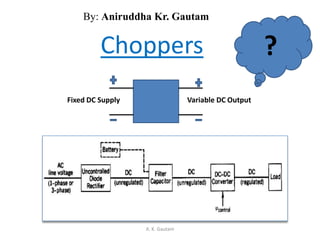
  • 1. Choppers Fixed DC Supply Variable DC Output ? A. K. Gautam By: Aniruddha Kr. Gautam
  • 2. • A chopper is a static device which is used to obtain a variable dc voltage from a constant dc voltage source. • Also known as dc‐to‐dc converter. • It offers greater efficiency, faster response, lower maintenance, smaller size and smooth control. • Widely used in trolley cars, battery operated vehicles, traction motor control, control of large number of dc motors, etc… • Also used in regenerative braking of dc motors to return energy back to supply and also as dc voltage regulators. A. K. Gautam
  • 3. METHODS OF CONTROL: The output dc voltage can be verified by the following methods. • Constant Frequency Control or Pulse width modulation control • Variable Frequency Control PULSE WIDTH MODULATION In Pulse width modulation the pulse width ton of the output waveform is varied keeping chopping frequency ’f’ and hence chopping period ‘T’ constant. Therefore output voltage is varied by varying the ON time, ton . Figure shows the output voltage waveform for different ON times. VARIABLE FREQUENCY CONTROL In this method of control, chopping frequency f is varied keeping either ton or toff constant. This method is also known as frequency modulation. In frequency modulation to obtain full output voltage, range of frequency has to be varied over a wide range. This method produces harmonics in the output and for large toff load current may be discontinuous. A. K. Gautam
  • 6. Basic DC to DC converters • Buck converter (Step-down converter) • Boost converter (Step-up converter) • Buck-Boost converter (Step-down/step-up converter) and • Cuk converter A. K. Gautam
  • 7. Buck converter (Step-down converter) A. K. Gautam
  • 9. • Diode is reversed biased. Switch conducts inductor current • This results in positive inductor voltage, i.e.: VL=Vd-VO • It causes linear increase in the inductor current. A. K. Gautam Circuit operation when switch is turned on (closed)
  • 10. Operation when switch turned off (opened) • Because of inductive energy storage, iL continues to flow. • Diode is forward biased. • Current now flows through the diode and, A. K. Gautam
  • 11. Analysis for switch closed • The inductor voltage • Since the derivative if iL is a positive constant. Therefore iL must increase linearly. A. K. Gautam
  • 12. A. K. Gautam Analysis for switch opened
  • 13. Steady-state operation • Steady state operation requires that iL • Steady state operation requires that iL at the end of switching cycle is the same at the beginning of the next cycle. That is change of iL over one period is zero. i.e. A. K. Gautam
  • 14. Steady State Time Domain Analysis of Type-A Chopper A. K. Gautam Output voltage Output current v0 V i0 Imax Imin t t tON T tOFF Continuous current Output current t Discontinuous current i0
  • 15. Expressions For Load Current iO For Continuous Current Operation When Chopper is ON (0 t tON) A. K. Gautam V i0 V0 R L E + -
  • 19. Steady State Ripple A. K. Gautam )26.2.........(.................... 1 11 1 1 1 1 1 1 1 1 )( minmax a aonaon aa aonaon a aon a aon a aon TT TTTTT S TTTT TTTT TT TT S TT TT TT TT S e ee R V ee ee e e R V e e e e R V II The ripple current given by the equation is seen to be independent of load current emf E With Ton= αT and T-Ton = (1-α)T can be written as a a T a T T TT T S e ee R V II 1 11 1 minmax
  • 20. Limit of Continuous Conduction • In a chopper if Ton is reduced , Toff increases for a constant chopping period T. • As Ton gets low and Toff goes high so current I may fall to zero. • As in step down chopper current cannot go reverse so for limit current can go to only zero from Imin (Eqn. 2.20) • We can get value of α is obtain by equating the above equation. A. K. Gautam )27.2.......(....................11ln 1 1 0 1 1 ' min a a a on a a on T T aon ST T T T T T T T S em T T T T m V E e e R E e e R V I
  • 21. • So for Given Value of E, VS, T and Ta; if duty cycle is α’ then current goes at just continuous point. • If actual duty cycle is less than α’ , load current will be discontinuous. A. K. Gautam
  • 22. CCM and DCM of Buck Converter A. K. Gautam
  • 24. • A boost converter (step-up converter) is a DC-to- DC power converter with an output voltage greater than its input voltage. • It is a class of switched-mode power supply (SMPS) containing at least two semiconductor switches (a diode and a transistor) and at least one energy storage element, a capacitor, inductor, or the two in combination. • Boost converter is also used as the voltage increase mechanism in the circuit known as the 'Joule thief'. • For a step-up chopper we can obtain an average output voltage V0 greater than input voltage. A. K. Gautam
  • 25. • Step-up chopper is used to obtain a load voltage higher than the input voltage V. • The values of L and C are chosen depending upon the requirement of output voltage and current. • When the chopper is ON, the inductor L is connected across the supply. • The inductor current ‘I’ rises and the inductor stores energy during the ON time of the chopper, tON. • When the chopper is off, the inductor current I is forced to flow through the diode D and load for a period, tOFF. • The current tends to decrease resulting in reversing the polarity of induced EMF in L. • Therefore voltage across load is given by: A. K. Gautam
  • 26. • A large capacitor ‘C’ connected across the load, will provide a continuous output voltage . • Diode D prevents any current flow from capacitor to the source. A. K. Gautam . .,O O dI V V L i e V V dt
  • 27. Operating Principle • The key principle that drives the boost converter is the tendency of an inductor to resist changes in current. Mode 1 (On State): When the switch is closed, current flows through the inductor in clockwise direction and the inductor stores the energy. Polarity of the left side of the inductor is positive. A. K. Gautam
  • 28. Mode 2 (Off State) When the switch is opened, current will be reduced as the impedance is higher. Therefore, change or reduction in current will be opposed by the inductor. Thus the polarity will be reversed (means left side of inductor will be negative now). As a result two sources will be in series causing a higher voltage to charge the capacitor through the diode D. Here the switch is open and the only path offered to inductor current is through the flyback diode D, the capacitor C and the load R. A. K. Gautam
  • 29. Mode of conduction Continuous Conduction mode: • When a boost converter operates in continuous mode, the current through the inductor (IL) never falls to zero. • During the On-state, the switch S is closed, which makes the input voltage (Vi) appear across the inductor. • Change in current (IL) flowing through the inductor during a time period (t) by the formula: • At the end of the On-state, the increase of IL is therefore: A. K. Gautam L V t I iL i DT iL V L DT dtV L I on 0 1
  • 30. • D is the duty cycle. It represents the fraction of the commutation period T during which the switch is On. • D ranges between 0 (S is never on) and 1 (S is always on). • During the Off-state, the switch S is open, so the inductor current flows through the load. If we consider zero voltage drop in the diode, and a capacitor large enough for its voltage to remain constant, the evolution of IL is: • Therefore, the variation of IL during the Off-period is: A. K. Gautam dt dI LVV L oi L TDVV L dtVV I oi T DT oi Loff 1)()(
  • 31. • considering that the converter operates in steady-state conditions, so the amount of energy stored in each of its components has to be the same at the beginning and at the end of a commutation cycle. In particular, the energy stored in the inductor is given by: • So, the inductor current has to be the same at the start and end of the commutation cycle. This means the overall change in the current (the sum of the changes) is zero: A. K. Gautam 2 2 1 LLIE 0 1 0 L TDVV L DTV II II oii Ll Ll offon offon
  • 32. • Expression shows that the output voltage is always higher than the input voltage (as the duty cycle goes from 0 to 1), and that it increases with D, A. K. Gautam o i i o V V D DV V 1 1 1
  • 34. Discontinuous Conduction mode: • If the ripple amplitude of the current is too high, the inductor may be completely discharged before the end of a whole commutation cycle. • Occurs under light loads. • Here the current through the inductor falls to zero during part of the period. • As the inductor current at the beginning of the cycle is zero, its maximum value: A. K. Gautam )( DTtat L DTV I i LMax
  • 35. • During the off-period, IL falls to zero after : • The load current Io is equal to the average diode current (ID). Also the diode current is equal to the inductor current during the off-state. Therefore the output current can be written as: A. K. Gautam io i i L VV DV So L TVV I Max , 0 )( 0 o i i o io i io ii o L Do LI TDV V V So VVL TDV VV DV L DTV ISo I II Maz 2 1, 22 , 2 2 22
  • 37. (CCM) and (DCM) of boost A. K. Gautam
  • 38. Types of Choppers • Type A Chopper or First–Quadrant Chopper • Type B Chopper or Second-Quadrant Chopper • Type-C chopper or Two-quadrant type-A Chopper • Type-D Chopper or Two-Quadrant Type–B Chopper • Type-E chopper or the Fourth-Quadrant Chopper A. K. Gautam
  • 39. Type A Chopper or First–Quadrant Chopper A. K. Gautam
  • 40. • When chopper is ON, supply voltage V is connected across the load. • When chopper is OFF, vO = 0 and the load current continues to flow in the same direction through the FWD. • The average values of output voltage and current are always positive. • Class A Chopper is a step-down chopper in which power always flows form source to load. • It is used to control the speed of dc motor. • The output current equations obtained in step down chopper • with R-L load can be used to study the performance of Class A Chopper A. K. Gautam
  • 41. Type B Chopper or Second-Quadrant Chopper A. K. Gautam
  • 42. • When chopper is ON, E drives a current through L and R in a direction opposite to that shown in figure. • During the ON period of the chopper, the inductance L stores energy. • When Chopper is OFF, diode D conducts, and part of the energy stored in inductor L is returned to the supply. • Average output voltage is positive and average output current is negative. • In this chopper, power flows from load to source. • Class B Chopper is used for regenerative braking of dc motor. • Class B Chopper is a step-up chopper. A. K. Gautam
  • 43. Type-C chopper or Two-quadrant type-A Chopper A. K. Gautam
  • 44. • Class C Chopper is a combination of Class A and Class B Choppers. • For first quadrant operation, CH1 is ON or D2 conducts. • For second quadrant operation, CH2 is ON or D1 conducts. • When CH1 is ON, the load current is positive. • The output voltage is equal to ‘V’ & the load receives power from the source. • When CH1 is turned OFF, energy stored in inductance L forces current to flow through the diode D2 and the output voltage is zero. • Current continues to flow in positive direction. • When CH2 is triggered, the voltage E forces current to flow in opposite direction through L and CH2 • The output voltage is zero. A. K. Gautam
  • 45. • On turning OFF CH2, the energy stored in the inductance drives current through diode D1 and the supply Output voltage is V, the input current becomes negative and power flows from load to source. • Average output voltage is positive • Average output current can take both positive and negative values. • Choppers CH1 & CH2 should not be turned ON simultaneously as it would result in short circuiting the supply. • Class C Chopper can be used both for dc motor control and regenerative braking of dc motor. • Class C Chopper can be used as a step-up or step-down chopper. A. K. Gautam
  • 46. Type-D Chopper or Two-Quadrant Type –B Chopper A. K. Gautam
  • 47. • Class D is a two quadrant chopper. • When both CH1 and CH2 are triggered simultaneously, the output voltage vO = V and output current flows through the load. • When CH1 and CH2 are turned OFF, the load current continues to flow in the same direction through load, D1 and D2, due to the energy stored in the inductor L. • Output voltage vO = - V • Average load voltage is positive if chopper ON time is more than the OFF time • Average output voltage becomes negative if tON < tOFF . • Hence the direction of load current is always positive but load voltage can be positive or negative. A. K. Gautam
  • 48. Type-E chopper or the Fourth-Quadrant Chopper A. K. Gautam
  • 49. • Class E is a four quadrant chopper • When CH1 and CH4 are triggered, output current iO flows in positive direction through CH1 and CH4 , and with output voltage vO = V. • This gives the first quadrant operation. • When both CH1 and CH4 are OFF, the energy stored in the inductor L drives iO through D2 and D3 in the same direction, but output voltage vO = - V. • Therefore the chopper operates in the fourth quadrant. A. K. Gautam
  • 50. • When CH2 and CH3 are triggered, the load current iO flows in opposite direction & output voltage vO = -V. • Since both iO and vO are negative, the chopper operates in third quadrant. • When both CH2 and CH3 are OFF, the load current iO continues to flow in the same direction D1 andD4 and the output voltage vO = V. • Therefore the chopper operates in second quadrant as vO is positive but iO is negative. A. K. Gautam

Notas do Editor

  1. If the switch is cycled fast enough, the inductor will not discharge fully in between charging stages, and the load will always see a voltage greater than that of the input source alone when the switch is opened. Also while the switch is opened, the capacitor in parallel with the load is charged to this combined voltage. When the switch is then closed and the right hand side is shorted out from the left hand side, the capacitor is therefore able to provide the voltage and energy to the load. During this time, the blocking diode prevents the capacitor from discharging through the switch. The switch must of course be opened again fast enough to prevent the capacitor from discharging too much.