3 5 Temporary Works
•
1 gostou•9,300 visualizações

TEMPORARY WORKS PROCEDURE (PRINCIPAL CONTRACTOR)

Recomendados
Mais conteúdo relacionado
Mais procurados
Mais procurados (20)
Destaque
Destaque (20)
Semelhante a 3 5 Temporary Works
Semelhante a 3 5 Temporary Works (20)
Mais de Alan Bassett
Mais de Alan Bassett (20)
3 5 Temporary Works
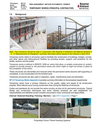
- 1. Procedure : SP 3.5 RISK ASSESSMENT / METHOD STATEMENTS / PERMITS Issue: B/SS2 Sys. Date: 01.10.11 Sheet: 1 of 10 TEMPORARY WORKS (PRINCIPAL CONTRACTOR) Site Services 1.0 Background Note: This procedure should be read in conjunction with Bowmer & Kirkland’s QA Manual Sections 3 – 5. A ‘Requirements for Designers’ summary document will be issued to the Intranet in early 2012. Temporary works refers to structures used to facilitate the construction of buildings, bridges, tunnels, and other above and below-ground facilities by providing access, support, and protection for the facility, workers and the public. Temporary works is defined in BS5975: 2008 as ‘works that allow, or enable construction of, protect, support or provide access to, the permanent works and which might or might not remain in place at the completion of the works’. These structures are dismantled and removed when the permanent works become self-supporting or completed, or are incorporated into the finished work. Temporary structures are also used in inspection, repair, maintenance work and demolition. SP 3.5 Temporary Works Appendix A provides summary information on the procedure requirements: Temporary works have a primary influence on the quality, safety and speed of all construction projects. More failures occur during construction than during the lifetimes of structures. Codes and standards do not provide the same scrutiny as they do for permanent structures. Typical design and construction techniques and some industry practices are well established, but responsibilities and liabilities remain complex and present many contractual and legal pitfalls. Internal / External Hoarding / Fencing / Barriers – see SP3.5 Appendix A Page 1 Proprietary Fence / Panel Hoarding Systems
- 2. Procedure : SP 3.5 RISK ASSESSMENT / METHOD STATEMENTS / PERMITS Issue: B/SS2 Sys. Date: 01.10.11 Sheet: 2 of 10 TEMPORARY WORKS (PRINCIPAL CONTRACTOR) Site Services ‘Scratch Built’ Hoarding e.g. posts concreted, box / barrel / bag kentledge Ground Excavations & Ground Bearing Capacity Engineering – see SP3.5 Appendix A Page 1 Ground- Fill / Stabilisation, Bearing Capacity, Track mats etc. Structures– see SP3.5 Appendix A Page 2 2.0 Bowmer & Kirkland Health & Safety Procedures The following may be defined as ‘temporary works’ in HSE Guidance but are to be managed in accordance with the specific, dedicated procedure listed below for Bowmer & Kirkland Projects. The procedures include requirements for design checks, calculations and inspections as necessary: Site fencing / hoarding inc. internal / sign boards SP 9.15 For proprietary systems requiring a design check (e.g. wind loading) and designed temporary works excluding specialist, major works e.g. in-situ concrete frame construction the process will need to be recorded to demonstrate compliance with the CDM Regulations. SPF 420 Authority to Proceed Note: SPF 107 withdrawn See section 3.3 Authority to Proceed Permit to Work Procedures. Note: this is not a Permit to Work or Permit to Load / Dismantle for falsework / formwork. The specialist concrete frame / civil engineering Contractor should provide these documents as part of their safe system of work. SPF 420 Authority to Proceed is to be used as record of the temporary works process. SP 3.5 Appendix A identifies the documentation requirements for all temporary works normally conducted on Bowmer & Kirkland projects. 2.1 Site Services Site Services must ensure that the information required and necessary checks have been provided to the site / TWC so the SPF 420 can be completed. Normally this will be in the form of a drawing and may include evidence / results from calculations. Further advice can be obtained from the Safety Department on the requirements for any other temporary works undertaken.
- 3. Procedure : SP 3.5 RISK ASSESSMENT / METHOD STATEMENTS / PERMITS Issue: B/SS2 Sys. Date: 01.10.11 Sheet: 3 of 10 TEMPORARY WORKS (PRINCIPAL CONTRACTOR) Site Services START Does Temporary Works No Procedure SP 3.5 Apply? See Appendix A ’TW Register’ Yes TWC completes SPF 420: Header + Sections 1-7a Contractor installs Temporary Works in accordance with Method Statement / Safe System Of Work TWC receives Handover Document / completes Pre-use Inspection TWC completes SPF 420 Section 7b see SP 3.5 Appendix A ‘Handover’ Note: This form must be completed prior to use of Temporary Works Temporary works may be used Competent Person completes and records inspections (see SP 3.5 Appendix A ‘Inspections’) Is permission required to load / dismantle TW or Yes TWC prior to handover / use? completes see SP 3.5 Appendix A SPF 420 ‘Loading / Dismantling’ Section 7C No PROCEED A ‘temporary works register’ is not a Bowmer & Kirkland form. The equivalent information is available from: Contracted scope of works / scope of service / sub-contract pre-contract meeting (MPF 3.3); Design Team Meeting Minutes (MPF 4.7); Drawing register / portal; or Procedure compliance SPF 420 Authority to Proceed Temporary Works Form (Filed at Management System Section 9.2).
- 4. Procedure : SP 3.5 RISK ASSESSMENT / METHOD STATEMENTS / PERMITS Issue: B/SS2 Sys. Date: 01.10.11 Sheet: 4 of 10 TEMPORARY WORKS (PRINCIPAL CONTRACTOR) Site Services The ATP sign-off creates hold points prior to: Installation & Commissioning Use / Loading Dismantling / Handover This form will identify: The Contractor and Supplier / Designer The scope of works (‘design brief’) Designer / Checker and drawing or Data Sheet for proprietary equipment. Sequence of work and other precautions, and Restrictions on / Permitted Loadings in service. Fully designed, complex integrated works should be managed within the permanent works through procurement, design and construction in Quality Management Procedures. 3.0 Design principles Under the CDM Regulations Designers and Engineers are required to eliminate or reduce risks through their designs. They must take account of the buildability of their designs including any temporary works and the working space required for plant, personnel and materials during construction. Incorporation of permanent works to eliminate or reduce the need for temporary works will eliminate additional risks, costs and construction processes from the programme. There must always be liaison and coordination with permanent works designer / structural engineer for works involving foundations and structures to ensure there no clashes or imposed loads which may affect or adversely load the permanent or temporary works. The preparation and checking of design calculations, drawings and specification should be undertaken with similar rigour to the procedures applied to the design of the permanent works. Temporary works designers include the manufacturers and suppliers of proprietary temporary works equipment (where design criteria may be met via standard configurations), as well as specialist structural engineers or designers. Management of ‘procurement’ (MP 3.0), ‘design’ (MP 4.0) and ‘construction’ (MP 5.0) forms part of Bowmer & Kirkland’s Quality Management System for delivering permanent works. See also ‘CDM: Requirements for Designers’ document. In order to ensure the strength and stability of any temporary works structure, there are three fundamental aspects that need to be considered which can be simplified as follows: Foundations – the ability of the ground to carry the loads transmitted from the temporary works structure without failure or excessive deformation or settlement. Structural integrity – the ability of the temporary works structure itself to carry and transmit loads to the ground via the foundations without failure of the structural elements, including fixings and connections (e.g. by buckling, bending, shear, tension, torsion), and without excessive deflection. Stability – the ability of the temporary works structure to withstand horizontal or lateral loading without sway, overturning or sliding failure (stability may be inherent in the temporary works structure itself or provided by the permanent works).
- 5. Procedure : SP 3.5 RISK ASSESSMENT / METHOD STATEMENTS / PERMITS Issue: B/SS2 Sys. Date: 01.10.11 Sheet: 5 of 10 TEMPORARY WORKS (PRINCIPAL CONTRACTOR) Site Services The design of the temporary works should be based on the agreed ‘design brief’. This will usually form part of the scope of service / scope of works / scheme requirements of the specialist Consultant, Contractor or Supplier. In most cases this will be very simple and covered in the Contractor / Supplier scope of works defined in the sub-contract and subsequent method statement. In more complicated situations the brief may remain simple e.g. support adjoining building, construct base in location X, etc. The brief should be clarified and developed through the sub-contract pre- contract meeting (MPF 3.3), Design Team Meetings (MPF 4.7) and associated minutes. Any alteration or modification of the design by the designer outside the original scope of work should be reported and justified to the Project Manager / Design Team. 4.0 Requirements for Designers / Engineers / Sub-contractors Relevant requirements of Bowmer & Kirkland Group procedures for Health & Safety, Quality and Environmental Management should be communicated to the Designer, Consultant (including where novated nominated or directly appointed by the Client) and Supplier / Sub-contractor to ensure compliance. This is normally achieved by the issue of the ‘Safety Requirements for Contractors’ and / or ‘CDM: Requirements for Designers’ documents which are also available on the company’s website (www.bandk.co.uk). This information may be supplemented by issue of individual company procedures or specific instructions during meetings etc. As Bowmer & Kirkland is not a structural designer and does not employ in-house Chartered engineers, we are wholly dependent upon competent Professional advisors to demonstrate they have designed and delivered buildable and safe solutions for temporary and permanent works including: demonstrating an understanding of the required solution(s) have regard to overall buildability for health, safety and quality; ensuring a suitably competent temporary works designer/adviser is in place to supply an engineered solution Identifying and complying with all relevant design codes, Building Regulations, British Standards and other guidance and codes of practice. advising Bowmer & Kirkland if they are not competent to complete any aspect of the temporary works design, coordinating other parties / suppliers where they are the ‘lead’ structural designer / engineer, identifying any information which requires clarification or further survey information; ensuring adequate information flow, design checking to an appropriate level, suitable verification of correct erection of the temporary works and overseeing and coordinating the whole process including ensuring that the temporary works are constructed in accordance with the ‘Approved’ drawings. Consideration of working space for plant and personnel during installation, use, inspection and removal, plant requirements, lifting operations, component weights, etc. Updating information on the Project Portal or other document control system used on site. Identifying sequencing of installation / removal and any hold points where inspections or checks are required during construction or prior to use / dismantling, etc. Identifying regular inspections required and providing on-going support for the Project Management
- 6. Procedure : SP 3.5 RISK ASSESSMENT / METHOD STATEMENTS / PERMITS Issue: B/SS2 Sys. Date: 01.10.11 Sheet: 6 of 10 TEMPORARY WORKS (PRINCIPAL CONTRACTOR) Site Services Where the design, or part of it, is carried out by specialist sub-contractors or supplier, these requirements will still apply and competence, experience, and insurance should still be reviewed prior to installation / construction through MPF 3.18. The designer, sub-contractor and supplier of temporary works equipment shall liaise with the all parties so that the practical requirements for the works are fully met and the actual conditions of loading are taken into account in the design and detailing. This is important as the scope and requirements (design brief) may develop during the Project and a number of alternative solutions evaluated to select the ‘best’ solution. Specific detail must be incorporated into the method statements to identify safety critical methods and sequence of construction, any hold points, and measures to ensure sufficient working space and safety of personnel – particularly to manage the risks of falls, falling objects, overloading and structural failure or collapse. Sub-contractors, etc. involved on the construction or installation of temporary works, are required to: prepare and submit a suitable method statement incorporating the designer’s specification ensure they are working to the latest approved / issued drawings procure materials in accordance with the designer’s specification store materials appropriately to ensure they do not degrade or get damaged conduct inspections during construction in accordance with standard industry practice associated with the works and as specified / agreed with Bowmer & Kirkland and / or the designer provide suitable information or access to the works during the construction to Bowmer & Kirkland and / or the Designer to satisfy any agreed hold points notify Bowmer & Kirkland and / or the Designer of any deviation from the Designer’s specification or submitted method statement Where problems or a deviation in construction method, sequence or materials are identified then this is to be referred to the Designer. This may be verbally, be e-mail or other formal means as agreed with the Design team during the Design Team Meetings (MPF 4.7). Whilst in many cases such issues can be closed out by site visit or verbal instruction, a formal response by e-mail is required for clarity and as a formal record of design change for any deviation from the Designer’s documented instructions. Verbal instruction is no longer adequate, without formal confirmation. If you can’t be certain the Temporary Works are suitable and safe – stop work and refer to the specialist engineer or their supervisor / manager. The Designer / Engineer must cooperate with any permanent works or other designer and must advise Bowmer & Kirkland where a design change is substantial enough to require further design or calculation checks for validation or where works must be sequenced or substantially altered to achieve the design requirements. Designers / Engineers must ensure they report any concerns to Bowmer & Kirkland and provide appropriate advice and information relating to design changes including site instructions. These should be confirmed by e-mail, written instruction or revised drawings and reviewed at design team meetings.
- 7. Procedure : SP 3.5 RISK ASSESSMENT / METHOD STATEMENTS / PERMITS Issue: B/SS2 Sys. Date: 01.10.11 Sheet: 7 of 10 TEMPORARY WORKS (PRINCIPAL CONTRACTOR) Site Services 5.0 Drawings Drawings should be controlled, clearly labelled re issue number / date and construction issue drawings include the designer / engineer, and check designer engineer Authorisations / initials issued as ‘Checked’ / ‘Approved’. Where designers alter designs they will be required to carry out all necessary checks before issuing site instructions or amended drawings and advise the construction team on any particular requirements in implementing their design, including any specialist checks on configurations, dimensions, materials etc. Only the most up to date, Authorised (checked and approved) drawings should be issued and used for construction. The method for individual projects is agreed by the Design Team and is normally documented in the Design Team Meeting minutes (MPF 4.7). This is normally discussed with relevant sub-contractors during the sub-contractor pre-contract meeting (MPF 3.3). 6.0 Temporary Works Design (BS 5975:2008) This British Standard refers primarily to elements of specialist concrete construction and civil engineering including: Formwork is the generic name given to temporary molds which are constructed to contain wet concrete in order to form the required finished dimensions and surface quality. Falsework – a temporary structure used to support a permanent structure while it is not self- supporting, either in new construction or refurbishment e.g. to support horizontal formwork. BS5975: 2008 Part 1 identifies general principles relating to design and site control for temporary works which are relevant to Bowmer & Kirkland as a Management Contractor and are incorporated in this guidance. BS5975: 2008 describes the process as requiring: Appointment of a Temporary Works Co-coordinator (TWC); Identification of design / solution requirements e.g. scope of service or scope of works (a ‘design brief’); Production of a temporary works design (including a design risk assessment and a designer’s method statement where appropriate) incorporating all inspection requirements. Control and supervision of the erection, safe use, maintenance and dismantling of the temporary works including any specialist suppliers / contractors, sequencing, exclusion zones etc. Design work shall commence in sufficient time to ensure that all materials required are on site and checked as satisfactory by the date required on the Contract programme. Designs by a competent, experienced person. Designer competence check should be completed and recorded where appointed by Bowmer & Kirkland; Designer to carry any necessary PI Insurance. Designers / engineers are to have an ‘independent’ check of calculations and design principles (see table of Design Check Categories below). This may be by another ‘in-house’ engineer under an organisation’s QA procedures and should employ a different means of calculation. Independent ‘one man band’ temporary works engineers / designers should not carry out their own checks other than for simple or specialist cases (demolition, scaffolding designer, etc.)
- 8. Procedure : SP 3.5 RISK ASSESSMENT / METHOD STATEMENTS / PERMITS Issue: B/SS2 Sys. Date: 01.10.11 Sheet: 8 of 10 TEMPORARY WORKS (PRINCIPAL CONTRACTOR) Site Services BS 5975:2008 Design Checks Temporary works designs may be categorised to indicate the complexity/simplicity of the specific temporary works structure and the potential risk. See below for examples (the list is not exhaustive): Note: tower crane base design will normally be part of the foundation design for the permanent structure and is subject to SP 12.5. Kier Engineering Services will carry out checks for Kier Plant cranes; otherwise the designer will be expected to complete category 2 checks. Categories of design check BS 5975:2008 Cat Scope Comment Independence of checker 0 Restricted to standard solutions This applies to the use of standard This is a site issue; the check only, to ensure the site conditions solutions. may be carried out by do not conflict with the scope or another member of the site limitations of the chosen standard or design team. solution. 1 For simple designs. Such designs would be undertaken The check may be carried using simple methods of analysis and out by another member of the be in accordance with the relevant design team. standards, supplier’s technical literature or other reference publications. 2 On more complex or involved Designs where a considerable The check should be carried designs. degree of interpretation of loading or out by an individual not other information is required before involved in the design and the design. not consulted by the designer. 3 For complex or innovative These designs include unusual The check should be carried designs. designs or where significant out by another organisation departures from standards, novel methods of analysis or considerable exercise of engineering judgement are involved. Category 3 checks – are not normally applicable to Bowmer & Kirkland Projects. If there is any doubt please refer to the Health & Safety Department 7.0 BS 5975:2008 Temporary Works Coordinator (TWC) The TWC is a role responsible for ensuring / facilitating the correct communication of information between all parties and that procedures for the control of temporary works are implemented on site. As Principal Contractor Bowmer & Kirkland shall plan, monitor and coordinate the works. Supervision is carried out by the Contractor / Supplier. During tendering and design the role and responsibilities will be discharged by the Commercial and Contracts team and others including designers, consultants and specialist contractors or suppliers guided by the lead structural engineer, who may be a Client appointment / novated. The process happens as an integral part of the Bowmer & Kirkland Quality Management System Procedures. In practice the TWC appointment cannot exist until the Project site team are mobilised. Bowmer & Kirkland is not the designer, but is responsible for ensuring that a suitable temporary works design is prepared, checked and implemented on site in accordance with the relevant drawings and specification. When the Project commences on site and Contractors are appointed, a Temporary Works Coordinator (TWC) shall be appointed by the Contracts Manager to co-ordinate the process, assist in processing information requests and keep records in accordance with the Project Plan and Management System requirements e.g. drawing register on Project Portal.
- 9. Procedure : SP 3.5 RISK ASSESSMENT / METHOD STATEMENTS / PERMITS Issue: B/SS2 Sys. Date: 01.10.11 Sheet: 9 of 10 TEMPORARY WORKS (PRINCIPAL CONTRACTOR) Site Services The Appointment of the TWC will be evidenced on the Filing List, Responsibilities Form MPF 9.1. On complex projects there should be a nominated Deputy to cover holiday periods etc. Bowmer & Kirkland does not employ Chartered engineers, and the Project team members will not be fully experienced in the technical requirements of all temporary works. The TWC will attend a Management of Temporary Works training course delivered by a supplier approved by the Safety Department, e.g. Thomas Telford. Duties may be delegated to Contractors but responsibility remains with the TWC. 8.0 Temporary Works Supervisor (TWS) On larger sites, or where a number of subcontractors are involved, it may be appropriate for one or more Temporary Works Supervisors (TWS) to be appointed. A TWS should be responsible to the TWC and assist the TWC in the supervision of temporary works as delegated. This should be recorded monitored via the Role & Responsibilities Matrix and in the Internal Project Review minutes. 9.0 Inspections The HSE state that ‘Temporary Works Inspectors should come from an engineering background, but successful completion of an appropriate course may be acceptable, e.g. Scaffold Inspection course for checking basic scaffolding’. The selection and use of simple temporary works is a core skill and forms part of their training and competence for many trades e.g. groundworkers, civil engineers, builders, steel erectors etc. Bowmer & Kirkland Managers will attend technical training to assist in meeting their obligations. Specialist Suppliers and Contractors who have additional technical training, knowledge and specialist skills may be delegated to carry out these inspections but site management retain responsibility for ensuring they are completed and remedial action closed out. It may be appropriate for the Contractor / Supplier to have a visiting Contracts or Safety Manager with authority over the site based team, carry out these checks. The Temporary Works Co-ordinator shall ensure inspection of the installation of the temporary works / equipment is completed by a competent person and recorded where necessary, throughout the course of its construction and is in compliance with the design and drawings. On completion of installation of the temporary works / equipment, a pre-use inspection shall be completed by a competent person. Any faults identified shall be rectified before loading / use. A hand over Certificate should be provided where applicable. This will be recorded at 7b on SPF 420 ATP temporary Works. Site Engineers and Managers should carry out normal management checks to ensure any drawing or method statement is observed by the contractor, and for use of correct specification materials and equipment, and dimensional tolerance in accordance with Bowmer & Kirkland Quality Management procedures. Progress photographs should be maintained to record construction is compliant with design, together with contractor’s normal records of material strengths, inspection and test. Specific pre-use, daily, weekly and other Inspections may be delegated to competent personnel from the specialist contractor / engineer. Further Inspections may be required prior to loading permanent or temporary works, removal of temporary works or commissioning as permanent works (including test or Statutory Inspection records). This will be recorded on SPF 420 ATP temporary Works.
- 10. Procedure : SP 3.5 RISK ASSESSMENT / METHOD STATEMENTS / PERMITS Issue: B/SS2 Sys. Date: 01.10.11 Sheet: 10 of 10 TEMPORARY WORKS (PRINCIPAL CONTRACTOR) Site Services Should any anchor point, scaffold tie, foundation (for lifting equipment), etc. be re-commissioned it will require engineering checks and testing to ensure it is suitable for the intended temporary works and loading and a regime of normal in-service inspections. 10.0 Temporary Works in Long Term Use Temporary works can deteriorate over time and a regime of periodic inspections must be put in place. The routine inspections, in accordance with designer guidelines, must consider long term deterioration of materials such as timber wedges, timber fence posts, the integrity of ties, stability of embankments etc. Records of these routine inspections must be kept, and may be included in the records of other relevant inspections e.g., hoarding, scaffolding, etc. 11.0 ‘Inherited’ / ‘Legacy’ Temporary Works Where existing temporary works are taken over on a site e.g. hoarding, retaining works, etc., enquiries should be made to determine the design criteria, installation and inspection information and evaluate the integrity and suitability of the temporary works / equipment for the proposed works. This information should form part of the pre-construction information from the CDMC; otherwise they should make arrangements to commission suitable surveys and inspections, and the scope and timescale for any remedial works. Until this information is available any hoarding / fence remains the responsibility of the site owner or Permit / Licence holder e.g. demolition Contractor / previous Principal Contractor. A visual inspection and dilapidation photos should be prepared and any areas of immediate or serious concern notified to the CDMC / Client. Where Bowmer & Kirkland are required commence operations without this information being received then this should be referred to the Safety Department for advice, a formal risk assessment may be required to ensure safety of the workforce. To comply with CDM Regulations where we are Principal Contractor daily inspections should take place and be recorded on SPF 306 Site Hoarding & Fencing Daily Inspection Record. The site should be secured with additional security, temporary fencing, etc. to maintain the boundary and to exclude unauthorised persons. If the CDMC is unable to obtain Designer Details, Design Brief / Design checks a full survey and remedial work should be instructed by the Client. Until adequate information is available the retained temporary works structure remains the ultimate responsibility of the Client / site owner or Permit / Licence holder e.g. demolition Contractor / previous Principal Contractor, who should be fulfilling on-going Inspection requirements for CDM Regulations compliance. A written report or ‘handover’ should be prepared by a competent engineer / Contractor prior to taking over the responsibility for maintenance and use of the temporary works. A visual inspection and dilapidation photos should be prepared and any areas of immediate or serious concern notified to the CDMC / Client. If necessary establish an exclusion zone and make the area safe until a Client instruction is received. Where works are left in place on completion of the Project / Phase etc. the CDMC should be advised of the designer, design and checks and any on-going inspection requirements, etc. as part of the Project Health & Safety File information. The CDMC should advise the Client on the appointment of a competent engineer or Contractor to fulfil their on-going Legal obligations and any security or insurance requirements. Further Guidance Please contact the Group Health & Safety Department Ext. 4498 or your Health & Safety Manager Advisor.