SlideShare uma empresa Scribd logo
1 de 42
Questions
1.   If the charge of 25C passes a given point in a circuit in a
     time of 125ms, determine the current in the circuit.
2.   A circuit delivers energy at a rate of 20W and the current
     is 10A. Determine the energy of each Colomb of charge in
     the circuit.
3.   A current of 5A flows in a resistor of resistance 8 ohm.
     Determine the rate of heat dissipation and also the heat
     dissipated in 30 seconds.
4.   A motor gives an output power of 20KWand operates with
     an efficiency of 80%.If the constant input voltage to the
     motor is 200V what is the constant supply current.
5.   A 200T train experiences wind resistance equivalent to
     62.5N/T. The operating efficiency of the driving motor is
     0.87 and        the    cost    of    electrical energy    is
     8rupees/kwh.What is the cost of energy required to make
     the train travel 1km. If the train is supplied at a constant
     voltage of 1.5kv and travels with a velocity of 80km/h what
     is the supply current.
5.    A resistor is marked first band brown, second band black,
      third band orange and no other band. What is its
      resistance and between what values does it lies.
6.    A 240V lamp is rated to pass a current f 0.25A. Calculate
      its power output. If a second similar lamp is connected in
      parallel to the lamp, calculate the supply current required
      to give the same power output in each lamp.
7.    A current of 3A flows through a 10ohm resistor, find
     1.   The power developed by the resistor
     2.   The energy dissipated in 5 minutes

5.    A conductor of 0.5mm diameter wire has a resistance of
      300ohm. Find the resistance of the same length of wire if
      its diameter were doubled.
6.    A coil is wound from a 10m length of copper wire having a
      cross sectional area of 1.0mm2. Calculate the resistance of
      the coil        (resistivity of cu 1.59X10⁻⁸)
Chapter 3- DC and AC theory
  3.2 AC circuits
  3.2.1   features of AC sinusoidal wave form for voltages and
          currents
  3.2.2   explanation of how other more complex wave forms are
          produced from sinusoidal wave forms
  3.2.3   R, L, C circuits (eg reactance of R, L and C components,
          equivalent impedance and admittance for R-L and R-C
          circuits)
  3.2.4   high or low pass filters
  3.2.5   power factor
  3.2.6   true and apparent power
  3.2.7   resonance for circuits containing a coil and capacitor
          connected either in series or parallel
  3.2.8   resonant frequency
  3.2.9   Q-factor of resonant circuit
Features of AC sinusoidal waveform
• Wave – A disturbance traveling through a medium.
• Waveform – A graphic representation of a wave.
   – Waveform depends on both movement and time.
   – A change in the vertical dimension of a signal is a result of a
     change in voltage.
• Frequency – The number of cycles of the waveform
  which occur in one second of time.
   – (Measured in hertz (Hz))
• Period – The time required to complete one cycle of a
  waveform.
   – (Measured in seconds, tenths of seconds, millisecond, or
     microseconds)
• Amplitude – Height of a wave
   – (Expressed in one of the following methods)
       • Peak
       • Peak-to-peak
       • Root-mean-square (rms)
• Peak – The maximum positive or negative deviation of a waveform
  from its zero reference level.
   – Sinusoidal waveforms are symmetrical
   – The positive peak value of sinusoidal will be equal to the value of the
     negative peak
• Peak-to-peak – The measurement from one peak to the other.
   – Sinusoidal waveform: If the positive peak value is 10 volts in magnitude,
     then the negative peak is also 10, therefore peak to peak is 20 volts.
   – Nonsinusoidal waveform: determined by adding magnitude of positive and
     negative peaks.
• Root-mean-square (rms)
   – Allows the comparison of ac and dc circuit values.
   – RMS values are the most common methods of specifying sinusoidal
     waveforms.
   – Almost all voltmeter and ammeters are calibrated so that they measure ac
     values in terms of RMS amplitude.
   – RMS value is also known as the effective value
       • Defined in terms of the equivalent heating effect of direct current.
       • RMS value of a sinusoidal voltage is equivalent to the value of a dc voltage
         which causes an equal amount of heat due to the circuit current flowing through
         resistance.
   – The rms value of a sinusoidal voltage is 70.7% or 0.707 of its peak
     amplitude value.
Types of waveforms
There are several classes of signals:
•   Continuous-time and discrete-time signals
    A signal that is specified for every value of time, t is a continuous-time
    signal. A signal that is specified only at discrete value of t , is a
    discrete-time signal
•   Analog and digital signals
    Analog signal is a signal whose amplitude can take on any value in a
    continuous range. Digital signal is a signal whose amplitude can take
    on only a finite number of values.
    Note: Analog is not necessary continuous time and digital need not to
    be discrete time
•   Periodic and non-periodic signals
    A periodic signal shows that the signal repeats itself indefinitely in the
    future and has repeated itself indefinitely in the past for a period of T.
    It starts from − ∞ to + ∞ . An aperiodic, or nonperiodic, is not periodic.
    There is no specific period for this signal
There are three types of signal operation:
(a) Time shifting
  g (T+t) is g( t) advanced (left-shifted) by T seconds and g(T−t ) is
  g(t) delayed (right shifted) by T seconds.

(b) Time scaling
  g (2t) is g (t) compressed by 2 seconds and g(t/2) is g(t) is
  expanded by 2 seconds. (time scaling factor can take only positive
  values)

(c) Time inversion
  Time inversion may be considered a special case of time scaling
  where scaling factor is equal to -1.
Few waveforms on oscilloscope


 Oscilloscope    Sine wave   square wave   triangular wave


• Oscilloscope is a device to observe the shape of
  the waveform and to measure the amplitude and
  period
• All above waves a periodic waveforms
• All complex periodic waveforms can be breakdown
  into a series of trigonometric waveforms (sine and
  cosine)
Fourier analysis
• In the study of communication systems, we are
  interested in frequency-domain description or
  spectrum of a signal.
• We need to know the amplitude and phase of
  each frequency component contained in the
  signal.
• We get this information by performing Fourier
  analysis on the signal.
  – Periodic signals: Fourier series
  – Aperiodic signals: Fourier transformation
Fourier series
In general, a Fourier series can be written as a series of
terms that include trigonometric functions with the
following mathematical expression:

or
RLC components
Component Resistor           Inductor       Capacitor
Symbol
Impedance R                  LS or Lωj      1/CS or
                                            1/Cωj
Phase shift   Voltage and    Current lags Current leads
              currents are   voltage by π/2 voltage by π/2
              in phase
Properties of RLC
• Resistors dissipate energy as heat
• Capacitances store charge. If a capacitance is shorted out
  the stored charge leaks off and its stored energy is lost.
• Inductances store current. If an inductive loop is opened
  the stored current stops and its stored energy is lost.
• Pure inductors and capacitors do not dissipate energy.
  Therefore only resistors are contributed to active power
  and inductance/capacitance are for reactive power.
• So what happens if we connect an inductance and a
  capacitance in series? Note that the capacitance sees a
  short circuit and the inductance sees an open circuit. So
  the capacitance will start to discharge, which creates a
  current through the inductance. And the inductance will
  push the current along until it is depleted by (re)charging
  the capacitance. The energy oscillates back and forth
Reactance resistance and impedance
•   Resistance is essentially friction against the motion of electrons.
     – It is present in all conductors to some extent (except superconductors!), most
       notably in resistors.
     – When alternating current goes through a resistance, a voltage drop is produced that
       is in-phase with the current.
     – Resistance is mathematically symbolized by the letter “R” and is measured in the
       unit of ohms (Ω)

•   Reactance is essentially inertia against the motion of electrons.
     – It is present anywhere electric or magnetic fields are developed in proportion to
       applied voltage or current, respectively; but most notably in capacitors and inductors.
     – When alternating current goes through a pure reactance, a voltage drop is produced
       that is 90o out of phase with the current.
     – Reactance is mathematically symbolized by the letter “X” and is measured in the unit
       of ohms (Ω).

•   Impedance is a comprehensive expression of any and all forms of opposition
    to electron flow, including both resistance and reactance.
     – It is present in all circuits, and in all components.
     – When alternating current goes through an impedance, a voltage drop is produced
       that is somewhere between 0o and 90o out of phase with the current.
     – Impedance is mathematically symbolized by the letter “Z” and is measured in the
       unit of ohms (Ω), in complex form.
Reactance
• Reactance is of two types
  – Inductive reactance


  – Capacitive reactance
• When taking current as a reference (refer to resistors) inductive reactance has a
  phase lead of π/2 while capacitive reactance has a phase lag of π/2.
∀ π/2 phase shift can be represented by j. Therefore impedance of a real inductor
  and real capacitor can be given as

         Z L = R + jX L = R + j 2πfL = R + jωL
                                  1          1          1
         Z C = R − jX C = R − j      = R+        = R+
                                2πfC      j 2πfC      j ωC

•   jω can be replaced by s
•   Reciprocal of the impedance is called the admittance and denoted by Y
Equivalent impedance
• Impedance can be manipulated as resistance,
  but the only difference is impedance is a
  complex number which composed of real and
  imaginary parts
Ohms law for AC
Series and parallel LC circuits


   Series RLC circuits   Parallel RLC circuits

            vS                  vS
  i=                      i=
       R + sL +1 sC          R +1 YLC

                            YLC = sC + 1 sL
Filters
•   Filters (active and passive/low pass and high pass)
     – Passive filters:
          • Composed of RLC elements
          • no external power supply is required for operation
     – Active filters:
          • Active elements such as op amps are used
          • For its operation external power supply is required
          • Can achieve a gain of more than one
     – Low pass filters
          • Low frequencies are allowed to pass while high frequencies are subjected to attenuation
     – High pass filters
          • High frequencies are allowed to pass while low frequencies are subjected to attenuation
•   It is sometimes desirable to have circuits capable of selectively filtering one
    frequency or range of frequencies out of a mix of different frequencies in a
    circuit. A circuit designed to perform this frequency selection is called a filter
    circuit, or simply a filter.
•   Applications
     – certain ranges of audio frequencies need to be amplified or suppressed for best
       sound quality and power efficiency
     – filter circuits is in the “conditioning” of non-sinusoidal voltage waveforms in power
       circuits
Low pass filters
• By definition, a low-pass filter is a circuit offering easy
  passage to low-frequency signals and difficult passage to
  high-frequency signals.
• There are two basic kinds of circuits capable of
  accomplishing this objective, and many variations of each
  one:
   – The inductive low-pass filter and
   – The capacitive low-pass filter
High pass filters
• offer easy passage of a high-frequency
  signal and difficult passage to a low-
  frequency signal
True reactive and apparent power
•   Reactive power
     – Reactive loads such as inductors and capacitors dissipate zero power, yet the fact
       that they drop voltage and draw current gives the deceptive impression that they
       actually do dissipate power.
     – This “phantom power” is called reactive power, and it is measured in a unit called
       Volt-Amps-Reactive (VAR), rather than watts.
     – The mathematical symbol for reactive power is (unfortunately) the capital letter Q.
•   Actual power
     – The actual amount of power being used, or dissipated, in a circuit is called true
       power,
     – It is measured in watts (symbolized by the capital letter P, as always).
•   Apparent power
     – The combination of reactive power and true power is called apparent power,
     – It is the product of a circuit’s voltage and current, without reference to phase angle.
     – Apparent power is measured in the unit of Volt-Amps (VA) and is symbolized by the
       capital letter S.
•   Power factor
     – When expressed as a fraction, this ratio between true power and apparent power is
       called the power factor for this circuit.
     – Poor power factor can be corrected, paradoxically, by adding another load to the
       circuit drawing an equal and opposite amount of reactive power, to cancel out the
       effects of the load’s inductive reactance. Inductive reactance can only be canceled
       by capacitive reactance.
Examples
Power triangle
Series resonance


 The features of series resonance:
  • The impedance is purely resistive, Z = R;
  • The supply voltage Vs and the current I are in phase (cosθ = 1)
  • The magnitude of the impedance is minimum;
  • The inductor voltage and capacitor voltage can be much more
    than the source voltage.
Vs (ω )                1                1 
  Z (ω ) = H (ω ) =        = R + jω L +      = R + j ωL −
                    I (ω )               jωC              ωC ÷
                                                              
           Resonance occurs when circuit is purely resistive
                 1                     1
Im( Z ) = ω L −    = 0 ⇒ ωo L =
                ωC                   ωoC
                              1
                      ωo =          Resonance Frequency
                              LC

                             1                 1
                ωo =            ,     fo =
                             LC              2π LC
Inductive reactance versus
                                          Capacitive reactance versus
          frequency.
                                                  frequency.


  Placing the frequency response of         ZT (total impedance) versus
     the inductive and capacitive        frequency for the series resonant
reactance of a series R-L-C circuit on
                                                        circuit.
        the same set of axes.
Bandwidth of series resonance
 Current versus frequency for the series resonant circuit.
                                                 Vm
                                I=I =
                                         R 2 + (ω L − 1 ) 2
                                                       ωC
                                                        Half Power Frequencies
                                                     Dissipated power is half of the
                                                     maximum value.


• The half-power frequencies ω      1   and ω2 can be obtained by setting,

           Z (ω1 ) = Z (ω2 ) = R 2 + (ω L − 1 ) 2 = 2 R
                                             ωC
                                            2
                                      Vm   
                                           ÷
                  P(ω1 ) = P (ω2 ) =      2
                                         2R
                             2                            2
                  R     R      1          R     R      1
           ω1 = −    +      ÷ +   , ω2 = +    +      ÷ +
                  2L    2 L  LC           2L    2 L  LC
 The width of the response is measured by the BANDWIDTH.
 BANDWIDTH is the difference between the half-power
frequencies.
                       B = ω2 − ω1

 Resonance frequency can be obtained from the half-power
frequencies.
                 ω o = ω1ω 2 , B = ω 2 − ω1

 The SHARPNESS of the resonance is measured by the
QUALITY FACTOR.
 QUALITY FACTOR is the ratio of the resonance frequency to the
bandwidth. The higher the Q the smaller is the bandwidth.
                                ωo
                           Q=
                                 B
Parallel resonance
 Resonance is a condition in an RLC circuit in which the capacitive and inductive
reactances are equal in magnitude, resulting in a purely resistive impedance.
 Parallel resonance circuit behaves similarly but in opposite fashion compared to
series resonant circuit.
 The admitance is minimum at resonance or impedance is maximum.


                                                                                1
                                                                      ωo =
                                                                                LC


                      Parallel resonant circuit.
                          I 1          1     1             1 
            Y = H (ω ) =    = + jωC +      = + j  ωC −
                          V R         jω L R              ωL ÷
             Resonance occurs when admitance is purely resistive
                          1                1              1
          Im(Y ) = ω L −     = 0 ⇒ ωo L =         ωo =         rad/sec
                         ωC               ωoC             LC
Parallel resonance
 At Resonance frequency:
1) Admittance is purely resistive.
2) The voltage and current are in phase.
3) The admittance Y(ω) is Minimum.
4) Inductor and capacitor currents can be much more than the source current.
            Im R
     IL =        = QI m    I C = ωo CI m R = QVm
            ωo L
Parallel resonance
                                                                              Im
                                                         V=V =
                                                                          2
                                                                       1
                                                                        ÷ + (ω C − 1 ) 2
                                                                       R           ωL


         Voltage versus frequency for the parallel resonant circuit.

 The half-power frequencies can be obtained as:
                                                     2
                                   1     1       1
                          ω1 = −      +       ÷ +
                                 2 RC    2 RC  LC
                                                     2
                                   1     1       1
                          ω2 = +      +       ÷ +
                                 2 RC    2 RC  LC
                                             1
               ω o = ω1ω 2 , B = ω 2 − ω1 =
                                            RC
Summary of series and parallel resonance circuits

      Characteristic     Series circuit               Parallel circuit


            ωo                   1                             1
                                 LC                            LC
             Q               ωo L      1                 R
                                  or                         or ωo RC
                              R      ωo RC              ωo L
             B                  ωo                             ωo
                                Q                              Q

          ω1, ω2                      1 2   ωo                  1 2   ω
                        ωo   1 + (      ) ±      ωo    1 + (      ) ± o
                                     2Q     2Q                 2Q    2Q

       Q ≥ 10, ω1, ω2                  B                            B
                                ωo ±                       ωo ±
                                       2                            2
Questions
• An alternating current of sinusoidal waveform has an rms
  value of 10A. What are the peak value over one cycle
• An alternating voltage has the equation v=141.4sin377t;
  what are the values of
   – Rms voltage
   – Frequency
   – The instantaneous voltage when t=3ms
• The instantaneous value of two alternating voltages are
  represented respectively by v1=60sin θ volts and
  v2=40sin(θ-π/3) volts. Derive an expression for the
  instantaneous value of
   – The sum
   – The difference of these voltages
•   A resistance of 7ohm is connected in series with a pure inductance of
    31.4mH and the circuit is connected to a 100V, 50Hz sinusoidal
    supply. Calculate
     – The circuit current
     – The phase angle
•   A pure inductance of 318mH is connected in series with a pure
    resistance of 75 ohms. The circuit is supplied from a 5Hz sinusoidal
    source and the voltage across the 75ohm resistor is found to be
    150V. Calculate the supply voltage.
•   A coil having both resistance and inductance, has a total effective
    impedance of 50ohm and the phase angle of the current through it
    with respect to the voltage across it is 450 lag. The coil connected in
    series with a 40ohm resistor across a sinusoidal supply. The circuit
    current is 3A; by constructing a phasor diagram, estimate the supply
    voltage and the circuit phase angle.
•   A 30µF capacitor is connected across a 400V, 50Hz supply.
    Calculate
     – The reactance of capacitor
     – The current
•   A 8µF capacitor takes a current1A when the alternating voltage applied across
    it is 250V. Calculate
     – The frequency of the applied voltage
     – Resistance to be connected in series with the capacitor to reduce the current in the
       circuit to 0.5A at the same frequency
     – The phase angle of the resulting circuit
•   A metal filament lamp rated at 750W, 100V is to be connected in series with a
    capacitor across a 230V, 50Hz supply. Calculate
     – The capacitance required
     – The phase angle between the current and the supply voltage
•   A circuit having a resistance 12Ω, an inductance of 0.15H and a capacitance
    of 100µF in series, is connected across a 100V, 50Hz supply. Calculate the
     – Impedance
     – Current
•   Three branches possessing a resistance of 50Ω, an inductance of 0.15H and
    a capacitance of 100µF respectively, are connected in parallel across a 100V,
    50Hz supply. Calculate the
     – Current in each branch
     – Supply current
     – Phase angle between the supply current and the supply voltage
•   A coil of resistance 50 Ω and inductance 0.318H is connected in parallel with a
    circuit comprising a 75 Ω resistor in series with a 159µF capacitor. The
    resulting circuit is connected to 1 240V, 50Hz ac supply. Calculate
     – The supply current
     – The circuit impedance, resistance and reactance
•   A coil having a resistance of 6 Ω and an inductance of 0.03H is connected
    across a 50V, 60Hz supply. Calculate
     – The current
     – The phase angle between the current and the applied voltage
     – The apparent power
     – The active power
•   An inductor coil is connected to a supply of 250V at 50Hz and takes a current
    of 5A. The coil dissipates 750W. Calculate
     – The resistance and the inductance of the coil
     – The power factor of the coil
•   A single phase motor operating off a 400V, 50Hz supply is developing 10kW
    with an efficiency of 84% and power factor of 0.7 lagging. Calculate
     – The input apparent power
     – The active and reactive components of the current
     – The reactive power
• A coil of resistance 5 Ω and inductance 1mH is connected in series
  with an 0.2µF capacitor. The circuit is connected to a 2V, variable
  frequency supply. Calculate the frequency at which resonance occurs,
  the voltage across the coil and the capacitor at this frequency and the
  Q factor of the circuit.
• A tuned circuit consisting of a coil having an inductance of 200µH and
  a resistance of 20 Ω in parallel with a variable capacitor is connected
  in series with a resistor of 8k Ω across a 60V supply having a
  frequency of 1MHz. Calculate
    – The value of C to give resonance
    – The dynamic impedance and the Q factor of the tumed circuit
    – The current in each branch
• A coil of 1kΩ resistance and 0.15H inductance is connected in parallel
  with a variable capacitor across a 2V, 10kHz ac supply. Calculate
    – The capacitance of the capacitor when the supply current is a minimum
    – The effective impedance of the network
    – The supply current

Mais conteúdo relacionado

Mais procurados

Mais procurados (19)

ac circuit
ac circuitac circuit
ac circuit
 
Ac single phase
Ac single phaseAc single phase
Ac single phase
 
Series parallel resonance circuit
Series parallel resonance circuitSeries parallel resonance circuit
Series parallel resonance circuit
 
Resonance in R-L-C circuit
Resonance in R-L-C circuitResonance in R-L-C circuit
Resonance in R-L-C circuit
 
Unit 2 resonance circuit
Unit 2 resonance circuitUnit 2 resonance circuit
Unit 2 resonance circuit
 
Series parallel ac rlc networks
Series parallel ac rlc networksSeries parallel ac rlc networks
Series parallel ac rlc networks
 
Circ rlc paralel
Circ rlc paralelCirc rlc paralel
Circ rlc paralel
 
resonance circuits
 resonance circuits resonance circuits
resonance circuits
 
R-L-C circuit
R-L-C circuitR-L-C circuit
R-L-C circuit
 
12
1212
12
 
Series parallel ac networks
Series parallel ac networksSeries parallel ac networks
Series parallel ac networks
 
resonance/electrical networks
resonance/electrical networksresonance/electrical networks
resonance/electrical networks
 
Ch12 ln
Ch12 lnCh12 ln
Ch12 ln
 
Et201 chapter3 sinusoidal steady state circuit analysis
Et201 chapter3 sinusoidal steady state circuit analysisEt201 chapter3 sinusoidal steady state circuit analysis
Et201 chapter3 sinusoidal steady state circuit analysis
 
Ac fundamentals
Ac fundamentalsAc fundamentals
Ac fundamentals
 
Ac circuits notes
Ac circuits   notesAc circuits   notes
Ac circuits notes
 
Elektronika (12)
Elektronika (12)Elektronika (12)
Elektronika (12)
 
Analysis of Phasor Diagram
Analysis of Phasor Diagram Analysis of Phasor Diagram
Analysis of Phasor Diagram
 
AC circuit
AC circuitAC circuit
AC circuit
 

Semelhante a Engineering science lesson 9

Intro to Electricity.ppt
Intro to Electricity.pptIntro to Electricity.ppt
Intro to Electricity.pptjohnjacobcabal
 
Intro to Electricity.pdf
Intro to Electricity.pdfIntro to Electricity.pdf
Intro to Electricity.pdfDavidKimunyan
 
Introduction to Electricity
Introduction to Electricity Introduction to Electricity
Introduction to Electricity johny renoald
 
lec 8 and 9 single phase transformer.pptx
lec 8 and 9 single phase transformer.pptxlec 8 and 9 single phase transformer.pptx
lec 8 and 9 single phase transformer.pptxssuser76a9bc
 
Chapter 11 physics
Chapter 11 physicsChapter 11 physics
Chapter 11 physicsKrishna Gali
 
Current Electricity and Effects of Current
Current Electricity and Effects of CurrentCurrent Electricity and Effects of Current
Current Electricity and Effects of CurrentOleepari
 
chapter_33_alternating_current_circuits_0.pptx
chapter_33_alternating_current_circuits_0.pptxchapter_33_alternating_current_circuits_0.pptx
chapter_33_alternating_current_circuits_0.pptxGodspower Bruno, GMNSE
 
Engineering science lesson 8 1
Engineering science lesson 8 1Engineering science lesson 8 1
Engineering science lesson 8 1Shahid Aaqil
 
Engineering science lesson 8
Engineering science lesson 8Engineering science lesson 8
Engineering science lesson 8Shahid Aaqil
 
HVac transmssion lines systems.ppt
HVac transmssion lines systems.pptHVac transmssion lines systems.ppt
HVac transmssion lines systems.pptabidSherazi
 
Introduction to Alternating Currents AC Circuits
Introduction to Alternating Currents AC CircuitsIntroduction to Alternating Currents AC Circuits
Introduction to Alternating Currents AC Circuitsxdarlord
 
AC FUNDAMENTALS.pptx
AC FUNDAMENTALS.pptxAC FUNDAMENTALS.pptx
AC FUNDAMENTALS.pptxroshan375533
 
Ac circuits 15 april 2013(1)
Ac circuits 15 april 2013(1)Ac circuits 15 april 2013(1)
Ac circuits 15 april 2013(1)Malusela Ndivhuwo
 

Semelhante a Engineering science lesson 9 (20)

Intro to Electricity.ppt
Intro to Electricity.pptIntro to Electricity.ppt
Intro to Electricity.ppt
 
Intro to Electricity.pdf
Intro to Electricity.pdfIntro to Electricity.pdf
Intro to Electricity.pdf
 
ELECTRICITY.ppt-converted.pptx
ELECTRICITY.ppt-converted.pptxELECTRICITY.ppt-converted.pptx
ELECTRICITY.ppt-converted.pptx
 
Introduction to Electricity
Introduction to Electricity Introduction to Electricity
Introduction to Electricity
 
Lesson2
Lesson2Lesson2
Lesson2
 
lec 8 and 9 single phase transformer.pptx
lec 8 and 9 single phase transformer.pptxlec 8 and 9 single phase transformer.pptx
lec 8 and 9 single phase transformer.pptx
 
Chapter 11 physics
Chapter 11 physicsChapter 11 physics
Chapter 11 physics
 
Current Electricity and Effects of Current
Current Electricity and Effects of CurrentCurrent Electricity and Effects of Current
Current Electricity and Effects of Current
 
Intro to Ham Radio 101
Intro to Ham Radio 101Intro to Ham Radio 101
Intro to Ham Radio 101
 
Transformer
TransformerTransformer
Transformer
 
Ac circuits
Ac circuitsAc circuits
Ac circuits
 
chapter_33_alternating_current_circuits_0.pptx
chapter_33_alternating_current_circuits_0.pptxchapter_33_alternating_current_circuits_0.pptx
chapter_33_alternating_current_circuits_0.pptx
 
Engineering science lesson 8 1
Engineering science lesson 8 1Engineering science lesson 8 1
Engineering science lesson 8 1
 
Engineering science lesson 8
Engineering science lesson 8Engineering science lesson 8
Engineering science lesson 8
 
HVac transmssion lines systems.ppt
HVac transmssion lines systems.pptHVac transmssion lines systems.ppt
HVac transmssion lines systems.ppt
 
Introduction to Alternating Currents AC Circuits
Introduction to Alternating Currents AC CircuitsIntroduction to Alternating Currents AC Circuits
Introduction to Alternating Currents AC Circuits
 
Std10 Electricity
Std10 ElectricityStd10 Electricity
Std10 Electricity
 
AC FUNDAMENTALS.pptx
AC FUNDAMENTALS.pptxAC FUNDAMENTALS.pptx
AC FUNDAMENTALS.pptx
 
TLW_Unit I material pdf.ppt
TLW_Unit I material pdf.pptTLW_Unit I material pdf.ppt
TLW_Unit I material pdf.ppt
 
Ac circuits 15 april 2013(1)
Ac circuits 15 april 2013(1)Ac circuits 15 april 2013(1)
Ac circuits 15 april 2013(1)
 

Mais de Shahid Aaqil

Engineering science lesson 5
Engineering science lesson 5Engineering science lesson 5
Engineering science lesson 5Shahid Aaqil
 
Engineering science lesson 4
Engineering science lesson 4Engineering science lesson 4
Engineering science lesson 4Shahid Aaqil
 
Engineering science lesson 1
Engineering science lesson 1Engineering science lesson 1
Engineering science lesson 1Shahid Aaqil
 
Engineering science lesson 6 1
Engineering science lesson 6 1Engineering science lesson 6 1
Engineering science lesson 6 1Shahid Aaqil
 
Engineering science lesson 11
Engineering science lesson 11Engineering science lesson 11
Engineering science lesson 11Shahid Aaqil
 
Engineering science lesson 10
Engineering science lesson 10Engineering science lesson 10
Engineering science lesson 10Shahid Aaqil
 
Engineering science lesson 7
Engineering science lesson 7Engineering science lesson 7
Engineering science lesson 7Shahid Aaqil
 
Engineering science lesson 6 2
Engineering science lesson 6 2Engineering science lesson 6 2
Engineering science lesson 6 2Shahid Aaqil
 
Engineering science presentation final
Engineering science presentation finalEngineering science presentation final
Engineering science presentation finalShahid Aaqil
 
Engineering science lesson 3
Engineering science lesson 3Engineering science lesson 3
Engineering science lesson 3Shahid Aaqil
 
Engineering science lesson 2
Engineering science lesson 2Engineering science lesson 2
Engineering science lesson 2Shahid Aaqil
 
Engineering science lesson 4
Engineering science lesson 4Engineering science lesson 4
Engineering science lesson 4Shahid Aaqil
 
Engineering science lesson 1
Engineering science lesson 1Engineering science lesson 1
Engineering science lesson 1Shahid Aaqil
 

Mais de Shahid Aaqil (13)

Engineering science lesson 5
Engineering science lesson 5Engineering science lesson 5
Engineering science lesson 5
 
Engineering science lesson 4
Engineering science lesson 4Engineering science lesson 4
Engineering science lesson 4
 
Engineering science lesson 1
Engineering science lesson 1Engineering science lesson 1
Engineering science lesson 1
 
Engineering science lesson 6 1
Engineering science lesson 6 1Engineering science lesson 6 1
Engineering science lesson 6 1
 
Engineering science lesson 11
Engineering science lesson 11Engineering science lesson 11
Engineering science lesson 11
 
Engineering science lesson 10
Engineering science lesson 10Engineering science lesson 10
Engineering science lesson 10
 
Engineering science lesson 7
Engineering science lesson 7Engineering science lesson 7
Engineering science lesson 7
 
Engineering science lesson 6 2
Engineering science lesson 6 2Engineering science lesson 6 2
Engineering science lesson 6 2
 
Engineering science presentation final
Engineering science presentation finalEngineering science presentation final
Engineering science presentation final
 
Engineering science lesson 3
Engineering science lesson 3Engineering science lesson 3
Engineering science lesson 3
 
Engineering science lesson 2
Engineering science lesson 2Engineering science lesson 2
Engineering science lesson 2
 
Engineering science lesson 4
Engineering science lesson 4Engineering science lesson 4
Engineering science lesson 4
 
Engineering science lesson 1
Engineering science lesson 1Engineering science lesson 1
Engineering science lesson 1
 

Último

Measures of Dispersion and Variability: Range, QD, AD and SD
Measures of Dispersion and Variability: Range, QD, AD and SDMeasures of Dispersion and Variability: Range, QD, AD and SD
Measures of Dispersion and Variability: Range, QD, AD and SDThiyagu K
 
Introduction to Nonprofit Accounting: The Basics
Introduction to Nonprofit Accounting: The BasicsIntroduction to Nonprofit Accounting: The Basics
Introduction to Nonprofit Accounting: The BasicsTechSoup
 
Grant Readiness 101 TechSoup and Remy Consulting
Grant Readiness 101 TechSoup and Remy ConsultingGrant Readiness 101 TechSoup and Remy Consulting
Grant Readiness 101 TechSoup and Remy ConsultingTechSoup
 
APM Welcome, APM North West Network Conference, Synergies Across Sectors
APM Welcome, APM North West Network Conference, Synergies Across SectorsAPM Welcome, APM North West Network Conference, Synergies Across Sectors
APM Welcome, APM North West Network Conference, Synergies Across SectorsAssociation for Project Management
 
Call Girls in Dwarka Mor Delhi Contact Us 9654467111
Call Girls in Dwarka Mor Delhi Contact Us 9654467111Call Girls in Dwarka Mor Delhi Contact Us 9654467111
Call Girls in Dwarka Mor Delhi Contact Us 9654467111Sapana Sha
 
9548086042 for call girls in Indira Nagar with room service
9548086042  for call girls in Indira Nagar  with room service9548086042  for call girls in Indira Nagar  with room service
9548086042 for call girls in Indira Nagar with room servicediscovermytutordmt
 
Advanced Views - Calendar View in Odoo 17
Advanced Views - Calendar View in Odoo 17Advanced Views - Calendar View in Odoo 17
Advanced Views - Calendar View in Odoo 17Celine George
 
Software Engineering Methodologies (overview)
Software Engineering Methodologies (overview)Software Engineering Methodologies (overview)
Software Engineering Methodologies (overview)eniolaolutunde
 
BASLIQ CURRENT LOOKBOOK LOOKBOOK(1) (1).pdf
BASLIQ CURRENT LOOKBOOK  LOOKBOOK(1) (1).pdfBASLIQ CURRENT LOOKBOOK  LOOKBOOK(1) (1).pdf
BASLIQ CURRENT LOOKBOOK LOOKBOOK(1) (1).pdfSoniaTolstoy
 
SOCIAL AND HISTORICAL CONTEXT - LFTVD.pptx
SOCIAL AND HISTORICAL CONTEXT - LFTVD.pptxSOCIAL AND HISTORICAL CONTEXT - LFTVD.pptx
SOCIAL AND HISTORICAL CONTEXT - LFTVD.pptxiammrhaywood
 
Russian Call Girls in Andheri Airport Mumbai WhatsApp 9167673311 💞 Full Nigh...
Russian Call Girls in Andheri Airport Mumbai WhatsApp  9167673311 💞 Full Nigh...Russian Call Girls in Andheri Airport Mumbai WhatsApp  9167673311 💞 Full Nigh...
Russian Call Girls in Andheri Airport Mumbai WhatsApp 9167673311 💞 Full Nigh...Pooja Nehwal
 
Accessible design: Minimum effort, maximum impact
Accessible design: Minimum effort, maximum impactAccessible design: Minimum effort, maximum impact
Accessible design: Minimum effort, maximum impactdawncurless
 
Web & Social Media Analytics Previous Year Question Paper.pdf
Web & Social Media Analytics Previous Year Question Paper.pdfWeb & Social Media Analytics Previous Year Question Paper.pdf
Web & Social Media Analytics Previous Year Question Paper.pdfJayanti Pande
 
Arihant handbook biology for class 11 .pdf
Arihant handbook biology for class 11 .pdfArihant handbook biology for class 11 .pdf
Arihant handbook biology for class 11 .pdfchloefrazer622
 
Nutritional Needs Presentation - HLTH 104
Nutritional Needs Presentation - HLTH 104Nutritional Needs Presentation - HLTH 104
Nutritional Needs Presentation - HLTH 104misteraugie
 
POINT- BIOCHEMISTRY SEM 2 ENZYMES UNIT 5.pptx
POINT- BIOCHEMISTRY SEM 2 ENZYMES UNIT 5.pptxPOINT- BIOCHEMISTRY SEM 2 ENZYMES UNIT 5.pptx
POINT- BIOCHEMISTRY SEM 2 ENZYMES UNIT 5.pptxSayali Powar
 
microwave assisted reaction. General introduction
microwave assisted reaction. General introductionmicrowave assisted reaction. General introduction
microwave assisted reaction. General introductionMaksud Ahmed
 
Mastering the Unannounced Regulatory Inspection
Mastering the Unannounced Regulatory InspectionMastering the Unannounced Regulatory Inspection
Mastering the Unannounced Regulatory InspectionSafetyChain Software
 

Último (20)

Measures of Dispersion and Variability: Range, QD, AD and SD
Measures of Dispersion and Variability: Range, QD, AD and SDMeasures of Dispersion and Variability: Range, QD, AD and SD
Measures of Dispersion and Variability: Range, QD, AD and SD
 
Introduction to Nonprofit Accounting: The Basics
Introduction to Nonprofit Accounting: The BasicsIntroduction to Nonprofit Accounting: The Basics
Introduction to Nonprofit Accounting: The Basics
 
Grant Readiness 101 TechSoup and Remy Consulting
Grant Readiness 101 TechSoup and Remy ConsultingGrant Readiness 101 TechSoup and Remy Consulting
Grant Readiness 101 TechSoup and Remy Consulting
 
APM Welcome, APM North West Network Conference, Synergies Across Sectors
APM Welcome, APM North West Network Conference, Synergies Across SectorsAPM Welcome, APM North West Network Conference, Synergies Across Sectors
APM Welcome, APM North West Network Conference, Synergies Across Sectors
 
Call Girls in Dwarka Mor Delhi Contact Us 9654467111
Call Girls in Dwarka Mor Delhi Contact Us 9654467111Call Girls in Dwarka Mor Delhi Contact Us 9654467111
Call Girls in Dwarka Mor Delhi Contact Us 9654467111
 
9548086042 for call girls in Indira Nagar with room service
9548086042  for call girls in Indira Nagar  with room service9548086042  for call girls in Indira Nagar  with room service
9548086042 for call girls in Indira Nagar with room service
 
Advanced Views - Calendar View in Odoo 17
Advanced Views - Calendar View in Odoo 17Advanced Views - Calendar View in Odoo 17
Advanced Views - Calendar View in Odoo 17
 
Mattingly "AI & Prompt Design: Structured Data, Assistants, & RAG"
Mattingly "AI & Prompt Design: Structured Data, Assistants, & RAG"Mattingly "AI & Prompt Design: Structured Data, Assistants, & RAG"
Mattingly "AI & Prompt Design: Structured Data, Assistants, & RAG"
 
Software Engineering Methodologies (overview)
Software Engineering Methodologies (overview)Software Engineering Methodologies (overview)
Software Engineering Methodologies (overview)
 
BASLIQ CURRENT LOOKBOOK LOOKBOOK(1) (1).pdf
BASLIQ CURRENT LOOKBOOK  LOOKBOOK(1) (1).pdfBASLIQ CURRENT LOOKBOOK  LOOKBOOK(1) (1).pdf
BASLIQ CURRENT LOOKBOOK LOOKBOOK(1) (1).pdf
 
SOCIAL AND HISTORICAL CONTEXT - LFTVD.pptx
SOCIAL AND HISTORICAL CONTEXT - LFTVD.pptxSOCIAL AND HISTORICAL CONTEXT - LFTVD.pptx
SOCIAL AND HISTORICAL CONTEXT - LFTVD.pptx
 
Mattingly "AI & Prompt Design: The Basics of Prompt Design"
Mattingly "AI & Prompt Design: The Basics of Prompt Design"Mattingly "AI & Prompt Design: The Basics of Prompt Design"
Mattingly "AI & Prompt Design: The Basics of Prompt Design"
 
Russian Call Girls in Andheri Airport Mumbai WhatsApp 9167673311 💞 Full Nigh...
Russian Call Girls in Andheri Airport Mumbai WhatsApp  9167673311 💞 Full Nigh...Russian Call Girls in Andheri Airport Mumbai WhatsApp  9167673311 💞 Full Nigh...
Russian Call Girls in Andheri Airport Mumbai WhatsApp 9167673311 💞 Full Nigh...
 
Accessible design: Minimum effort, maximum impact
Accessible design: Minimum effort, maximum impactAccessible design: Minimum effort, maximum impact
Accessible design: Minimum effort, maximum impact
 
Web & Social Media Analytics Previous Year Question Paper.pdf
Web & Social Media Analytics Previous Year Question Paper.pdfWeb & Social Media Analytics Previous Year Question Paper.pdf
Web & Social Media Analytics Previous Year Question Paper.pdf
 
Arihant handbook biology for class 11 .pdf
Arihant handbook biology for class 11 .pdfArihant handbook biology for class 11 .pdf
Arihant handbook biology for class 11 .pdf
 
Nutritional Needs Presentation - HLTH 104
Nutritional Needs Presentation - HLTH 104Nutritional Needs Presentation - HLTH 104
Nutritional Needs Presentation - HLTH 104
 
POINT- BIOCHEMISTRY SEM 2 ENZYMES UNIT 5.pptx
POINT- BIOCHEMISTRY SEM 2 ENZYMES UNIT 5.pptxPOINT- BIOCHEMISTRY SEM 2 ENZYMES UNIT 5.pptx
POINT- BIOCHEMISTRY SEM 2 ENZYMES UNIT 5.pptx
 
microwave assisted reaction. General introduction
microwave assisted reaction. General introductionmicrowave assisted reaction. General introduction
microwave assisted reaction. General introduction
 
Mastering the Unannounced Regulatory Inspection
Mastering the Unannounced Regulatory InspectionMastering the Unannounced Regulatory Inspection
Mastering the Unannounced Regulatory Inspection
 

Engineering science lesson 9

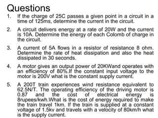
  • 1. Questions 1. If the charge of 25C passes a given point in a circuit in a time of 125ms, determine the current in the circuit. 2. A circuit delivers energy at a rate of 20W and the current is 10A. Determine the energy of each Colomb of charge in the circuit. 3. A current of 5A flows in a resistor of resistance 8 ohm. Determine the rate of heat dissipation and also the heat dissipated in 30 seconds. 4. A motor gives an output power of 20KWand operates with an efficiency of 80%.If the constant input voltage to the motor is 200V what is the constant supply current. 5. A 200T train experiences wind resistance equivalent to 62.5N/T. The operating efficiency of the driving motor is 0.87 and the cost of electrical energy is 8rupees/kwh.What is the cost of energy required to make the train travel 1km. If the train is supplied at a constant voltage of 1.5kv and travels with a velocity of 80km/h what is the supply current.
  • 2. 5. A resistor is marked first band brown, second band black, third band orange and no other band. What is its resistance and between what values does it lies. 6. A 240V lamp is rated to pass a current f 0.25A. Calculate its power output. If a second similar lamp is connected in parallel to the lamp, calculate the supply current required to give the same power output in each lamp. 7. A current of 3A flows through a 10ohm resistor, find 1. The power developed by the resistor 2. The energy dissipated in 5 minutes 5. A conductor of 0.5mm diameter wire has a resistance of 300ohm. Find the resistance of the same length of wire if its diameter were doubled. 6. A coil is wound from a 10m length of copper wire having a cross sectional area of 1.0mm2. Calculate the resistance of the coil (resistivity of cu 1.59X10⁻⁸)
  • 3. Chapter 3- DC and AC theory 3.2 AC circuits 3.2.1 features of AC sinusoidal wave form for voltages and currents 3.2.2 explanation of how other more complex wave forms are produced from sinusoidal wave forms 3.2.3 R, L, C circuits (eg reactance of R, L and C components, equivalent impedance and admittance for R-L and R-C circuits) 3.2.4 high or low pass filters 3.2.5 power factor 3.2.6 true and apparent power 3.2.7 resonance for circuits containing a coil and capacitor connected either in series or parallel 3.2.8 resonant frequency 3.2.9 Q-factor of resonant circuit
  • 4. Features of AC sinusoidal waveform • Wave – A disturbance traveling through a medium. • Waveform – A graphic representation of a wave. – Waveform depends on both movement and time. – A change in the vertical dimension of a signal is a result of a change in voltage. • Frequency – The number of cycles of the waveform which occur in one second of time. – (Measured in hertz (Hz)) • Period – The time required to complete one cycle of a waveform. – (Measured in seconds, tenths of seconds, millisecond, or microseconds) • Amplitude – Height of a wave – (Expressed in one of the following methods) • Peak • Peak-to-peak • Root-mean-square (rms)
  • 5. • Peak – The maximum positive or negative deviation of a waveform from its zero reference level. – Sinusoidal waveforms are symmetrical – The positive peak value of sinusoidal will be equal to the value of the negative peak • Peak-to-peak – The measurement from one peak to the other. – Sinusoidal waveform: If the positive peak value is 10 volts in magnitude, then the negative peak is also 10, therefore peak to peak is 20 volts. – Nonsinusoidal waveform: determined by adding magnitude of positive and negative peaks. • Root-mean-square (rms) – Allows the comparison of ac and dc circuit values. – RMS values are the most common methods of specifying sinusoidal waveforms. – Almost all voltmeter and ammeters are calibrated so that they measure ac values in terms of RMS amplitude. – RMS value is also known as the effective value • Defined in terms of the equivalent heating effect of direct current. • RMS value of a sinusoidal voltage is equivalent to the value of a dc voltage which causes an equal amount of heat due to the circuit current flowing through resistance. – The rms value of a sinusoidal voltage is 70.7% or 0.707 of its peak amplitude value.
  • 6.
  • 7.
  • 8.
  • 9. Types of waveforms There are several classes of signals: • Continuous-time and discrete-time signals A signal that is specified for every value of time, t is a continuous-time signal. A signal that is specified only at discrete value of t , is a discrete-time signal • Analog and digital signals Analog signal is a signal whose amplitude can take on any value in a continuous range. Digital signal is a signal whose amplitude can take on only a finite number of values. Note: Analog is not necessary continuous time and digital need not to be discrete time • Periodic and non-periodic signals A periodic signal shows that the signal repeats itself indefinitely in the future and has repeated itself indefinitely in the past for a period of T. It starts from − ∞ to + ∞ . An aperiodic, or nonperiodic, is not periodic. There is no specific period for this signal
  • 10. There are three types of signal operation: (a) Time shifting g (T+t) is g( t) advanced (left-shifted) by T seconds and g(T−t ) is g(t) delayed (right shifted) by T seconds. (b) Time scaling g (2t) is g (t) compressed by 2 seconds and g(t/2) is g(t) is expanded by 2 seconds. (time scaling factor can take only positive values) (c) Time inversion Time inversion may be considered a special case of time scaling where scaling factor is equal to -1.
  • 11. Few waveforms on oscilloscope Oscilloscope Sine wave square wave triangular wave • Oscilloscope is a device to observe the shape of the waveform and to measure the amplitude and period • All above waves a periodic waveforms • All complex periodic waveforms can be breakdown into a series of trigonometric waveforms (sine and cosine)
  • 12. Fourier analysis • In the study of communication systems, we are interested in frequency-domain description or spectrum of a signal. • We need to know the amplitude and phase of each frequency component contained in the signal. • We get this information by performing Fourier analysis on the signal. – Periodic signals: Fourier series – Aperiodic signals: Fourier transformation
  • 13. Fourier series In general, a Fourier series can be written as a series of terms that include trigonometric functions with the following mathematical expression: or
  • 14. RLC components Component Resistor Inductor Capacitor Symbol Impedance R LS or Lωj 1/CS or 1/Cωj Phase shift Voltage and Current lags Current leads currents are voltage by π/2 voltage by π/2 in phase
  • 15. Properties of RLC • Resistors dissipate energy as heat • Capacitances store charge. If a capacitance is shorted out the stored charge leaks off and its stored energy is lost. • Inductances store current. If an inductive loop is opened the stored current stops and its stored energy is lost. • Pure inductors and capacitors do not dissipate energy. Therefore only resistors are contributed to active power and inductance/capacitance are for reactive power. • So what happens if we connect an inductance and a capacitance in series? Note that the capacitance sees a short circuit and the inductance sees an open circuit. So the capacitance will start to discharge, which creates a current through the inductance. And the inductance will push the current along until it is depleted by (re)charging the capacitance. The energy oscillates back and forth
  • 16. Reactance resistance and impedance • Resistance is essentially friction against the motion of electrons. – It is present in all conductors to some extent (except superconductors!), most notably in resistors. – When alternating current goes through a resistance, a voltage drop is produced that is in-phase with the current. – Resistance is mathematically symbolized by the letter “R” and is measured in the unit of ohms (Ω) • Reactance is essentially inertia against the motion of electrons. – It is present anywhere electric or magnetic fields are developed in proportion to applied voltage or current, respectively; but most notably in capacitors and inductors. – When alternating current goes through a pure reactance, a voltage drop is produced that is 90o out of phase with the current. – Reactance is mathematically symbolized by the letter “X” and is measured in the unit of ohms (Ω). • Impedance is a comprehensive expression of any and all forms of opposition to electron flow, including both resistance and reactance. – It is present in all circuits, and in all components. – When alternating current goes through an impedance, a voltage drop is produced that is somewhere between 0o and 90o out of phase with the current. – Impedance is mathematically symbolized by the letter “Z” and is measured in the unit of ohms (Ω), in complex form.
  • 17. Reactance • Reactance is of two types – Inductive reactance – Capacitive reactance
  • 18. • When taking current as a reference (refer to resistors) inductive reactance has a phase lead of π/2 while capacitive reactance has a phase lag of π/2. ∀ π/2 phase shift can be represented by j. Therefore impedance of a real inductor and real capacitor can be given as Z L = R + jX L = R + j 2πfL = R + jωL 1 1 1 Z C = R − jX C = R − j = R+ = R+ 2πfC j 2πfC j ωC • jω can be replaced by s • Reciprocal of the impedance is called the admittance and denoted by Y
  • 19. Equivalent impedance • Impedance can be manipulated as resistance, but the only difference is impedance is a complex number which composed of real and imaginary parts
  • 21. Series and parallel LC circuits Series RLC circuits Parallel RLC circuits vS vS i= i= R + sL +1 sC R +1 YLC YLC = sC + 1 sL
  • 22. Filters • Filters (active and passive/low pass and high pass) – Passive filters: • Composed of RLC elements • no external power supply is required for operation – Active filters: • Active elements such as op amps are used • For its operation external power supply is required • Can achieve a gain of more than one – Low pass filters • Low frequencies are allowed to pass while high frequencies are subjected to attenuation – High pass filters • High frequencies are allowed to pass while low frequencies are subjected to attenuation • It is sometimes desirable to have circuits capable of selectively filtering one frequency or range of frequencies out of a mix of different frequencies in a circuit. A circuit designed to perform this frequency selection is called a filter circuit, or simply a filter. • Applications – certain ranges of audio frequencies need to be amplified or suppressed for best sound quality and power efficiency – filter circuits is in the “conditioning” of non-sinusoidal voltage waveforms in power circuits
  • 23. Low pass filters • By definition, a low-pass filter is a circuit offering easy passage to low-frequency signals and difficult passage to high-frequency signals. • There are two basic kinds of circuits capable of accomplishing this objective, and many variations of each one: – The inductive low-pass filter and – The capacitive low-pass filter
  • 24. High pass filters • offer easy passage of a high-frequency signal and difficult passage to a low- frequency signal
  • 25. True reactive and apparent power • Reactive power – Reactive loads such as inductors and capacitors dissipate zero power, yet the fact that they drop voltage and draw current gives the deceptive impression that they actually do dissipate power. – This “phantom power” is called reactive power, and it is measured in a unit called Volt-Amps-Reactive (VAR), rather than watts. – The mathematical symbol for reactive power is (unfortunately) the capital letter Q. • Actual power – The actual amount of power being used, or dissipated, in a circuit is called true power, – It is measured in watts (symbolized by the capital letter P, as always). • Apparent power – The combination of reactive power and true power is called apparent power, – It is the product of a circuit’s voltage and current, without reference to phase angle. – Apparent power is measured in the unit of Volt-Amps (VA) and is symbolized by the capital letter S. • Power factor – When expressed as a fraction, this ratio between true power and apparent power is called the power factor for this circuit. – Poor power factor can be corrected, paradoxically, by adding another load to the circuit drawing an equal and opposite amount of reactive power, to cancel out the effects of the load’s inductive reactance. Inductive reactance can only be canceled by capacitive reactance.
  • 26.
  • 29. Series resonance  The features of series resonance: • The impedance is purely resistive, Z = R; • The supply voltage Vs and the current I are in phase (cosθ = 1) • The magnitude of the impedance is minimum; • The inductor voltage and capacitor voltage can be much more than the source voltage.
  • 30. Vs (ω ) 1  1  Z (ω ) = H (ω ) = = R + jω L + = R + j ωL − I (ω ) jωC  ωC ÷  Resonance occurs when circuit is purely resistive 1 1 Im( Z ) = ω L − = 0 ⇒ ωo L = ωC ωoC 1 ωo = Resonance Frequency LC 1 1 ωo = , fo = LC 2π LC
  • 31. Inductive reactance versus Capacitive reactance versus frequency. frequency. Placing the frequency response of ZT (total impedance) versus the inductive and capacitive frequency for the series resonant reactance of a series R-L-C circuit on circuit. the same set of axes.
  • 32. Bandwidth of series resonance  Current versus frequency for the series resonant circuit. Vm I=I = R 2 + (ω L − 1 ) 2 ωC Half Power Frequencies Dissipated power is half of the maximum value. • The half-power frequencies ω 1 and ω2 can be obtained by setting, Z (ω1 ) = Z (ω2 ) = R 2 + (ω L − 1 ) 2 = 2 R ωC 2  Vm   ÷ P(ω1 ) = P (ω2 ) =  2 2R 2 2 R  R  1 R  R  1 ω1 = − +  ÷ + , ω2 = + +  ÷ + 2L  2 L  LC 2L  2 L  LC
  • 33.  The width of the response is measured by the BANDWIDTH.  BANDWIDTH is the difference between the half-power frequencies. B = ω2 − ω1  Resonance frequency can be obtained from the half-power frequencies. ω o = ω1ω 2 , B = ω 2 − ω1  The SHARPNESS of the resonance is measured by the QUALITY FACTOR.  QUALITY FACTOR is the ratio of the resonance frequency to the bandwidth. The higher the Q the smaller is the bandwidth. ωo Q= B
  • 34. Parallel resonance  Resonance is a condition in an RLC circuit in which the capacitive and inductive reactances are equal in magnitude, resulting in a purely resistive impedance.  Parallel resonance circuit behaves similarly but in opposite fashion compared to series resonant circuit.  The admitance is minimum at resonance or impedance is maximum. 1 ωo = LC Parallel resonant circuit. I 1 1 1  1  Y = H (ω ) = = + jωC + = + j  ωC − V R jω L R  ωL ÷ Resonance occurs when admitance is purely resistive 1 1 1 Im(Y ) = ω L − = 0 ⇒ ωo L = ωo = rad/sec ωC ωoC LC
  • 35. Parallel resonance  At Resonance frequency: 1) Admittance is purely resistive. 2) The voltage and current are in phase. 3) The admittance Y(ω) is Minimum. 4) Inductor and capacitor currents can be much more than the source current. Im R IL = = QI m I C = ωo CI m R = QVm ωo L
  • 36. Parallel resonance Im V=V = 2 1  ÷ + (ω C − 1 ) 2 R ωL Voltage versus frequency for the parallel resonant circuit.  The half-power frequencies can be obtained as: 2 1  1  1 ω1 = − +  ÷ + 2 RC  2 RC  LC 2 1  1  1 ω2 = + +  ÷ + 2 RC  2 RC  LC 1 ω o = ω1ω 2 , B = ω 2 − ω1 = RC
  • 37. Summary of series and parallel resonance circuits Characteristic Series circuit Parallel circuit ωo 1 1 LC LC Q ωo L 1 R or or ωo RC R ωo RC ωo L B ωo ωo Q Q ω1, ω2 1 2 ωo 1 2 ω ωo 1 + ( ) ± ωo 1 + ( ) ± o 2Q 2Q 2Q 2Q Q ≥ 10, ω1, ω2 B B ωo ± ωo ± 2 2
  • 38. Questions • An alternating current of sinusoidal waveform has an rms value of 10A. What are the peak value over one cycle • An alternating voltage has the equation v=141.4sin377t; what are the values of – Rms voltage – Frequency – The instantaneous voltage when t=3ms • The instantaneous value of two alternating voltages are represented respectively by v1=60sin θ volts and v2=40sin(θ-π/3) volts. Derive an expression for the instantaneous value of – The sum – The difference of these voltages
  • 39. A resistance of 7ohm is connected in series with a pure inductance of 31.4mH and the circuit is connected to a 100V, 50Hz sinusoidal supply. Calculate – The circuit current – The phase angle • A pure inductance of 318mH is connected in series with a pure resistance of 75 ohms. The circuit is supplied from a 5Hz sinusoidal source and the voltage across the 75ohm resistor is found to be 150V. Calculate the supply voltage. • A coil having both resistance and inductance, has a total effective impedance of 50ohm and the phase angle of the current through it with respect to the voltage across it is 450 lag. The coil connected in series with a 40ohm resistor across a sinusoidal supply. The circuit current is 3A; by constructing a phasor diagram, estimate the supply voltage and the circuit phase angle. • A 30µF capacitor is connected across a 400V, 50Hz supply. Calculate – The reactance of capacitor – The current
  • 40. A 8µF capacitor takes a current1A when the alternating voltage applied across it is 250V. Calculate – The frequency of the applied voltage – Resistance to be connected in series with the capacitor to reduce the current in the circuit to 0.5A at the same frequency – The phase angle of the resulting circuit • A metal filament lamp rated at 750W, 100V is to be connected in series with a capacitor across a 230V, 50Hz supply. Calculate – The capacitance required – The phase angle between the current and the supply voltage • A circuit having a resistance 12Ω, an inductance of 0.15H and a capacitance of 100µF in series, is connected across a 100V, 50Hz supply. Calculate the – Impedance – Current • Three branches possessing a resistance of 50Ω, an inductance of 0.15H and a capacitance of 100µF respectively, are connected in parallel across a 100V, 50Hz supply. Calculate the – Current in each branch – Supply current – Phase angle between the supply current and the supply voltage
  • 41. A coil of resistance 50 Ω and inductance 0.318H is connected in parallel with a circuit comprising a 75 Ω resistor in series with a 159µF capacitor. The resulting circuit is connected to 1 240V, 50Hz ac supply. Calculate – The supply current – The circuit impedance, resistance and reactance • A coil having a resistance of 6 Ω and an inductance of 0.03H is connected across a 50V, 60Hz supply. Calculate – The current – The phase angle between the current and the applied voltage – The apparent power – The active power • An inductor coil is connected to a supply of 250V at 50Hz and takes a current of 5A. The coil dissipates 750W. Calculate – The resistance and the inductance of the coil – The power factor of the coil • A single phase motor operating off a 400V, 50Hz supply is developing 10kW with an efficiency of 84% and power factor of 0.7 lagging. Calculate – The input apparent power – The active and reactive components of the current – The reactive power
  • 42. • A coil of resistance 5 Ω and inductance 1mH is connected in series with an 0.2µF capacitor. The circuit is connected to a 2V, variable frequency supply. Calculate the frequency at which resonance occurs, the voltage across the coil and the capacitor at this frequency and the Q factor of the circuit. • A tuned circuit consisting of a coil having an inductance of 200µH and a resistance of 20 Ω in parallel with a variable capacitor is connected in series with a resistor of 8k Ω across a 60V supply having a frequency of 1MHz. Calculate – The value of C to give resonance – The dynamic impedance and the Q factor of the tumed circuit – The current in each branch • A coil of 1kΩ resistance and 0.15H inductance is connected in parallel with a variable capacitor across a 2V, 10kHz ac supply. Calculate – The capacitance of the capacitor when the supply current is a minimum – The effective impedance of the network – The supply current