
Recomendados
Mais conteúdo relacionado
Mais procurados
Mais procurados (20)
Semelhante a New York State Rain Garden Manual
Semelhante a New York State Rain Garden Manual (20)
Mais de Sotirakou964
Mais de Sotirakou964 (20)
New York State Rain Garden Manual
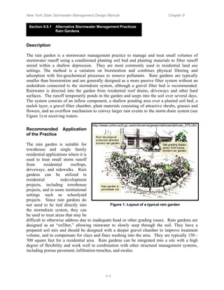
- 1. New York State Stormwater Management Design Manual Chapter 9 Section 9.5.1 Alternative Stormwater Management Practices Rain Gardens Description The rain garden is a stormwater management practice to manage and treat small volumes of stormwater runoff using a conditioned planting soil bed and planting materials to filter runoff stored within a shallow depression. They are most commonly used in residential land use settings. The method is a variation on bioretention and combines physical filtering and adsorption with bio-geochemical processes to remove pollutants. Rain gardens are typically smaller than bioretention and are generally designed as a more passive filter system without an underdrain connected to the stormdrain system, although a gravel filter bed is recommended. Rainwater is directed into the garden from residential roof drains, driveways and other hard surfaces. The runoff temporarily ponds in the garden and seeps into the soil over several days. The system consists of an inflow component, a shallow ponding area over a planted soil bed, a mulch layer, a gravel filter chamber, plant materials consisting of attractive shrubs, grasses and flowers, and an overflow mechanism to convey larger rain events to the storm drain system (see Figure 1) or receiving waters. http://www.cmhc-schl.gc.ca/en/burema/gesein/abhose/abhose_075.cfm Recommended Application of the Practice The rain garden is suitable for townhouse and single family residential applications where it is used to treat small storm runoff from residential rooftops, driveways, and sidewalks. Rain gardens can be utilized in residential redevelopment projects, including townhouse projects, and in some institutional settings such as schoolyard projects. Since rain gardens do not need to be tied directly into Figure 1: Layout of a typical rain garden the stormdrain system, they can be used to treat areas that may be difficult to otherwise address due to inadequate head or other grading issues. Rain gardens are designed as an “exfilter,” allowing rainwater to slowly seep through the soil. They have a prepared soil mix and should be designed with a deeper gravel chamber to improve treatment volume, and to compensate for clays and fines washing into the area. They are typically 150 - 300 square feet for a residential area. Rain gardens can be integrated into a site with a high degree of flexibility and work well in combination with other structural management systems, including porous pavement, infiltration trenches, and swales. 9-9
- 2. New York State Stormwater Management Design Manual Chapter 9 Benefits Rain gardens can have many benefits when applied to redevelopment and infill projects in urban settings. The most notable include: • Effective pollutant treatment for residential rooftops and driveways, including solids, metals, nutrients and hydrocarbons • Groundwater recharge augmentation • Micro-scale habitat • Aesthetic improvement to turfgrass or otherwise hard urban surfaces (Figure 2) • Ease of maintenance, coupling routine landscaping maintenance with effective stormwater management control • Promotion of watershed education and stewardship http://www.urbanwaterquality.org/RainGardens/rgindex1.htm Figure 2: Rain gardens also have aesthetic value. Feasibility/Limitations Rain gardens have some limitations, similar to bioretention, that restrict their application. The most notable of these include: • Steep slopes. Rain gardens require relatively flat slopes to be able to accommodate runoff filtering through the system. Some design modifications can address this 9-10
- 3. New York State Stormwater Management Design Manual Chapter 9 constraint through the use of berms and timber or block retaining walls on moderate slopes. • Compacted and clay soils. Soils compacted by construction and heavy clay soils need more augmentation than sandy soils, though all soils should be prepared to specification. In compacted soils and clay, additional excavation is necessary, along with a gravel bed and, under some circumstances, an underdrain system. • A single rain garden system should be designed to receive sheet flow runoff or shallow concentrated flow from an impervious area or from a roof drain downspout with a drainage area equal to or less than 1,000 square feet. Because the system works by filtration through a planting media, runoff must enter at the surface. • The rain garden must be sited in a location that allows overflow from the area to sheet flow or be otherwise safely conveyed to the formal drainage system. Rain gardens should be located downgradient and at least 10 feet from basement foundations. • Rain gardens require a modest land area to effectively capture and treat residential runoff from storms up to approximately the 1-inch precipitation event. • Rain gardens should not be located in areas with heavy tree cover, as the root systems will make installation difficult and may be damaged by the excavation. Sizing and Design Guidance Stormwater quantity reduction in rain gardens occurs via evaporation, transpiration, and infiltration, though only the infiltration capacity of the soil and drainage system is considered for water quality sizing. The storage volume of a rain garden is achieved within the gravel bed, soil medium and ponding area above the bed. The size should be determined using the water quality volume (WQv), where the site area is the impervious area draining to the rain garden. The following sizing criteria should be followed to arrive at the surface area of the rain garden, based on the required WQv: WQv ≤ VSM + VDL + (DP x ARG) VSM = ARG x DSM x nSM VDL (optional) = ARG x DDL x nDL where: VSM = volume of the soil media [cubic feet] VDL = volume of the drainage layer [cubic feet] ARG = rain garden surface area [square feet] DSM = depth of the soil media, typically 1.0 to 1.5 feet [feet] DDL = depth of the drainage layer, typically .05 to 1.0 feet [feet] DP = depth of ponding above surface, maximum 0.5 feet [feet] 9-11
- 4. New York State Stormwater Management Design Manual Chapter 9 nSM = porosity of the soil media (≥20%) nDL = porosity of the drainage layer (≥40%) WQv = Water Quality Volume [cubic feet], as defined in Chapter 4 of the New York Stormwater Management Design Manual A simple example for sizing rain gardens based upon WQv is presented in Table 1. Table 1: Rain Garden Simple Sizing Example Given a 1,000 square foot impervious drainage area (e.g., rooftop), a rain garden design has been proposed with a 200 square foot surface area, a soil layer depth of 12 inches, a drainage layer depth of 6 inches, and an allowable ponding depth of 3 inches. Evaluate if the proposed rain garden design satisfies site WQv requirements Step 1: Calculate water quality volume using the following equation: (P) (Rv) (A) WQv = 12 where: P = 90% rainfall number = 0.9 in Rv = 0.05+0.009 (I) = 0.05+0.009(100) = 0.95 I = Percentage impervious area draining to site = 100% A = Area draining to practice (treatment area) = 1,000 ft2 (0.9)(0.95)(1,000) WQv = WQv = 71.25 ft3 12 Step 2: Solve for drainage layer and soil media storage volume: VSM = ARG x DSM x PSM VDL = ARG x DDL x PDL where: ARG = proposed rain garden surface area = 200 ft2 DSM = depth soil media = 12 inches = 1.0 ft DDL = depth drainage layer = 6 inches = 0.5 ft PSM = porosity of soil media = 0.20 PDL = porosity of drainage layer = 0.40 VSM = 200 ft2 x 1.0 ft x 0.20 = 40 ft3 VDL = 200 ft2 x 0.5 ft x 0.40 = 40 ft3 DP = ponding depth = 3 inches = 0.25 ft WQv ≤ VSM+VDL+(DP x ARG) = 40 ft3 + 40 ft3 + (0.25 ft x 200 ft2) WQv = 71.25 ft3 ≤ 130.0 ft3, OK Therefore, the proposed design for treating an area of 1,000 ft2 satisfies the WQv requirements . 9-12
- 5. New York State Stormwater Management Design Manual Chapter 9 Siting Rain gardens should be located within approximately 30 feet of the downspout or impervious area treated. Rooftop conveyance to the rain garden is through roof leaders directed to the area, with stone or splash blocks placed at the point of discharge into the rain garden to prevent erosion. Runoff from driveways and other paved surfaces should be directed to the rain garden at a non-erosive rate through shallow swales, or allowed to sheet http://www.metrocouncil.org/directions/water/ flow across short distances (Figure 3). MEPgrantsOct03.htm Figure 3: This rain garden treats road and Sizing The following considerations should be driveway runoff. given to design of the rain garden (after PA Stormwater Design Manual, Bannerman 2003 and LID Center): • Ponding depth above the rain garden bed should not exceed 6 inches. The recommended maximum ponding depth of 6 inches provides surface storage of stormwater runoff, but is not too deep to affect plant health, safety, or create an environment of stagnant conditions. On perfectly flat sites, this depth is achieved through excavation of the rain garden and backfilling to the appropriate level; on sloping sites, this depth can be achieved with the use of a berm on the downslope edge, and excavation/backfill to the required level. • Surface area is dependent upon storage volume requirements but should not exceed a maximum loading ratio of 5:1 (drainage area to infiltration area, where drainage area is assumed to be 100% impervious; to the extent that the drainage area is not 100% impervious, the loading ratio may be modified) • A length to width ratio of 2:1, with the long axis perpendicular to the slope and flow path is recommended. Soil The composition of the soil media should consist of 50% sand, 20-30% topsoil with less than 5% clay content, and 20-30% leaf compost. The depth of the amended soil should be approximately 4 inches below the bottom of the deepest root ball. Construction Rain gardens should initially be dug out to a 24” depth, then backfilled with a 6 - 10 inch layer of clean washed gravel (approximately 1.5-2.0 inch diameter rock), and filled back to the rain garden bed depth with a certified soil mix. Environmental/Landscaping Elements The rain garden system relies on a successful native plant community to stabilize the ponding area, promote infiltration, and uptake pollutants (Figure 2). To do that, plant species need to be selected that are adaptable to the wet/dry conditions that will be present. The goal of planting the 9-13
- 6. New York State Stormwater Management Design Manual Chapter 9 rain garden is to establish an attractive planting bed with a mix of upland and wetland native shrubs, grasses and herbaceous plant material arranged in a natural configuration starting from the more upland species at the outer most zone of the system to more wetland species at the inner most zone. Plants should be container grown with a well established root system, planted on one foot centers. Table 2 provides a representative list of possible plant selections. Rain gardens should not be seeded as this takes too long to establish the desired root system, and seed may be floated out with rain events. The same limitation is true for plugs. Shredded hardwood mulch should be applied up to 2” to help keep soil in place. Table 2: Suggested Plant List Shrubs Herbaceous Plants Witch Hazel Cinnamon Fern Hamemelis virginiana Osmunda cinnamomea Winterberry Cutleaf Coneflower Ilex verticillata Rudbeckia laciniata Arrowwood Woolgrass Viburnum dentatum Scirpus cyperinus Brook-side Alder New England Aster Alnus serrulata Aster novae-angliae Red-Osier Dogwood Fox Sedge Cornus stolonifera Carex vulpinoidea Sweet Pepperbush Spotted Joe-Pye Weed Clethra alnifolia Eupatorium maculatum Switch Grass Panicum virgatum Great Blue Lobelia Lobelia siphatica Wild Bergamot Monarda fistulosa Red Milkweed Asclepias incarnata Adapted from NYSDM Bioretention Specifications, Bannerman, Brooklyn Botanic Garden. Maintenance Rain gardens are intended to be relatively low maintenance. Weeding and watering are essential the first year, and can be minimized with the use of a weed free mulch layer. Rain gardens should be treated as a component of the landscaping, with routine maintenance provided by the homeowner or homeowners’ association, including the occasional replacement of plants, mulching, weeding and thinning to maintain the desired appearance. Homeowners and 9-14
- 7. New York State Stormwater Management Design Manual Chapter 9 landscapers should be educated regarding the purpose of the rain garden, so the desirable aspects of ponded water are recognized and maintained. Cost The cost of a rain garden is typically $10-$12 dollars per square foot of surface area (Bannerman 2003). References Bannerman, Roger. 2003. Rain Gardens, A How-to Manual for Homeowners. University of Wisconsin. PUB-WT-776. Brooklyn Botanic Garden. 2004.Using Spectacular Wetland Plantings to Reduce Runoff. Low Impact Development Center, Inc. (LID) http://www.lid-stormwater.net/intro/sitemap.htm#permpavers Pennsylvania Stormwater Best Management Practices Manual. Draft 2005. 9-15
- 8. New York State Stormwater Management Design Manual Chapter 9 Section 9.5.2 Alternative Stormwater Management Practices Cisterns Description Cisterns capture and store stormwater runoff to be used later for irrigation systems or filtered and reused for household activities such as toilet flushing and clothes washing. Cisterns can be constructed of any water-retaining material and their size can vary from hundreds of gallons for residential uses to tens of thousands of gallons for commercial and/or industrial uses. They can be located either above or below ground and can be constructed on-site or pre-manufactured. The basic components of a cistern include: a secure cover, a leaf/mosquito screen, a coarse inlet filter with clean-out valve, an overflow pipe, a manhole or access hatch, a drain for cleaning, and an extraction system (tap or pump). Additional features might include a water level indicator, a sediment trap, or an additional tank for extra storage volume. Recommended Application of the Practice Cisterns can be used in most areas (residential, commercial, and industrial; Figure 1) due to their minimal site constraints relative to other stormwater management practices. They can be applied to manage almost every land use type from very dense urban to more rural residential areas. The sizes of cisterns are directly proportional to their contributing drainage areas and intended use. http://www.lid-stormwater.net/raincist/raincist_benefits.htm Figure 1: Cisterns can be designed for smaller residential uses (left) or for large business operations (right). 9-16
- 9. New York State Stormwater Management Design Manual Chapter 9 Benefits Cisterns provide many stormwater management benefits, among them: • Cisterns can reduce stormwater runoff volumes, and delay and reduce peak runoff flow rates. • Stored water from cisterns can help reduce water consumption, which ultimately reduces the demand on municipal water systems. Water from cisterns, if managed correctly, can be used for drinking, bathing, and cooking as well as for garden irrigation (Kessner, 2000). • Cisterns can also be used in urban redevelopment scenarios to reduce runoff volumes in areas where soils are compacted, groundwater levels are high or hot-spot conditions exist that preclude infiltration. Feasibility/Limitations The biggest limitation to the installation and use of cisterns to capture and reuse stormwater is the need for active management/maintenance and initial capital cost. Generally, the ease and efficiency of municipal water supply systems and the low cost of water prevent people from implementing on-site water conservation and reuse systems. Specific limitations include: • Cisterns require periodic maintenance and cleaning to ensure effective stormwater treatment. If water from a cistern is intended for household use, adequate design and maintenance on the part of the homeowner are necessary to ensure all water is appropriately treated before use. • A supplementary water source may be needed if water captured in a cistern does not fulfill the intended water demand. Alternatively if captured water is not used as anticipated, the extra water entering the cistern will need to be managed to prevent overtopping. • To achieve significant community wide acceptance, an active community education program and a high profile public site demonstration will likely be necessary. • In cold climates specific design or maintenance strategies will need to be considered to prevent freezing such as providing insulation or disconnecting the system. Sizing and Design Guidance Depending on the intended use, cistern sizing is a function of the impervious area that drains to the device and the amount of water required for the reuse activity (e.g., laundry or toilet flushing). The basic equation for sizing a cistern based on the contributing area is as follows: 9-17
- 10. New York State Stormwater Management Design Manual Chapter 9 Vol = WQv * 7.5 gals/ft3 where: Vol = Volume of cistern [gallons] WQv = Water Quality Volume [cubic feet], as defined in Chapter 4 of the New York Stormwater Management Design Manual 7.5 = Conversion factor [gallons per cubic foot] A simple example for sizing cisterns using WQv is presented in Table 1. Table 1: Simple Cistern Sizing Example Given a 3,000 square foot impervious surface area draining to a cistern, calculate the water quality volume and required cistern volume. Step 1: Calculate water quality volume using the following equation: (P)(Rv)(A) WQv = 12 where: P = 90% rainfall number = 0.9 in Rv = 0.05+0.009 (I) = 0.05+0.009(100) = 0.95 I = the percentage of impervious area draining to site = 100% A = the Area Draining to Practice = 3,000 ft2 (0.9)(0.95)(3,000) WQv = WQv = 213.75 ft3 12 Step 2: Calculate cistern volume using equation above: Vol = (WQv) (7.5 gals/ft3) Vol = WQv x 7.5 gals/ft3 Vol = 1603 gal Therefore, to treat the water quality volume for the area draining to the practice, a 1,650-gallon cistern is required. Siting A cistern can be located beneath a single downspout or one large cistern can be located such that it collects stormwater from several sources. Due to the size of rooftops and the amount of contributing impervious area, increased runoff volume and peak discharge rates for commercial and industrial sites may require large capacity cisterns. Cisterns designed to capture small, frequent storm events need to be either actively or passively drained to provide storage for subsequent storm events or located in an area where overflow runoff can be conveyed to a suitable area such as open yard, swale, a rain garden or the storm drain system. In cold climates where cisterns are designed for use throughout the year, cisterns placed on the ground require extra insulation on the exposed surfaces (Stensrod, et al., 1989). For cisterns placed on rock, the bottom surface will also need to be insulated. For underground systems it may be cost-prohibitive to place the cistern below the freezing depth, so alternatively, insulation 9-18
- 11. New York State Stormwater Management Design Manual Chapter 9 can be placed below the surface and above the underground cistern to prevent freezing. Other methods to prevent freezing include lining the intake pipe and cistern with heat tape and closing the overflow valve (Stensrod, et al., 1989). Water levels should also be lowered at the beginning of winter to prevent possible winter damage and provide needed storage for spring snow melt. Environmental/Landscaping An effort should be made to meet property owners’ preferences in providing attractive above ground cisterns. The likelihood of continued use of the cistern is increased if they are an attractive part of the landscape (Figure 3). Landscaping should be used to shade cisterns to reduce algae growth and to provide visual screening. Maintenance Maintenance requirements for cisterns vary depending on if the water will be used domestically or only for irrigation. Depending on the design and use of the cistern, winterization maintenance may also be necessary. Generally, cisterns inspections should be conducted semi-annually and the following components inspected and either repaired or replaced as needed: • Roof catchments should be inspected to ensure that no particulate matter or other parts of the roof are entering the gutter and http://www.terrain.org/essays/16/calhoun.htm downspout to the cistern. Figure 3: Cisterns can be incorporated into the overall landscaping of the site. • Gutters and downspouts should be inspected to ensure that no leaks or obstructions are occurring. • Roof washers, cleanout plugs, screens, covers, and overflow pipes should be inspected and replaced as needed. • Inspections should also include inflow and outflow pipes as well as any accessories, such as sediment traps. Cost The cost for cisterns can vary greatly depending on its size, material and location (above or below ground). Costs range from a low of about $0.50 per gallon for large fiberglass tanks to up to $4.00 per gallon for welded steel tanks (TWDB, 2005). The following are representative costs for pre-manufactured cisterns, not including labor and accessory costs (Table 2). 9-19
- 12. New York State Stormwater Management Design Manual Chapter 9 Table 2: Cost Guide – Pre-manufactured Cisterns (LID Center) Material Cost (small system) Cost (large system) Galvanized Steel $225 for 200 gallons $950 for 2,000 gallons Polyethylene $160 for 165 gallons $1,100 for 1,800 gallons Fiberglass $660 for 350 gallons $10,000 for 10,000 gallons Fiberglass/Steel Composite $300 for 300 gallons $10,000 for 5,000 gallons References Kessner, K., 2000. How to Build a Rainwater Catchment Cistern. The March Hare, Summer 2000, Issue 25, http://www.dancingrabbit.org/building/cistern.html Low Impact Development Center, Inc. (LID). Accessed 2005. http://www.lid-stormwater.net/intro/sitemap.htm Stensrod, O. and Gosback, J. September 1978. translated May 1989, Johansen, J. and Seifert R.. Water Cistern Construction for Small Houses. Alaska Building Research Series, HCM-01557. Texas Water Development Board (TWDB). 2005. The Texas Manual on Rainwater Harvesting 3rd Edition. http://www.twdb.state.tx.us/publications/reports/RainwaterHarvestingManual_3rdedition.pdf The Urban Garden Center (UGC) http://www.urbangardencenter.com/products/rainbarrel/index.html 9-20
- 13. New York State Stormwater Management Design Manual Chapter 9 Section 9.5.3 Alternative Stormwater Management Practices Green Roofs Description Green roofs consist of a layer of vegetation and soil installed on top of a conventional flat or sloped roof (Figure 1). The rooftop vegetation captures rainwater allowing evaporation and evapotranspiration processes to reduce the amount of runoff entering downstream systems, effectively reducing stormwater runoff volumes and attenuating peak flows. There are two types of green roof designs, extensive and intensive. Extensive green roofs have a thin soil layer so are lighter, less expensive, and generally require low maintenance. Intensive green roofs often have pedestrian access and are characterized by a deeper soil layer with greater weight, higher capital cost, increased plant diversity, and more maintenance requirements. The general components of any green roof system include a: • roof structure capable of supporting the weight of a green roof system • waterproofing system designed to protect the building and roof structure; • drainage layer consisting of a porous media capable of water storage for plant uptake http://www.fcwc.org/WEArchive/010203_wbj/rain.htm • a geosynthetic layer to prevent fine soil media from clogging the porous media Figure 1: Green roof installed on a sloped roof • soil with appropriate characteristics to support selected green roof plants • plants with appropriate tolerance for harsh rooftop conditions and shallow rooting depths. Figure 2 is a schematic of the various layers included in a typical green roof system. Recommended Application of Practice Green roofs are suitable for retrofit or redevelopment projects as well as new buildings, and can be installed on small garages or larger industrial, commercial and municipal buildings. Green roofs present an above ground management alternative when the on-site space availability for stormwater practices is limited. Green roofs can be installed on flat roofs or on roofs with slopes up to 30% provided special strapping and erosion control devices are used (Peck and Kuhn, 2003). Generally, extensive green roofs can be built on flat or sloped roofs; where as intensive systems are built on flat or tiered roofs. 9-21
- 14. New York State Stormwater Management Design Manual Chapter 9 Green roofs are most effective in reducing runoff volume and rates for land uses with high percentages of rooftop coverage such as commercial, industrial and multifamily housing (Stephens et al., 2002). Green roofs on lots with approximately 70% impervious area have been shown to retain as much as 80% of the total annual runoff in regions with low total annual rainfall and 30% in areas with high total annual rainfall (Stephens et al., 2002), which likely http://www.uwm.edu/Dept/GLWI/ecoli/Greenroof/images/ greenroofcom.jpg brackets the range of performance likely to be observed in New York State. Figure 2: Green roof layers Benefits Green roofs reduce runoff volumes and delay peak flows while providing a number of other benefits to the urban environment, private building owners, and the public. The most notable include: • Green roofs help achieve stormwater management goals by reducing total annual runoff volumes (Roofscapes, Inc., 2005). • The layers of soil and vegetation on the rooftop moderate interior building temperatures, and provide insulation from the heat and cold. As a result the amount of energy required to heat and cool the building is reduced, providing energy savings to the owner. The increased insulation reduces HVAC infrastructure requirements, and therefore building construction costs. • The additional rooftop insulation protects rooftop materials from ultraviolet radiation and extreme temperature fluctuations, which deteriorates standard roofing materials. It is estimated that green roofs can extend the life of a roof by as long as 20 years (Velazquez, 2005). • Green roofs can also be designed to insulate the building interior from outside noise, and sound-absorbing properties of green roof infrastructure can make surrounding areas quieter. • Fully saturated green roofs can provide fire resistance and inhibit the spread of fire from adjacent buildings. • Green roofs reduce the urban heat island effect by cooling and humidifying the surrounding air. 9-22
- 15. New York State Stormwater Management Design Manual Chapter 9 • Green roofs help filter and bind airborne dust and other particulates, improving air quality (Barr Engineering Company, 2003). • The additional rooftop vegetation within an urban or suburban environment creates habitat for birds and butterflies. • With thoughtful design, green roofs can be aesthetically pleasing and improve views from neighboring buildings as illustrated in Figure 3, with a high-rise residential building in Manhattan. • A benefit specific to extensive green roofs is pedestrian access to a scenic space within an urban environment (Figure 4). Photo courtesy of Cesar Pelli & Associates Figure 3: A green roof installed on an Figure 4: Extensive roofs increase apartment building in Manhattan along aesthetics in the urban environment. the Hudson River. Feasibility/Limitations The primary limitation to the implementation of green roofs is increased design and construction costs. Green roof designs need to include any structural requirements necessary to support the additional weight of soil, vegetation, and possibly pedestrians. For retrofit projects, a licensed structural engineer or architect must conduct a structural analysis of the existing structure, which will dictate the type of green rooftop system and any necessary structural reinforcement. Other limitations include: • Damage to or failure of waterproofing elements present a risk of causing water damage. However, similar to traditional roof installations, a warranty can help guarantee that any damage to the water proofing system will be repaired. 9-23
- 16. New York State Stormwater Management Design Manual Chapter 9 • Extreme weather conditions can impact plant survival. • Green roof maintenance is higher than for traditional roofs. • The need to provide safe access to the rooftop for construction and maintenance. • Supplemental irrigation during the first year may be necessary to establish vegetation, and a long-term supplemental irrigation system may be required for some intensive systems. • In cold climates, snow loads need to be accounted for when determining the structural capacity required to install a green roof system. • In many building designs it will likely be more feasible to incorporate an extensive green roof design versus an intensive system. Sizing and Design Guidance Green roofs can be counted as pervious area that can be applied towards meeting the total impervious cover reduction target for redevelopment sites that can be accepted as a deviation from the technical standards. Simple sizing calculations can also be made to check the actual storage volume provided by a proposed green roof design. The following sizing guidelines are based upon providing a stormwater treatment volume equal to the New York Unified Stormwater Sizing Criteria for water quality volume. Stormwater treatment in green roofs occurs via evaporation, transpiration, and filtration. A simplified (and conservative) approach to estimating the volume of water that can be effectively managed and treated by a green roof system is outlined below and based on an instantaneous volume that can be stored in the soil media, drainage layer, and surface ponding area together. WQv ≤ VSM + VDL + (DP x AGR) VSM = AGR x DSM x nSM VDL = AGR x DDL x nDL where: VSM = volume of the soil media [cubic feet] VDL = volume of the drainage layer [cubic feet] AGR = green roof surface area [square feet] DSM = depth of the soil media [feet] DDL = depth of the drainage layer [feet] DP = depth of ponding above surface [feet] nSM = porosity of the soil media (~20%) nDL = porosity of the drainage layer (~25%) WQv = Water Quality Volume [cubic feet], as defined in Chapter 4 of the New York Stormwater Management Design Manual 9-24
- 17. New York State Stormwater Management Design Manual Chapter 9 A simple example for sizing green roofs based on WQv is presented in Table 1. Table 1: Simple Green Roof Sizing Example A green roof has been designed for a 1,100 square foot rooftop. The proposed system has a 900 square foot surface area, a 3 inch soil media layer, and a 2 inch drainage layer. Given the proposed design, evaluate if the proposed green roof design satisfies site WQv requirements: Step 1: Calculate water quality volume using the following equation: (P)(Rv)(A) WQv = 12 where: P = 90% rainfall number = 0.9 in Rv = 0.05+0.009 (I) = 0.05+0.009(100) = 0.95 I = the percentage of impervious area draining to site = 100% A = area draining to practice = 1,100 ft2 (0.9)(0.95)(1,100) WQv = 12 WQv = 78.4 ft3 Step 2: Calculate the drainage layer and soil media storage volume: VSM = AGR x DSM x PSM VDL = AGR x DDL x PDL where: AGR = green roof surface area = 900 ft2 DSM = depth soil media = 3 inches = 0.25 ft DDL = depth drainage layer = 2 inches = 0.17 ft PSM = porosity of soil media = 0.20 PDL = porosity of drainage layer = 0.25 VSM = 900 ft2 x 0.25 ft x 0.20 = 45.0 ft3 VDL = 900 ft2 x 0.17 ft x 0.25 = 38.25 ft3 DP = ponding depth = 0.5 inches = 0.04 ft WQv ≤VSM+VDL+(DP x AGR) = 45.0 ft3 + 38.25 ft3 + (0.04 ft x 900 ft2) WQv = 78.4 ft3 ≤ 119.25 ft3, OK Therefore, the proposed design satisfies the WQv requirements. Each green roof project is unique, given the purpose of the building, its architecture and the preferences of its owner and end user. However, several key design features should be kept in mind during the design, of any green rooftop systems. 9-25
- 18. New York State Stormwater Management Design Manual Chapter 9 Extensive systems are characterized by low weight, lower capital cost, and minimal plant diversity (Figure 5). The growing medium is usually a mixture of sand, gravel, crushed brick, peat, or organic matter combined with soil. The soil media ranges between two and six inches in depth and increases the roof load by 16 to 35 pounds per square foot when fully saturated. Since the growing medium is shallow and the Unterlage, 1997 microclimate is harsh, plant species used in extensive systems should be low and hardy, Figure 5: Extensive Cross-Section which typically involves alpine, arid, or indigenous species. Intensive systems have a deeper soil layer and a corresponding greater weight (Figure 6). The growing medium is often soil based and ranges in depth from eight to 24 inches, with a saturated roof loading of between 60 and 200 pounds per square foot. Designers can use a diverse range of trees, shrubs and groundcover because the deeper growing medium allows longer root systems. This allows the designer to develop a more complex ecosystem. Both a structural engineer and an experienced installer are recommended for design and installation of intensive systems (Magco, 2003). The four principle components of any green roof system are the roof structure, waterproofing, drainage system, and soil media. General design guidelines for each of these components are described below. Roof Structure The load bearing capacity of the roof structure is critical for the support of soil, plants, and any people who will be accessing the green roof (for either maintenance or recreation). Generally, green roofs weighing more than 17 pounds per square foot saturated require consultation with a structural engineer (Barr Engineering, 2003). As a fire resistance measure, non-vegetative materials, such as stone or pavers should be installed around all rooftop openings and at the base of all walls that contain openings (Barr Engineering, 2003). On sloped roofs additional erosion control measures, such as cross-battens, may be necessary to stabilize drainage layers. Waterproofing In a green roof system the first layer Unterlage, 1997 above the roof surface is a waterproofing membrane. Two common waterproofing techniques used for the Figure 6: Intensive Cross-Section construction of green roofs are monolithic and 9-26
- 19. New York State Stormwater Management Design Manual Chapter 9 thermoplastic sheet membranes. An additional protective layer is generally placed on top of either of these membranes followed by a physical or chemical root barrier. Once the waterproofing system has been installed it should be fully tested prior to construction of the drainage system. Drainage System The drainage system includes a porous drainage layer and a geosynthetic filter mat to prevent fine soil particles from clogging the porous media. The drainage layer can be made up of gravels or recycled-polyethlylene materials that are capable of water retention and efficient drainage. The depth of the drainage layer depends on the load bearing capacity of the roof structure and the stormwater retention requirements. Once the porous media is saturated excess water should be directed to a traditional rooftop storm drain system. The porosity of the drainage system should be greater than or equal to 25% (Cahill Associates, 2005). Soil The soil layer above the drainage system is the growing media for the plants in a green roof system. Soils used in green roofs are generally lighter than standard soil mixes, and consist of 75% mineral and 25% organic material (Barr Engineering, 2003), and no clay size particles. The chemical characteristics of the soil (e.g., pH, nutrients, etc.) should be carefully selected in consideration with the planting plan. The porosity of the soil layer, measured as non-capillary pore space at field capacity, should be greater than or equal to 15% (Cahill Associates, 2005). Environmental/Landscape Elements Plant selection for green rooftops is an integral design consideration, which is governed by local climate and design objectives. A qualified botanist or landscape architect should be consulted when choosing plant material. For extensive systems, plant material should be confined to hardier or indigenous varieties of grass and sedum. Root size and depth should also be considered to ensure that the plants stabilize the shallow depth of soil media. Plant choices can be much more diverse for intensive systems. The location of the roof plays an important role in the design process. The height of the roof, its exposure to wind, snow loading potential, its orientation to the sun and shading by surrounding buildings all have an impact on the selection of appropriate vegetation. It is estimated that approximately 5 years is required for a green roof to reach its optimum performance (Cahill Associates, 2005 - Draft Pennsylvania Stormwater Management Manual). Maintenance Green roof maintenance may include watering, fertilizing and weeding, and is typically greatest in the first two years as plants become established. Maintenance largely depends on the type of green roof system installed and the type of vegetation planted. Maintenance requirements in intensive systems are generally more costly and continuous, compared to extensive systems. The use of native vegetation is recommended to reduce plant maintenance in both extensive and intensive systems. A green roof should be monitored after completion for plant establishment, leaks and other functional or structural concerns. Vegetation should be monitored for establishment and viability, particularly in the first two years. Irrigation and fertilization is typically only a 9-27
- 20. New York State Stormwater Management Design Manual Chapter 9 consideration during the first year before plants are established. After the first year, maintenance consists of two visits a year for weeding of invasive species, and safety and membrane inspections (Magco, 2003). Cost Green roof costs are variable and have been estimated at $5.00 to $12.00 per square foot for a new green roof and $7.00 to $20.00 per square foot for a retrofit (Liptan and Strecker, 2003). Operation and maintenance costs for extensive systems are estimated to be between $1.00 to $1.60 per square foot for the first two years, and for intensive systems $1.00 to $1.60 per square foot annually (Canadian currency converted to U.S. from Peck and Kuhn, 2003). Design costs typically run five to ten percent of the total project cost and administration and site review costs are two and a half to five percent of the total project cost (Peck and Kuhn, 2003). Irrigation systems in intensive systems typically cost between $1.60 and $3.20 per square foot (Canadian currency converted to U.S. from Peck and Kuhn, 2003). References/Further Resources Barr Engineering Company. 2003. Minnesota Urban Small Sites BMP Manual: Stormwater Best Management Practices for Cold Climates. Metropolitan Council Environmental Services. St. Paul, Minnesota. http://www.metrocouncil.org/environment/Watershed/bmp/manual.htm Cahill Associates, Inc. January 2005. Draft Pennsylvania Stormwater Best Management Practices Manual, Department of Environmental Protection, Bureau of Stormwater Management, and Division of Waterways, Wetlands, and Erosion Control. City of Chicago. Accessed 2005. Guide to Rooftop Gardening http://egov.cityofchicago.org/webportal/COCWebPortal/COC_ATTACH/GuidetoRooftopGardening_v2.pdf City of Portland. 2000. Stormwater Management Manual. City of Portland. Portland, Oregon. Flinker, P., 2005. Rhode Island Urban Environmental Design Manual “Green Rooftop Systems” Narrative. Sustainable Watersheds Office Rhode Island Department of Environmental Management. http://www.dem.ri.gov/programs/bpoladm/suswshed/pubs.htm Liptan, T. and E. Strecker. 2003. Ecoroofs – A More Sustainable Infrastructure. Presented at Urban Stormwater: Enhancing Programs at the Local Level. February 17-20, 2003. Co- sponsored by US EPA, Chicago Botanic Gardens and Conservation Technology Information Center. Chicago, Illinois. Magco, Inc. Accessed 2003. Intensive and Extensive Green Roofs. http://www.magco.com/extensive_intensive.html Maryland Department of the Environment. Green Roof - Fact Sheet. Maryland's Stormwater Management Manual. http://www.mde.state.md.us/assets/document/sedimentStormwater/SWM_greenroof.pdf 9-28
- 21. New York State Stormwater Management Design Manual Chapter 9 Peck, S. and M. Kuhn. Accessed 2003. Design Guidelines for Green Roofs. http://www.cmhc-schl.gc.ca/en/imquaf/himu/himu_002.cfm Roofscapes, Inc. Accessed 2005. Green Technology for the Urban Environment. www.roofmeadow.com. Snodgrass, E.. Accessed 2003. http://www.greenroofplants.com/ Stephens, K. A., Graham, P. and D. Reid. 2002. Stormwater Planning: A Guidebook for British Columbia. British Columbia Ministry of Water, Land and Air Protection. The Cardinal Group, Inc. Accessed 2002. www.greenroofs.ca. Velazquez, L. S. 2005. Greenroofs.com. http://www.greenroofs.com 9-29
- 22. New York State Stormwater Management Design Manual Chapter 9 Section 9.5.4 Alternative Stormwater Management Practices Stormwater Planters Description Stormwater planters are small landscaped stormwater treatment devices that can be placed above or below ground and can be designed as infiltration or filtering practices. Stormwater planters use soil infiltration and biogeochemical processes to decrease stormwater quantity and improve water quality, similar to rain gardens and green roofs. Three versions of stormwater planters include contained planters, infiltration planters, and flow-through planters. Contained planters are essentially potted plants placed above impervious surfaces (Figure 1). Stormwater infiltrates through the soil media within the container, and overflows when the void space or infiltration capacity of the container is exceeded. Infiltration planters are contained planters with a pervious bottom that allows stormwater to infiltrate through the soil media within the planter and pass into the underlying soil matrix (Figure 2). Flow-through planters are contained planters with an under drain system that conducts filtered stormwater to the storm drain system or downstream waterway (Figure 3). All three types of stormwater planters include three common elements: planter “box” material (e.g., wood or concrete); growing medium consisting of organic soil media; and vegetation. Infiltration and flow-through planters may also include splash rock, filter fabric, gravel drainage layer, and perforated pipe. Portland, OR, 2004 Figure 1: Contained stormwater planter 9-30
- 23. New York State Stormwater Management Design Manual Chapter 9 Portland, OR, 2004 Figure 2: Infiltration stormwater planter Portland, OR, 2004 Figure 3: Flow-through stormwater planter 9-31
- 24. New York State Stormwater Management Design Manual Chapter 9 Recommended Application of the Practice The versatility of stormwater planters makes them uniquely suited for urban redevelopment sites. Depending on the type, they can be placed adjacent to buildings, on terraces or rooftops. Building downspouts can be placed directly into infiltration or flow-through planters; where as contained planters are designed to capture rainwater, essentially decreasing the site impervious area. The infiltration and adsorption properties of stormwater planters make them well suited to treat common pollutants found in rooftop runoff, such as nutrients, sediment and dust, and bacteria found in bird feces. Stormwater planters are most effective at treating small storm events because of their comparatively small individual treatment capacity. Benefits Stormwater planters provide many stormwater management benefits, among them: • If on-site soils or a high seasonal groundwater table are not suitable for infiltration practices (e.g. rain garden or infiltration trench), flow-through or contained stormwater planters make filtration treatment possible. • Reduction of stormwater volumes and velocities discharging from treated impervious areas. • Flow-through or contained planters do not require a setback from a building foundation, though appropriate waterproofing technology should be incorporated into the design. • Creates an aesthetic landscape element, as well as providing micro-habitat within an urban environment. Feasibility/Limitations The primary limitation to the use of stormwater planters is their size. They are by definition small-scale stormwater treatment cells that are not well suited to treat runoff from large storm events, or large surface areas. They can however be used in series or to augment other stormwater management practices. Other limitations include: • Stormwater planters are not designed to treat runoff from roadways or parking lots and are ideally suited for treating rooftop or courtyard/plaza runoff. Flow-through and infiltration stormwater planters should not receive drainage from impervious areas greater than 15,000 square feet. • For all three types of stormwater planters, if the infiltration capacity of the soil is exceeded, the planter will overflow. Excess stormwater needs to be directed to a secondary treatment system or released untreated to the storm drain system. 9-32
- 25. New York State Stormwater Management Design Manual Chapter 9 Sizing and Design Guidance Stormwater planters should initially be sized to satisfy the WQv requirements for the impervious surface area draining to the practice. This does not apply to contained planters because they are designed to decrease impervious area, not receive additional runoff from adjacent surfaces. The basis for the sizing guidance is the same as that for bioretention (see Chapter 6 of the New York Stormwater Management Design Manual) and relies on the principles of Darcy’s Law, where water is passed through porous media with a given head, a given hydraulic conductivity, over a given timeframe (Flinker, 2005). The equation for sizing an infiltration or flow-through stormwater planter based upon the contributing area is as follows: Af = WQv x (df)/ [k x (hf + df)(tf)] where: Af = the required surface area [square feet] Vol = the treatment volume [cubic feet] df = depth of the soil medium [feet] k = the hydraulic conductivity [in ft/day, usually set at 4 ft/day, but can be varied depending on the properties of the soil media] hf = average height of water above the planter bed [maximum 12 inches] tf = the design time to filter the treatment volume through the filter media [usually set at 3 to 4 hours] WQv = water quality volume [cubic feet], as defined in Chapter 4 of the New York Stormwater Management Design Manual A simple example for sizing a stormwater planter using WQv is presented in Table 1. The ultimate size of a stormwater planter is a function of either the impervious area or the infiltration capacity of the media. Table 1: Flow-through Stormwater Planter Simple Sizing Example Determine the required surface area of a stormwater planter that will be installed to treat stormwater runoff from an impervious area of 3,000 square feet, given the depth of the soil medium is 1.5 feet. Step 1: Calculate the WQv (P) (Rv) (A) WQv = 12 where: P = 90% rainfall number = 0.9 in Rv = 0.05+0.009 (I) = 0.05+0.009(100) = 0.95 I = percentage impervious area draining to site = 100% A = Area draining to practice = 3,000 ft2 (0.9)(0.95)(3,000) WQv = WQv = 213.75 ft3 12 9-33
- 26. New York State Stormwater Management Design Manual Chapter 9 Table 1 (cont.): Flow-through Stormwater Planter Simple Sizing Example Step 2: Calculate required surface area: Af = WQv*(df) / [k*(hf +df)(tf)] where: WQv = 213.75 ft3 df = depth of soil medium = 1.5 ft k = hydraulic conductivity = 4 ft/day hf = height of water above planter bed = 0.5 ft tf = filter time = 0.17 days (213.75)(1.5) Af = Af = 235.75 ft2 [(4)(0.5+1.5)(0.17)] Therefore, a 240 square foot stormwater planter with a soil medium depth of 1.5 feet will be needed to treat stormwater from a 3,000 square foot area. There are a number of sizing, siting, and material specification guidelines that should be consulted during stormwater planter design. Siting Flow-through and infiltration stormwater planters should not receive drainage from impervious areas greater than 15,000 square feet, and for infiltration planters should be located a minimum distance of ten feet from structures. To prevent erosion, splash rocks should be placed below downspouts or where stormwater enters the planter. Sizing Stormwater planters should be designed to pond water for less than 12 hours, with a maximum ponding depth of 12 inches. An overflow control should redirect high flows to the storm drain system or an alternative treatment facility. Generally, flow-though and infiltration planters should have a minimum width of 1.5 and 2.5 feet, respectively. Soil Soil specifications for the stormwater planter growing medium should allow an infiltration rate of 2 inches per hour, and 5 inches an hour for the drainage layer. The growing medium depth for all three stormwater planter types should be at least 18 inches. For infiltration and flow-through planters the drainage layer should have a minimum depth of 12 inches. Specific considerations for the design of infiltration planters are the depth and infiltration rate of the native soil. The infiltration rate of the native soil should be a minimum of 2 inches per hour, and a minimum infiltration depth of 3 feet should be provided between the bottom of the infiltration practice and any impermeable boundaries, such as the seasonal high groundwater level. Infiltration planters should also be designed and constructed with no longitudinal or lateral slope. 9-34
- 27. New York State Stormwater Management Design Manual Chapter 9 Construction Materials suitable for planter wall construction include stone, concrete, brick, clay, plastic, wood, or other durable material (Figure 4). Treated wood may leach toxic chemicals and contaminate stormwater, and should not be used. Flow-through planter walls can be incorporated into a building foundation, with detailed specifications for planter waterproofing (Figure 5). http://www.lcrep.org/fieldguide/examples/containedplanter.htm Figure 4: Contained stormwater planters Figure 5: This flow-through planter made of concrete collects runoff from a parking garage and is incorporated into the structure Environmental/Landscaping In an attempt to replicate the functions of a forested ecosystem, vegetation selected for stormwater planters should be relatively self-sustaining and adaptable. Native plant species are recommended, and fertilizer and pesticide use should be avoided whenever possible. Tree planting is encouraged in and adjacent to infiltration and flow-through planters for the infiltration, habitat and interception benefits they can provide. Maintenance A regular and thorough inspection regime is vital to the proper and efficient function of stormwater planters. Following completion, planters should be inspected after each storm event greater than 0.5 inches, and at least twice in the first six months. Subsequently, inspections should be conducted annually and after storm events equal to or greater than the 1-year storm event. Routine maintenance activities include pruning and replacing dead or dying vegetation, plant thinning, and erosion repair. Cost Stormwater planters are generally considered cost effective stormwater treatment practices. For one redevelopment project where detailed project records exist stormwater planter costs tallied $2.10 per square foot of managed impervious area or approximately $32.70 per square foot of 9-35
- 28. New York State Stormwater Management Design Manual Chapter 9 the practice. For this project, management, design, and permitting costs comprised 25% of the total budget, and construction the remaining 75% (PBES, 2004). The cost of proprietary stormwater planters, or tree box filters, is approximately $24,000 per acre ($0.55 per square foot) of impervious surface. Annual maintenance cost is approximately 2% to 8% of the system cost or in the range of $200 to $2,000 per impervious acre treated (Flinker, 2005). References City of Portland, Oregon. Revised September 2004. Portland Stormwater Management Manual. http://www.portlandonline.com/bes/index.cfm?c=35122 Flinker, P., 2005. Rhode Island Urban Environmental Design Manual “Green Rooftop Systems” Narrative. Sustainable Watersheds Office Rhode Island Department of Environmental Management. http://www.dem.ri.gov/programs/bpoladm/suswshed/pubs.htm Low Impact Development Center, Inc. (LID). Accessed 2005. http://www.lid-stormwater.net/treebox/treeboxfilter_cost.htm Portland Bureau of Environmental Services (PBES). December 2004. Liberty Centre Parking Garage. http://www.portlandonline.com/bes/index.cfm?c=38135 9-36
- 29. New York State Stormwater Management Design Manual Chapter 9 Section 9.5.5 Alternative Stormwater Management Practices Permeable Paving Description Permeable paving is a broadly defined group of pervious types of pavements used for roads, parking, sidewalks, and plaza surfaces. Permeable paving provides an alternative to conventional asphalt and concrete surfaces and are designed to infiltrate rainfall through the surface, thereby reducing stormwater runoff from a site. In addition, permeable paving reduces impacts of impervious cover by augmenting the recharge of groundwater through infiltration, and providing some pollutant uptake in the underlying soils. Due to the potential high risk of clogging the pavement voids and the underlying soils, permeable paving should be limited in its use and should require strict adherence to manufacturer’s specifications for installation and maintenance. The different types of paving can be broken into two basic design variations: porous pavement and permeable pavers. Porous pavement is a permeable asphalt or concrete surface that allows stormwater to quickly infiltrate to an underlying stone reservoir. Runoff then percolates directly into the underlying soil, which recharges groundwater and removes stormwater pollutants. Runoff can also be drained out of the stone reservoir through an underdrain system connected to the stormdrain system. Porous pavement looks similar to conventional pavement, but is formulated with larger aggregate and less fine particles, which leaves void spaces for infiltration. Permeable pavers include concrete grid and grass pavers, interlocking concrete modules, and brick pavers (Figure 1). Often, these designs do not have an underground stone reservoir, but can provide some infiltration and surface detention of stormwater to reduce runoff velocities. Recommended Application of Practice Permeable paving can be used to treat low traffic roads (i.e., a few houses or a small cul- de-sac), single-family residential driveways, overflow parking areas, sidewalks, plazas, and courtyard areas. Good opportunities can be found in larger parking lots, spillover parking areas, schools, municipal facilities, and urban hardscapes. Permeable paving is intended to capture and manage small frequent rainfall events. These events can include as much as 30 – 50% of the annual precipitation (Schueler, 1987). The system Center for Watershed Protection does not readily work for storms greater than Figure 1: Application of Permeable Pavers 1-inch or with high rainfall intensities. The practice can be applied in both redevelopment and new development scenarios. 9-37
- 30. New York State Stormwater Management Design Manual Chapter 9 Benefits Permeable paving can have many benefits when applied to redevelopment and infill projects in urban centers. The most notable benefits include: • Groundwater recharge augmentation • Runoff reduction to ease capacity constraints in storm drain networks • Effective pollutant treatment for solids, metals, nutrients, and hydrocarbons (see pollutant removal performance, Table 1) • Aesthetic improvement to otherwise hard urban surfaces (e.g., interlocking permeable pavers, lattice pavers) Two long-term monitoring studies of porous pavement systems conducted in Rockville, MD, and Prince William, VA, indicated high removal efficiencies for sediments and nutrients (see Table 1). The Rockville study also reported high removals for zinc (99%), lead (98%), and chemical oxygen demand (82%) (Schueler, 1987). Table 1: Estimated Pollutant Removal Performance of Porous Pavement (Porous Asphalt) (EPA, 1999) Pollutant Parameter % Removal Total Phosphorus 65 Total Nitrogen 80 – 85 Total Suspended Solids 82 – 95 Feasibility/Limitations Major limitations to this practice are suitability of the site grades, subsoils, drainage characteristics, and groundwater conditions. Proper site selection is an important criteria in reducing the failure rate of this practice. Areas with high amounts of sediment-laden runoff and high traffic volume are likely causes of system failure. High volume parking lots, particularly parking drive aisles, high dust areas, and areas with heavy equipment traffic, are not recommended for this practice. Ownership and maintenance responsibility should also be considered in determining the potential for success. Soil It is important to confirm that local soils are permeable and can support adequate infiltration, since past grading, filling, disturbance, and compaction can greatly alter the original infiltration qualities. The underlying parent soils should have a minimum infiltration rate of 0.5 inches per hour. To maintain effective pollutant removal in the underlying soils organic matter content in the subsoils is important. Permeable pavers are typically not installed over a gravel chamber, but can be placed on a sand bed to facilitate drainage. Pavers generally provide more surface storage than infiltration 9-38
- 31. New York State Stormwater Management Design Manual Chapter 9 capacity, but have the same limitations in terms of clogging. Permeable paving should generally have a drainage time of at least 24 hours. Cold Climate Considerations Permeable paving practices can be used effectively in cold- climate areas, but should not be used where sand or other materials are applied for winter traction since they quickly clog the pavement. Care should be taken when applying salt to permeable pavement, since chlorides can easily migrate into the groundwater. Care should also be taken to select a surface material that can tolerate undulations from frost movements, or to protect pavements from frost damage (Ferguson, 2005). Land Use Like any stormwater infiltration practice, there is a possibility of groundwater contamination. Therefore, permeable paving should not be used to treat stormwater hotspots, areas where land uses or activities have the potential to generate highly contaminated runoff. These areas can include: commercial nurseries, auto recycling and repair facilities, fleet washing facilities, fueling stations, high-use commercial parking lots, and marinas. Additionally, certain types of permeable pavers, such as block, grid pavers, and gravel, are not ideal for areas that require handicap accessibility. Sizing and Design Guidance The two types of permeable paving, porous pavement and permeable pavers, have specific sizing guidelines, which are described below. Porous pavement areas are generally designed to accommodate a 1-inch or less design storm. Storms greater than that will either sheet flow off the site, or if not graded properly, will pond on-site. Other design considerations for porous pavement include: • Soils permeability should be between 0.5 and 3.0 inches per hour. Soil testing is required as defined in this Design Manual. http://www.wbdg.org/design/lidtech.php • Clean, washed aggregate must be specified for the gravel bed/stone reservoir (Figure 2). • The bottom of the stone reservoir should not exceed a slope of 5 percent. Ideally it should be completely flat so that the infiltrated runoff will be able to infiltrate through the entire surface. Perforated pipes may be used to distribute runoff through the reservoir evenly. • Located at least 3 feet above the Figure 2: Porous pavement with a gravel seasonally high groundwater table, bed/stone reservoir and at least 100 horizontal feet away 9-39
- 32. New York State Stormwater Management Design Manual Chapter 9 from drinking water wells and 25 feet down gradient from structures and septic systems • As a back-up measure in case of clogging, permeable paving practices can be designed with a perimeter trench to provide some overflow treatment should the surface clog. The trench may be connected to the stone reservoir • The contributing drainage area should generally be less than 5 acres, and where feasible, water should sheet flow onto the practice. • If stormwater flows onto a permeable paving surface the use of pretreatment practices should be considered so effective pollutant removal can be achieved. The basic equation for sizing the required porous surface area is as follows: Ap = Vw / (n x dt ) where: Ap = the required porous pavement surface area [square feet] Vw = the design volume [cubic feet] n = porosity of gravel bed/reservoir (assume 0.4) dt = depth of gravel bed/reservoir (maximum of four feet, and separated by at least three feet from seasonally high groundwater) [feet] 9-40
- 33. New York State Stormwater Management Design Manual Chapter 9 An example calculation for porous pavement is provided in Table 1. Table 1: Porous Pavement Simple Sizing Example A porous pavement area is being designed to treat a 20,000 square foot drainage area. Based on the water quality volume required to treat this area, an assumed gravel bed/reservoir porosity of 0.4, and a gravel bed/reservoir depth of one foot, the following calculations were completed to determine the required porous pavement surface area. Step 1: Calculate the WQv WQv = (P) (Rv) (A) / 12 where: P = 90% rainfall number = 0.9 in Rv = 0.05+0.009 (I) = 0.05+0.009(100) = 0.95 I = percentage impervious area draining to site = 100% A = Area Draining to Practice (i.e., treatment area) = 20,000 ft2 WQv = [(0.9)(0.95)(20,000)] / 12 = 1,425 ft3 Step 2: Calculate porous pavement surface area: Ap = WQv / (n x dt) where: n = assumed porosity = 0.4 dt = gravel bed/reservoir depth = 1 ft Ap = 1,425 ft3 / (0.4 x 1 ft) Ap = 3,562.5ft2 Therefore, to treat the 20,000 square feet, the porous pavement area needed is approximately 3,560 ft2. Permeable paver (e.g., interlocking block, concrete gird pavers, etc.) areas are most effective when designed to accommodate small rainfall depths (e.g., less than 1 inch) that fall directly on the paver areas. They are less effective and more prone to clogging when used to also receive runoff from other areas. Unless underlying soils are extremely permeable, larger storms will either sheet flow off the site, or if not graded properly, will pond on the site. For permeable pavers, treatment level will be based on the area covered by permeable pavers multiplied by a “discount factor” (F), that reduces the accounts for the likely effectiveness of the paver based on the application, as described below. TA = (permeable paver surface area) x (F) where: TA = Treatment Area F = 0.5 or 0.75 (based on high or low usage area designation, respectively) High-usage areas: 0.5 discount factor This includes sites where permeable pavers are likely to receive fairly high levels of traffic, potential compaction, or where the underlying soils have poor infiltration capacity (e.g., hydrologic soil groups C and D). Examples include multi-family and commercial overflow parking, urban 9-41
- 34. New York State Stormwater Management Design Manual Chapter 9 plazas and hardscapes. The assumption is that these areas will be more prone to clogging and compaction of the void spaces and decreased function over time. Low-usage areas: 0.75 discount factor This includes low-traffic areas such as single family residential uses, institutional overflow parking with only periodic use, emergency access areas, grass paving systems, and schools, and includes sites with sandy parent materials. The assumption is that these areas will maintain some infiltration capacity and will have minor compaction and clogging issues. An example calculation for permeable pavers is provided in Table 2. Table 2: Permeable Pavers Simple Sizing Example Area covered by permeable pavers = 10,000 ft2 of commercial overflow parking and 2,000 ft2 of emergency access road/path Solving for treatment area (TA): TA = 10,000 ft2 x 0.5 + 2,000 ft2 x 0.75 TA = 6,500 ft2 Environmental/Landscaping Considerations Stringent sediment controls are required during the construction stage, and all adjacent land areas should be stabilized prior to installing permeable paving practices. Where feasible, a grass filter strip is recommended to pre-treat adjacent land areas that drain to porous pavement areas. 9-42
- 35. New York State Stormwater Management Design Manual Chapter 9 Maintenance The type of permeable paving and the location of the site dictate the required maintenance level and failure rate. Concrete grid pavers and plastic modular blocks require less maintenance because they are not clogged by sediment as easily as porous asphalt and concrete. Areas that receive high volumes of sediment will require frequent maintenance activities, and areas that experience high volumes of vehicular traffic will clog more readily due to soil compaction. Typical maintenance activities for permeable paving are summarized below (Table 3). Table 3: Typical Maintenance Activities for Permeable Paving (WMI, 1997) Activity Schedule Ensure that paving area is clean of debris Monthly Ensure that paving dewaters between storms Monthly and after storms >0.5 in. Ensure that the area is clean of sediments Monthly Mow upland and adjacent areas, and seed bare areas As needed Vacuum sweep frequently to keep surface free of sediments Typically 3 to 4 times a year Inspect the surface for deterioration or spalling Annual When maintenance of permeable paving areas is required, the cause of the maintenance should be understood prior to commencing repairs so unnecessary difficulties and recurring costs can be avoided (Ferguson, 2005). Generally, routine vacuum sweeping and high-pressure washing (with proper disposal of removed material and washwater) can maintain infiltration rates when clogged or crusted material is removed. Signs can also be posted visibly within a permeable paving area to prevent such activities as resurfacing, the use of abrasives, and to restrict truck parking. Cost Costs for permeable paving are significantly more than traditional pavement (Table 4). However, incorporating savings from not having to build a separate stormwater infrastructure in addition to paving, the overall project costs are often reduced. The estimated annual maintenance cost for a porous pavement parking lot is $200 per acre per year (EPA, 1999). This cost assumes four inspections each year with appropriate jet hosing and vacuum sweeping. Table 4: Cost Guides for Permeable Pavement System (LID) Paver System Cost Per Square Foot (Installed) Asphalt $0.50 to $1.00 Porous Concrete $2.00 to $6.50 Grass/gravel pavers $1.50 to $5.75 Interlocking Concrete Paving Blocks $5.00 to $10.00 9-43
- 36. New York State Stormwater Management Design Manual Chapter 9 References Ferguson, B. 2005. Porous Pavements. CRC Press. Low Impact Development Center, Inc. (LID) http://www.lid-stormwater.net/intro/sitemap.htm#permpavers Schueler, T.1987. Controlling Urban Runoff: A Practical manual for Planning and Designing Urban BMPs. Metropolitan Washington Council of Governments. Washington, DC United States Environmental Protection Agency (EPA), “Storm Water Technology Fact Sheet, Porous Pavement”, September 1999. Watershed Management Institute (WMI). 1997. Operation, Maintenance, and Management of Stormwater Management Systems. Prepared for: US EPA Office of Water. Washington, DC. 9-44
- 37. New York State Stormwater Management Design Manual Chapter 9 Section 9.5.6 Alternative Stormwater Management Practices Proprietary Practices Description Proprietary practices encompass a broad range of manufactured structural control systems available from commercial vendors designed to treat stormwater runoff and/or provide water quantity control. The focus of this profile sheet is on those proprietary practices that provide some level of water quality treatment and are accepted for redevelopment applications as a standard practice. Manufactured treatment systems are often attractive in redevelopment scenarios because they tend to take up little space, often installed underground, and can usually be retrofitted to existing infrastructure. Common proprietary systems include: • Hydrodynamic systems such as gravity and vortex separators –devices that move water in a circular, centrifugal manner to accelerate the separation and deposition of primarily sediment from the water. They are suitable for removal of coarse particles, small drainage areas, and are more effective in an offline configuration. • Wet vaults –water-tight “boxes” that include a permanent pool and promote settling of particulates through detention and use of internal baffles and other proprietary modifications. Manufacturers recommendation may base the sizing of the vaults based on water quality volume or flow rate, incorporate bypass, and sediment capacity. • Media filters –surface or subsurface practices that contain filter beds containing absorptive filtering media that promotes settling of particulates as well as adsorption and absorption of other pollutants attracted to the characteristics of the proprietary filter media. Similar to traditional filtering systems, they are flow through systems which function based on contact of polluted stormwater with the filtering media, commonly contained in prefabricated devices. Commercially available media range from fabrics, activated carbon, perlite, zeolite, and combination of multiple media mixes, with varied treatment performances. • Underground infiltration systems- prefabricated pipes and vaults designed as alternative treatment systems to capture and infiltrate the runoff. Various proprietary products are marketed as space saving structures utilizing the infiltration capacity of the sites. The offline underground infiltration modular structures have potential to perform at an acceptable treatment level when designed according to all the technical specifications of the standard infiltration systems. Manufactured infiltration systems are considered standard practices when all the required elements, design guidance, soil testing, siting, and maintenance requirements, as defined in the Design Manual, are followed. 9-45
- 38. New York State Stormwater Management Design Manual Chapter 9 Evaluation of Alternative Practices As a group, the performance of manufactured stormwater management practices (SMPs) have been verified thus far only to a limited extent, with a majority of the verification studies limited to laboratory testing. Where verification data does exist, they generally indicate that these practices do not meet both an 80% total suspended solids (TSS) and 40% total phosphorus (TP) removal efficiency target that is specified in Chapter 5 of this Manual. However, selected proprietary practices that provide some level of water quality treatment meet criteria for redevelopment applications as follows. Those practices, which have demonstrated a minimum TSS removal efficiency of 50% with an average d50 particle size < 100 microns under laboratory testing, are allowed to be used in redevelopment applications. This allowance is conditioned upon the system being operated at the specific tested design flow rate, defined based on the verified performance of each specific system. Based on the conclusions of the verification sources, it is believed that these treatment systems have the capability of achieving a TSS removal efficiency of 50% in field applications. NYSDEC’s evaluation of proprietary systems for demonstration of minimum removal efficiency for redevelopment application are based on one of the following stormwater management practice evaluation systems: The U.S. Environmental Protection Agency (EPA) Environmental Technology Verification Program, the state of Washington Technology Assessment Protocol - Ecology (TAPE), the Technology Acceptance Reciprocity Partnership Protocol (TARP), the International Stormwater Best Management Practices Database, and several other evaluation systems. The proposed manufactured treatment systems that are verified or certified through ETV, TAPE, or TARP (primarily New Jersey Corporation for Advanced Technology) process and meet the criteria stated above are allowed for redevelopment applications in NY. Proposed manufactured treatment systems that are not verified yet may be considered for acceptance in NY if verified at any time through one these verification sources. All the manufactured treatment systems must be sized appropriately to provide treatment for the water quality volume or the runoff from the entire contributing area. Due to the proprietary nature of the practices, designers are responsible to ensure that manufacturer’s recommendations concerning all the design details such as structural integrity, configuration, assembly, installation, operation, and maintenance of the units are followed. Designers are also responsible to address, at minimum, all the relevant requirements set by NYS standards such as quantity controls, pretreatment, bypass, overflow, head configuration, inflow/outflow rates, maintenance, separation distance, accessibility, and safety issues concerning the selected practice. Recommended Application of Practice Many proprietary systems are useful on small sites and space-limited areas where there is not enough land or room for other structural control alternatives. Proprietary practices can also be reasonable alternatives where there is a need to tie in to the existing drainage infrastructure, 9-46
- 39. New York State Stormwater Management Design Manual Chapter 9 where site elevations limit the head for certain stormwater management practices (SMPs). Hydrodynamic separators are generally more effective on sites with potential loading of coarse particulates. While specific media filters may be suitable in most conditions, infiltration systems must be limited to sites with the A or B hydrologic soil groups. Benefits The benefits of using proprietary practices will vary depending on the type of practice, but may include: • Reduced space requirements for practices located below grade. • Reduced engineering and design due to prefabricated nature of systems and design support and tools provided by manufacturer. • Spill containment and control capabilities Feasibility/Limitations Depending on the proprietary system, the following factors may be considered as a limitation: • Limited performance data. Data that do exist suggest these practices don’t perform at the same level as the suite of standard practices in the NY Design Manual, particularly with regard to nutrient load reduction. • Application constraints such as limits to area draining to a practice, due to pre- manufactured nature of products. • High maintenance requirements (e.g., need for specialized equipment, confined space entry training, frequency of recommended maintenance, and cost of replacement components) that often are ignored or forgotten because many practices are underground and out of sight. • Higher costs per treated area than other structural control alternatives, but this can be offset by value of land not needed due to subsurface nature of many proprietary practices. • Concern over mosquito breeding habitat being provided by practices that have wet sumps as design components. Sizing and Design Guidance Sizing and design guidance will vary based on the product being used. Since sizing criteria is integral to the verified performance of manufactured practices, designers should refer to the capacities and flow rates associated with the models (sizes) of the manufactured SMPs identified by the verification source. The New York State design standards calls for small storm hydrology and the use of Simple Method for hydrology calculation. For practices with volume-based sizing approaches, sizing should be performed to meet the water quality volume as defined in Section 4.2 of this Manual. 9-47
- 40. New York State Stormwater Management Design Manual Chapter 9 For rate or flow-based sizing approaches, sizing should be performed based on the peak rate of discharge for the water quality design storm, as described in Appendix B of this Manual. Some proprietary practices can be designed on-line or off-line. On-line practices typically have built-in bypass capabilities. Flow through systems, which do not have built-in bypass must be designed as off-line systems It is important for designers to specify proprietary practices based on their treatment capacities (CASQA, 2003). Since hydraulic capacity can be as much as ten times that of the treatment capacity, designer must ensure that hydraulic load does not exceed the performance rate defined in the verification process. The above applies to all design elements that affect the performance rate. Some examples of such design elements are head, orifice sizing, oil storage or sediment storage capacities, baffle configuration, or screen size. Practices with a volume-based sizing approach must be sized to capture and treat 75 % of the WQv as defined in Chapter 4 of the Manual. Flow through practices must be sized to the peak rate of runoff as defined in Chapter 4 and Appendix B of this Manual. For off-line practices, the installation must include flow diversion that protects the practice from exceeding design criteria. The list of verified technologies on DEC’s website provides references to the key elements of the design for each SMP. This list includes type of the system, proper applications, design methods, treatment capacity and accepted operation rate for each SMP. Environmental/Landscape Elements There are few or no environmental or landscaping elements that designers can consider with most proprietary treatment practices. They are frequently absent or predetermined by the manufacturer. The use of land area above the facility needs to be selective and manufacturer design codes must be strictly followed. Maintenance Maintenance is a critical component to ensure proper functioning of proprietary practices. Most manufacturers provide maintenance recommendations. When these schedules are not followed, proprietary practices can be expected to fail. Maintenance is often overlooked with proprietary products because they are underground and out of view. Most proprietary practices require a quarterly inspections and cleanouts at a minimum. In addition, specialized equipment (e.g., vactor trucks and boom trucks) may be required for maintaining certain proprietary products. Similar to standard practices, a maintenance agreement between the municipality and the property owner should be executed to clearly identify required or recommended maintenance activities, schedules, reporting, and enforcement procedures. Cost Proprietary systems are often more costly than other SMPs on a per-area-treated basis, but this is sometimes made up for in space savings. Manufacturers should be contacted directly for unit pricing, which will vary based on size of unit specified. As a rule of thumb, installation cost of most 9-48
- 41. New York State Stormwater Management Design Manual Chapter 9 proprietary practices will range from 50 to 100% of the unit cost (CASQA, 2003). Other proprietary practices, may not have high initial capital or installation costs, but require frequent (i.e., at least quarterly) replacement of component parts for proper operation. References/Further Resources Atlanta Regional Commission. 2001. Georgia Stormwater Management Manual. www.gastormwater.com/. American Society of Civil Engineers (ASCE) Web site, “ASCE/EPA Stormwater Best Management Practices Nationwide Database,” http://bmpdatabase.org/ California Stormwater Quality Association (CASQA). 2003. California Stormwater BMP Handbook. www.cabmphandbooks.com. Center for Watershed Protection. 2001. “Assessment of Proprietary and Nonproprietary Products for Pretreatment of Larger Discharges”, www.stormwatercenter.net. Environmental Technology Acceptance and Reciprocity Partnership (ETARP). 2000. Six State MOU, Interstate Reciprocity Technology Acceptance, Tier I Guidance. ETV Verification Protocol Stormwater Source Area Treatment Technologies, Draft 4.0, March 2000. New Jersey Corporation for Advanced Technology, Verification Process Web site. http://www.njcat.org/verification. Accessed -November 2006. Washington State Department of Ecology. Stormwater Treatment Technologies, http://www.ecy.wa.gov/programs/wq/stormwater/newtech/technologies.html. Accessed March 2006 9-49