
Recomendados
Mais conteúdo relacionado
Mais procurados
Mais procurados (20)
Destaque
Semelhante a Fir1
Semelhante a Fir1 (20)
Último
Último (20)
Fir1
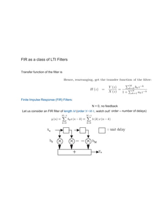
- 1. FIR as a class of LTI Filters Transfer function of the filter is Finite Impulse Response (FIR) Filters: N = 0, no feedback Let us consider an FIR filter of length M (order N=M-1, watch out! order – number of delays)
- 2. Can immediately obtain the impulse response, with x(n)= (n) The impulse response is of finite length M, as required Note that FIR filters have only zeros (no poles). Hence known also as all-zero filters FIR filters also known as feedforward or non-recursive, or transversal Linear-phase filters The ability to have an exactly linear phase response is the one of the most important of FIR filters A general FIR filter does not have a linear phase response but this property is satisfied when four linear phase filter types
- 3. FIR Design Methods • Impulse response truncation – the simplest design method, has undesirable frequency domain- characteristics, not very useful but intro to … • Windowing design method – simple and convenient but not optimal • Optimal filter design methods FIR Design by Optimisation: Least-Square Method The integral of the weighted square frequency-domain error is given by 2 = E2( )d and we assume that the order and the type of the filter are known. Under this assumptions designing the FIR filter now reduces to determining the coefficients that would minimise 2 . We now present a method that approximates the desired frequency response by a linear-phase FIR amplitude function according to the following optimality criterion.
- 4. Example p =0.2 s =0.3 1 =0.1 2 =0.01 Design a type I low-pass filter according to specification passband frequency stopband frequency But assume the pass-band tolerance of 0.1 Least-Square Design of FIR Filters • Meeting the specification is not guaranteed a-priori, trial and error is often required. It might be useful to set the transition bands slightly narrower than needed, and it is often necessary to experiment with the weights • Occasionally the resulting frequency response may be peculiar. Again, changing the weights would help to resolve the problem
- 5. Equiripple Design The least-square criterion of minimising is not entirely satisfactory. A better approach is to minimize the maximum error at each band 2 = E2( )d = max |E( )| The method is optimal in a sense of minimising the maximum magnitude of the ripple in all bands of interest, the filter order is fixed It can be shown that this leads to an equiripple filter – a filter which amplitude response oscillates uniformly between the tolerance bounds of each band
- 6. The weights can be determined in advance from a minimax specification. For example, if a simple lowpass filter has a requirement for the passband gain to be in the range 1- p to 1+ p, and the stopband gain to be less than s, the weightings given to the passband and stopband errors would be s and p respectively. The detailed algorithm is beyond the (time!) constraints of this module. Equiripple Design: Weights 1.625 kHzpassband edge frequency passband pk-to-pk ripple transition width stopband attenuation sampling frequency <1 dB 0.5 kHz >50 dB 8 kHz The passband ripple corresponds to ±6%, while the stopband attenuation is 0.32%, hence the weighting factors are set to 0.32 and 6. Using the relevant length estimation formula gives order N=25.8 hence N=26 was chosen, i.e. length =27. This proved to be substantially too short, and it was necessary to increase the order to 36 (length 37) to meet Example Obtain the coefficients of an FIR lowpass digital filter to meet these specifications: