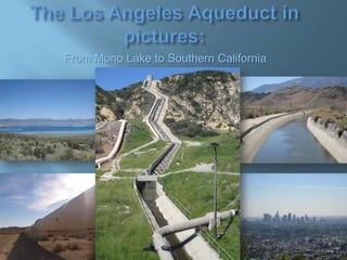
From Mono Lake to Southern California: The Story of the Los Angeles Aqueduct
•
16 gostaram•41,491 visualizações

Follow the path of California's first major water project that stretched from Mono Lake to Southern California, delivering the Owens River to support the growth & population of Los Angeles.

Recomendados
Recomendados
Mais conteúdo relacionado
Mais procurados
Mais procurados (20)
Semelhante a From Mono Lake to Southern California: The Story of the Los Angeles Aqueduct
Semelhante a From Mono Lake to Southern California: The Story of the Los Angeles Aqueduct (20)
Mais de Chris Austin
Mais de Chris Austin (7)
Último
Último (20)
From Mono Lake to Southern California: The Story of the Los Angeles Aqueduct
- 1. From Mono Lake to Southern California
- 2. Conceived, researched, written and (mostly) photographed by Chris Austin Special thanks for all their assistance: Arya Degenhart from the Mono Lake Committee, Ted Schade from the Great Basin Unified Air Pollution Control District, the Inyo County Water Department, Fred Barker of the Los Angeles Department of Water and Power, Mike Prather of the Eastern Sierra Audubon Society, the Water Resources Center Archives at U.C. Berkeley, the Eastern California Museum, Rich McCutchan, and all of the flickr photographers whose photos have made this project possible. Flickr photos used under the Creative Commons license. © Chris Austin, 2009; All Rights Reserved
- 3. In the early 1900‟s, William Mulholland, head of the new domestic water works system for the city of Los Angeles, knew that the meager Los Angeles River could not supply enough water for the city‟s continued growth. He became convinced the only solution was to bring the Owens River water to Los Angeles.
- 4. Water Resources Center Archives University of California Berkeley By using a system of open channels, covered conduits tunnels and pressurized pipelines, Mulholland and the other aqueduct engineers developed a system to deliver the water through the canyons and rugged terrain of the Mojave Desert and the Antelope Valley, delivering the water to Los Angeles entirely by gravity flow. Water Resources Center Archives University of California Berkeley
- 5. Water Resources Center Archives University of California Berkeley Completed in 1913 at a cost of $22 million, the waters of the Owens River were turned into the aqueduct and began flowing into Los Angeles for the first time.
- 6. Water Resources Center Archives University of California Berkeley The Los Angeles Aqueduct was the first major water project built in California. It was an amazing engineering feat at the time, being second in size and significance only to the Panama Canal.
- 7. Mulholland‟s original aqueduct system is still in use today, although the system has been expanded from its original form. In 1941, the Mono Basin project was completed, extending the reach of the aqueduct 105 miles further north to bring water diverted from the Mono basin into the aqueduct system. Photo by Chris Austin Photo by Chris Austin The Second Los Angeles Aqueduct was completed in 1970, further expanding the system in order to take full advantage of the rights DWP held in the Mono Basin. The project included building a second aqueduct from Haiwee Reservoir to the Cascades Facility in Sylmar, thereby increasing the capacity of the system by an additional 50%.
- 8. Photo by Chris Austin Hydroelectric power generation facilities along the aqueduct have been expanded over the years, making the Los Angeles Aqueduct the only system conveying water to Southern California that is a both a source of water and a source of power for the region.
- 9. Historically, the Los Angeles Aqueduct system has been the major source of water supply for Los Angeles city residents. However, in recent years, court-ordered restrictions, mandated uses for mitigation projects and the on-going drought have reduced the amount of water available to be exported to Los Angeles. In 2009, the Los Angeles Aqueduct will supply just 23% of the city‟s water. Photo by Chris Austin
- 10. The Owens Valley water has made the growth of Los Angeles possible, but the dewatering of the Owens Valley has not been without its ill effects on the Owens Valley, as well as on Mono Lake. Photo by Chris Austin
- 11. The export of water south to Los Angeles decimated a thriving agricultural community and dried up Owens Lake. In later years, the extension of the aqueduct system further northward threatened Mono Lake, and increased groundwater pumping caused further environmental degradation within the Owens Valley. Water Resources Center Archives University of California Berkeley
- 12. Photo by Chris Austin Environmental mitigation for the damage done has been litigated for decades, and continues even today. Currently, DWP is under court mandated obligation to keep water in the Lower Owens River and provide dust control on the dry Owens Lake bed. Additional mandates limit the amount of water DWP can draw from the Mono Lake basin, as well as require additional restoration efforts on the lake‟s tributaries.
- 13. Map of California‟s Rivers and Water Systems From the California Department of Water Resources Top of the aqueduct Mono Lake Los Angeles Aqueduct This presentation is intended to give a brief overview of the infrastructure and the issues of the Los Angeles aqueduct system. This presentation will follow the path of the aqueduct from Mono Lake to Southern California. Starting at the top … Terminus of the aqueduct San Fernando Valley California has many other water projects as depicted on this map. To learn more, click here: http://aquafornia.com/wheredoes-californias-water-come-from
- 14. Mono Lake The Los Angeles Aqueduct system begins here, 338 miles north of Los Angeles, at the remote Mono Lake, where DWP holds water rights to the main tributaries of the lake. Photo by Chris Austin
- 15. Mono Lake is the saline remnant of Lake Russell, an ancient freshwater lake which filled the Mono Basin during the Pleistocene epoch. For more about Pleistocene lakes, click here: http://www.britannica.com/EBchecked/topic/464 579/Pleistocene-Epoch/70010/Lacustrineenvironments Photo of Mono Lake by flickr photographer kla4067
- 16. Mono Lake has no outlet, so minerals and trace elements present in the streams that feed into the lake concentrate in the waters. The lake has a ph of 10 and a salinity that is 2 to 3 times greater than that of the ocean. Photo by Chris Austin
- 17. Although the water is too alkaline to support fish, the brine shrimp and the alkali flies are abundant, providing an endless source of food supply for migrating birds. The Mono Lake watershed is home to over 300 species of birds, mostly migratory. Over 100 species nest here as well, including the second largest gull rookery in North America. Photo by flickr photographer Rob Inh00d Millions of birds arrive between mid-summer and fall to feast on the shrimp and flies, gaining weight in preparation for their long, migratory flights. Photo by flickr photographer Billtacular.
- 18. Mono Lake plays a vital role in the annual migration of birds between North to South America, and is designated as part of the Western Hemisphere Shorebird Network, a collection of critical migratory bird habitats in North & South America. With over 95% of California‟s wetlands gone, Mono Lake‟ s importance has increased as it is one of the last remaining "re-fueling" stops along the arid inland Pacific Fly-Way. For more on the birds at Mono Lake, click here: http://www.monolake.org/about/ecobirds Photo by flickr photographer xeeliz
- 19. Mono Lake is also known for its tufa towers, which are formed when the calcium-rich underwater springs mix with the carbonate-rich lake water, creating calcium carbonate (limestone). Photo by Chris Austin The limestone precipitates around the springs, and over the course of decades or longer, a tufa tower will grow. Photo by flickr photographer pluckytree.
- 20. Photo by Chris Austin Tufa towers only grow underwater, where they can reach heights of 30 feet or more. Photo by Chris Austin Find out more about Mono Lake‟s tufa towers here: http://www.monolake.org/about/geotufa
- 21. In 1941, after completion of the Mono Basin project, Los Angeles Department of Water & Power (DWP) began diverting most of the tributaries to the lake. Completion of the second aqueduct in 1970 increased the capacity of the aqueduct system, and diversions from the basin increased dramatically. Photo courtesy of the Mono Lake Committee With the lake being deprived of water, the shoreline began to recede, exposing the tufa towers. By 1982, the water level had declined by 45 feet , leaving the tufa towers stranded and exposing over 17,000 acres of dried lakebed. Photo courtesy of the Mono Lake Committee
- 22. The ecology of the lake suffered as a result. The alkali flies and brine shrimp the birds depended on were at risk, the islands that the birds used for nesting became connected to land making them vulnerable to predators, and the exposed lakebed caused numerous air quality violations. Photo courtesy of the Mono Lake Committee
- 23. Photo by Chris Austin The Mono Lake Committee, the National Audubon Society, Cal Trout and others filed suit on the theory that the shores, bed and waters of Mono Lake were protected by the public trust doctrine, and that Los Angeles‟ diversion of water was in violation of that doctrine. The Supreme Court eventually concluded that the DWP‟s water rights should be re-evaluated.
- 24. On September 28, 1994, the State Water Resources Board issued Decision 1631, which ordered DWP to halt diversions until the lake rose 3 feet. After that, DWP was allowed to divert 15,000 acre-feet per year until the lake reaches 6392 feet. Once that point is reached, DWP will be allowed to divert 30,000 acre-feet per year, about 1/3 the amount they had previously been diverting. Photo by Chris Austin
- 25. Decision 1631 also ordered DWP to develop restoration plans for streams and waterfowl habitat. Photo courtesy of the Mono Lake Committee
- 26. As of October 1st, 2009, Mono Lake was at 6381.7 feet, which is still 9.3 feet below the court mandated level. Photo by Chris Austin
- 27. When that mandated level is reached, it will still be 25 feet lower than Mono Lake was prior to the diversions, but it is expected to be enough to restore the public trust values of “the purity of the air, the scenic views of the lake and shore, and the use of the lake for nesting & feeding birds,” and to prevent further degradation of the watershed. Read more on Mono Lake Basin Water Right Decision 1631 here: http://www.monobasinresearch.org/timelines/d1631.htm Picture of Mono Lake by flickr photographer ryanophilly.
- 28. As part of DWP‟s Mono Basin project, four of Mono Lake‟s tributaries creeks were tapped: Rush, Lee Vining, Parker and Walker creeks. Picture by flickr photograher calwest. Lee Vining Creek is the second largest tributary to Mono Lake. Picture by flickr photographer TTvo.
- 29. Photo courtesy of the Mono Lake Committee. The diversion dam on Lee Vining Creek is located just upstream of the ranger station. It is here that water is diverted into an 8-mile underground conduit that conveys the water to Grant Lake reservoir. Photo courtesy of the Mono Lake Committee.
- 30. Picture of Rush Creek by flickr photographer jcookfisher. Rush Creek is Mono Lake‟s largest tributary.
- 31. Silver Lake June Lakes Loop Photo by Chris Austin It flows from the high Sierra, filling numerous small alpine lakes on its way to Mono Lake.
- 32. Photo by Chris Austin The 47,500 acre-foot Grant Lake Reservoir lies in between Rush Creek and Mono Lake, providing on-stream storage for the waters of Rush Creek, as well as being the termination point of the underground conduit bringing water from the other diverted streams. Water is either stored here, sent south to Los Angeles, or released into Rush Creek.
- 33. One of the requirements of Decision 1631 required restoration of Rush Creek below Grant Lake dam. However, the dam was built to hold and divert water with the only outlet for releasing water into Rush Creek being over the spillway, which can only happen in wetter years. Photo from the Library of Congress, Historical American Engineering Record
- 34. Retrofitting the dam is an expensive process, so the Water Board is allowing DWP to try other methods for delivering the required flows to Rush Creek. Photo courtesy of the Mono Lake Committee.
- 35. Water leaves Grant Dam by the aqueduct conduit, and enters Mono Gate One, where it is split between the aqueduct and Rush Creek. To Mono Lake Rush Creek Rush Creek Return Ditch Mono Gate One Grant Lake Dam
- 36. Dewatered creek This results in about one mile of Rush Creek remaining dewatered downstream of the dam at Grant Lake. Photo courtesy of the Mono Lake Committee
- 37. This is Mono Gate One, where water is returned to Rush Creek from the aqueduct conduit. This facility has been unable to meet the high flow targets as mandated by Decision 1631 and is currently being modified. Photo courtesy of the Mono Lake Committee
- 38. Photo courtesy of the Mono Lake Committee In the meantime, when it is necessary to augment flows to meet the mandated high flow requirements for Rush Creek, a portion of the water diverted from Lee Vining Creek can be diverted into Rush Creek through a structure called the 5-Siphon Bypass.
- 39. The water for Rush Creek is released into the Rush Creek Return Ditch, which flows into the original creek channel and then into Mono Lake. Photo courtesy of the Mono Lake Committee
- 40. Diagram by the Mono Lake Committee. This diagram shows the complicated plumbing for Rush Creek. For more information, visit the Mono Lake Committee online: http://www.monolake.org/
- 41. The aqueduct conduit then passes into the West Portal of the Mono Craters tunnel, which sends the water 11.3 miles underneath a volcanic cone to deliver water to the head of the Owens River.
- 42. Boring the tunnel was a difficult task due to large amounts of groundwater, carbon dioxide gas, and porous formations requiring heavy steel & timber supports. It took six years to complete. Picture by USGS/C.D. Miller Read more on the construction of the Mono Crater Tunnels here: http://www.monobasinresearch.org /historical/monobasinproject.pdf
- 43. From the Library of Congress, Historic American Engineering Record.
- 44. The water flows out of the Mono Craters tunnel … Photo courtesy of the Mono Lake Committee
- 45. … and joins the headwaters of the Owens River, flowing south towards Bishop. Photo by flickr photographer acidwashtofu.
- 46. On the way, it flows past the Hot Creek Fish Hatchery, created as compensation for fish losses as a result of the building of the Grant Lake and Crowley Lake reservoirs. Photo by flickr photographer oniondeath.
- 47. Photo by USGS For more information on volcanic activity in the area, visit the USGS at http://lvo.wr.usgs.gov/ The hot springs at Hot Creek are a sign of the ongoing volcanic processes in the region.
- 48. The water temperature of the springs is ideal for trout development. Each year, the Hot Creek Fish Hatchery plants 3 million trout throughout the Sierra Nevada, and provides 20 million eggs for other fish hatcheries throughout the state. Photo by flickr photographer oniondeath.
- 49. It is one of the most productive fish hatcheries in California. Photo by flickr photographer oniondeath. Photo by flickr photographer oniondeath. Find out more about California‟s fish hatcheries here: http://www.dfg.ca.gov/fish/Hatche ries/index.asp
- 50. The Owens River then flows into the Crowley Lake reservoir. Crowley Lake Photo by Chris Austin.
- 51. Photo by Chris Austin The Long Valley Dam was built as part of the Mono Basin project, creating Crowley Lake reservoir. Photo by Chris Austin
- 52. Photo by Chris Austin. At 183,000-acre-feet, Crowley Lake is the largest reservoir in DWP‟s water system, providing storage for the combined Mono basin & Owens River waters.
- 53. Crowley Lake is a popular fishing lake with a premier trout fishery, attracting thousands of anglers throughout the season. Photo by flickr photographer vrkrebs.
- 54. At the south end of Crowley Lake, the river then enters the Owens Gorge. Photo by Aquafornia. Photo by Chris Austin.
- 55. The gorge was formed by the river cutting through the Bishop Tuff, a volcanic tableland of welded ash deposited from the eruption of the Long Valley volcano. Photo by flickr photographer cpt.spock.
- 56. Photo by Chris Austin DWP has built three power plants in the Owens Gorge to take advantage of the 2400-foot elevation drop between Crowley Lake and the Owens River Valley.
- 57. The three power plants are connected by penstocks that travel above ground and through tunnels in between the three power plants. Photo by Chris Austin. Photo by Chris Austin.
- 58. Penstock This aerial shot of the Middle Gorge Power Plant shows the penstock coming from the Upper Gorge plant on its way to the Middle Gorge Plant. Afterwards, it emerges further down the gorge, where it will become the penstock for the Control Gorge plant, the last power plant in the chain of three. Middle Gorge Power Plant Photo from the Library of Congress, Historical American Engineering Record
- 59. Photo by Chris Austin This is the penstock coming down from the gorge and headed into a turbine at the Control Gorge power plant.
- 60. Photo by Chris Austin The Control Gorge power plant is at the bottom of the Owens Gorge. For more on hydroelectric power, click here: http://ga.water.usgs.gov/edu/hyhowworks.html Photo by Chris Austin
- 61. From the Library of Congress, Historic American Engineering Record. The aqueduct system has been extensively developed to take advantage of the drop in elevation as water descends from the High Sierra to Los Angeles. The aqueduct‟s 14 power plants provided Los Angeles with over 400 million kWh of hydroelectric power in 2008.
- 62. From the Library of Congress, Historic American Engineering Record.
- 63. Photo by Chris Austin. After the Control Gorge power plant, the river then flows into the Pleasant Valley reservoir. The Pleasant Valley Dam was built in conjunction with hydroelectric development in the Owens Gorge. Photo by Chris Austin.
- 64. Photo by Chris Austin. The reservoir allows the upstream power plants to increase or decrease water flow for power production as needed without causing rapid fluctuations in the flow of the Owens River below. Photo by Chris Austin. A small power plant produces power when water is released from the reservoir.
- 65. Photo by Chris Austin. The Owens River then leaves Pleasant Valley reservoir … … and heads south towards Bishop. Photo by Chris Austin.
- 66. DWP owns 314,000 acres in the Owens Valley, making it the largest private landowner in the watershed. Photo by Chris Austin.
- 67. Photo by Chris Austin Photo by flickr photographer Christian Panama. Much of the land is open for recreational use, such as fishing, boating, hiking, and rock climbing. Photo by Chris Austin Photo by Aquafornia
- 68. DWP leases a portion of the land for ranching operations. Photo by Chris Austin Leaseholders must adhere to strict guidelines designed for maximum protection of the watershed. Photo by Chris Austin.
- 69. Photo by Chris Austin. DWP provides land for city & county parks, golf courses, museums and visitor centers, including the Eastern California Museum and the Inter-Agency Visitors Center. Some of the land is also leased to area businesses. Photo by Chris Austin.
- 70. Photo by Chris Austin. At the Eastern California Museum in Independence, there is an exhibit on the building of the aqueduct, as well as exhibits of Native American basketry and artifacts, early Eastern Sierra residents and pioneers, a Manzanar exhibit, a native plant garden, and a large photo collection.
- 71. The museum also has an equipment yard featuring farming and mining implements, as well as some aqueduct construction equipment. Photo by Chris Austin. Visit the Eastern California Museum online at: http://www.inyocounty.us/ecmuseum/
- 72. Down the road at the Inter-Agency Visitor Center in Lone Pine, DWP is one of several agencies displaying information about the Eastern Sierra … Photo by Chris Austin Photo by Chris Austin
- 73. For more information on this and other visitor centers in the area, click here: http://www.fs.fed.us/r5/inyo/about/ Photo by Chris Austin. … which includes a large relief map showing the path of the aqueduct, as well as other Eastern Sierra landmarks.
- 74. Photo by flickr photographer verno_64 Bishop The water‟s journey continues past Bishop, staying in the river‟s natural channel until it reaches the aqueduct intake above Independence.
- 75. Two miles north of the town of Big Pine is Klondike Lake, a mitigation project maintained by DWP to provide nesting and feeding areas for waterfowl. It is also used for recreation and water sports. Photo by Chris Austin. For more information on Klondike Lake, click here: http://www.schweich.com/geoCAInyKlondikeLk.html
- 76. South of Big Pine is the Fish Springs Hatchery, another Eastern Sierra hatchery producing fish which will be stocked in the area‟s lakes and rivers. Photo by Chris Austin. Photo by Chris Austin.
- 77. Photo from the Library of Congress, Historical American Engineering Record The Tinemaha Reservoir is located six miles north of the aqueduct intake. It was completed in 1928, and can store 6300 acre-feet of water.
- 78. Tinemaha Reservoir provides for storage and regulation of water into the aqueduct intake downstream.
- 79. Photo by Chris Austin. Intake North of the town of Independence are the headworks and intake for the aqueduct. This is where the Owens River water leaves its natural course and begins its journey southward through the aqueduct infrastructure.
- 80. Photo by Chris Austin. There is a 325-foot diversion weir which directs the flow of the river into the aqueduct intake.
- 81. Lower Owens River Diversion weir This is an overview of the intake structure, showing how the diversion weir blocks the river from continuing in its own channel and directs it to the aqueduct intake instead. Aqueduct Intake Photo courtesy of the Inyo County Water Department.
- 82. From the Library of Congress, Historic American Engineering Record.
- 83. Photo by Chris Austin. Besides surface water rights, DWP also owns extensive groundwater rights and has drilled wells throughout the Owens Valley. After completion of the second aqueduct in 1970, DWP dramatically increased groundwater pumping. The groundwater withdrawals caused the water table to drop; as a result, widespread environmental damage occurred: springs and meadows dried up, and native vegetation began to die.
- 84. In 1991, DWP & Inyo County entered into the Long Term Water Agreement to manage the groundwater and avoid further significant impacts. The agreement also specified several mitigation projects, one of those being restoration of the Lower Owens River. . For more on DWP‟s groundwater pumping management in the Owens Valley, click here: http://www.inyowater.org/pumping.htm Photo by Chris Austin.
- 85. This was the Lower Owens River in 2006 …. Photo by flickr photographer im me.
- 86. … and this is the Lower Owens River today. Photo by Aquafornia
- 87. Under the Inyo/Los Angeles Long Term Water Agreement, the County and DWP committed to re-water the full 60 miles of the river below the aqueduct intake. Photo by Chris Austin.
- 88. This required modifications to the intake structure to allow water to be released into the river channel, as the original structure was designed to divert the entire flow of the river into the aqueduct. Photo courtesy of Inyo County Water Department.
- 89. Photo courtesy of Inyo County Water Department. The agreement requires that DWP maintain flows of 40 cfs as measured by ten different flow gauges installed along the river. Photo by Chris Austin.
- 90. Additionally, DWP is required to provide permanent water supplies to lakes and ponds, and to two waterfowl and shorebird habitats with water supplied from the aqueduct. Photo courtesy of Inyo County Water Department.
- 91. In December of 2006, Mayor Villiaragosa himself was on hand along with DWP‟s David Nahai when water was diverted back into the Lower Owens River for the first time in nearly a hundred years. Mayor Villaraigosa returned on Valentine‟s Day in 2008 to canoe down the restored river. Photo courtesy of Mayor Villiaragosa.
- 92. Where the river enters Owens Lake, a pump station captures the flows from the river, where it is either diverted to the Owens Lake dust control project, put back into the aqueduct, or allowed to flow into the Owens Lake delta. For more on the Lower Owens River Project, click here: http://www.inyowater.org/LORP/default.htm
- 93. Aqueduct intake Back at the intake, the water leaves the channel of the river and takes a straight path across the valley towards the Alabama Gates. Aqueduct Lower Owens River
- 94. Photo by Chris Austin. The water will travel by gravity 233 miles to Los Angeles, passing through power plants, conduits, pressurized pipelines, tunnels and reservoirs along the way. Photo by Chris Austin.
- 95. The water traverses part of the valley in an unlined, earthen canal. Photo by Chris Austin.
- 96. From the Library of Congress, Historic American Engineering Record.
- 97. Photo by Chris Austin. At the Alabama Gates located just north of Lone Pine, water can be diverted from the aqueduct into a spillway that leads to the Owens River. The Alabama Gates are also notable as being the scene of one of the more colorful episodes in the history of the aqueduct.
- 98. The diversion of water from the Owens Valley to Los Angeles met with resistance from many of the local residents who were seeing their way of life dry up as the water left the valley. In 1924, locals took over the facility and opened the gates, sending the entire flow of water down the spillway and back into the dry river channel. Photo from collection at the Eastern California Museum.
- 99. Lawmen sent to retake the facility were rebuffed, and soon a party atmosphere ensued, lasting for days. The crowd swelled to as much as 1500 as wives brought picnic dinners for their husbands and local businessmen closed up shop to join the crowd. A film star working on a film in the area even sent a band. Eventually order was restored, the gates were closed, and water once again flowed south to Los Angeles. Photo from collection at the Eastern California Museum.
- 100. Photograph courtesy of Rich McCutchan But unfortunately, that wasn‟t the end of the conflict. When the long and often bitter negotiations broke down, angry residents responded by dynamiting the aqueduct numerous times, even at one point prompting the City to send out armed guards to patrol the aqueduct system.
- 101. Photo from collection at the Eastern California Museum. Eventually, the disputes between the valley residents and city officials moved to the courts, where most issues were resolved. However, while relations between the residents and DWP have improved over the years, disputes and wrangling over the valley‟s limited water resources still continue even today. For more on Owens Valley issues, click here: http://www.ovcweb.org/
- 102. Photo by Chris Austin. Aqueduct Alabama Gates South of the Alabama Gates, the aqueduct leaves the valley floor and begins to run along the hillsides. The floor of the valley and the Owens River continue dropping towards Owens Lake. The difference in elevation between the aqueduct and the river begins to grow.
- 103. When the aqueduct leaves the valley floor, it also leaves the water table below it. In order to not lose all its water to seepage, the aqueduct now travels in a concrete-lined canal. Photo by flickr photographer calwest.
- 104. Photo by Chris Austin. The path of the aqueduct now travels through several Pleistocene-era shorelines of Owens Lake. The gravels and sand in this area were used to make the concrete needed for canal lining.
- 105. Aqueduct Photo by Chris Austin. The aqueduct passes by Diaz Lake, a natural lake formed by the 1872 Lone Pine earthquake, when the ground dropped 20 feet, giving the creek a basin to fill.
- 106. Photo by Chris Austin. The lake is located just south of Lone Pine, and is used for fishing, water sports, and camping.
- 107. Photo from collection at the Eastern California Museum. Owens Lake The Owens Lake is part of a chain of ancient Pleistocene lakes that extended from Mono lake south down into Death Valley. Since that time, the lake‟s level had been diminishing, but by the late 1800s, Owens Lake was still one of California‟s largest natural lakes, covering 110 square miles. It was a saline terminal lake with a salinity 1 ½ times greater than that of the ocean.
- 108. Photo courtesy of Great Basin Unified Air Pollution Control District. After the entire flow of the Owens River was diverted to Los Angeles in 1913, the Owens Lake began to shrink, and by 1928, the lake bed was dry. Photo courtesy of Great Basin Unified Air Pollution Control District.
- 109. Photo courtesy of Great Basin Unified Air Pollution Control District. The dry lake bed became notable for being the largest single source of particulate matter in the U. S., emitting over 80,000 tons per year of particulate matter into the air with 24-hour concentrations as high as 130 times the federal air quality standards.
- 110. Photo courtesy of Great Basin Unified Air Pollution Control District. In the five years from 2000 to 2004, 78 of the 100 highest 24-hour PM-10 concentrations (or dust events) measured in the United States occurred at Owens Lake. 21 of the remaining 22 days occurred at Mono Lake.
- 111. Photo courtesy of Great Basin Unified Air Pollution Control District. The PM-10 particulate matter from the Owens Lake bed is a toxic mix of arsenic, cadmium, nickel and sulfates, affecting up to 40,000 residents and visitors. If the conditions are right, Owens Lake particulate emissions can even travel to the more densely populated areas of Southern California.
- 112. PM-10 particles are small enough to penetrate the lungs deeply, and can cause a variety of breathing problems, especially in sensitive populations. During dust events, residents of the surrounding area are advised to stay inside and avoid outdoor strenuous activities. Photo courtesy of Great Basin Unified Air Pollution Control District.
- 113. Picture courtesy of Great Basin Unified Air Pollution Control District. In 2000, DWP began dust control measures on the lake bed to bring the area into compliance with federal air quality standards.
- 114. Photo courtesy of Great Basin Unified Air Pollution Control District. Dust control measures being applied include shallow flooding….
- 115. … native vegetation, Photo courtesy of Great Basin Unified Air Pollution Control District. and laying down a gravel blanket. Photo courtesy of Great Basin Unified Air Pollution Control District.
- 116. Photo courtesy of Great Basin Unified Air Pollution Control District. Saltgrass, a locally adapted native plant, is being cultivated on parts of the lake bed. Drip irrigation and micro sprinklers are used to minimize water consumption. Photo courtesy of Great Basin Unified Air Pollution Control District.
- 117. To date, DWP has spent $600 million on dust control measures for 19,000 acres of dry lakebed; this will expand to 29,000 acres over the next 2 years. Ongoing operations are expected to cost DWP $20 million and 65,000 acre-feet of water annually. Photo by Chris Austin.
- 118. Photo by Mike Prather It is making a difference. Ten years ago, federal air quality standards were violated over 30 times. Last year, there were only 9 violations, and peak 24-hour PM-10 levels have been reduced 90%.
- 119. Photo by Mike Prather The shallow flooding of the lake bed is also bringing back the wildlife. Photo by Mike Prather Photo by Mike Prather
- 120. In April of 2009, Eastern Sierra Audubon Society volunteers counted 61,983 birds of 74 different species using the dust control areas. Photo by Mike Prather Visit the Eastern Sierra Audubon Society online at: http://esaudubon.org/ Photo by Mike Prather
- 121. DWP is looking at other measures of controlling dust, such as using trenches and berms in a technique called „moat and row‟, or pumping the brackish water from underneath the lake and spreading it on the dry lake bed. DWP is even considering installing solar panels to act as a windbreak. For more on Owens Lake dust control, click here: http://www.gbuapcd.org/ Photo by Chris Austin.
- 122. The Cottonwood Creek Power Plant starting generating power on November 13, 1908, supplying energy for aqueduct construction. The very same generators remain in operation today. Photo by Chris Austin
- 123. Photo by Chris Austin. The power plant generates its power by diverting Cottonwood Creek into a flume 4 miles up the canyon. The water then flows into a forebay. through the penstocks into the power plant, and directly into the aqueduct. Photo by Chris Austin.
- 124. Past Owens Lake and just south of Olancha, the aqueduct turns underneath Highway 395 and heads towards Haiwee Reservoir. Photo by Chris Austin.
- 125. Photo by Chris Austin Originally, Haiwee Reservoir was a single reservoir. It was separated as part of the building of the second aqueduct to increase operational flexibility.
- 126. There is a dam and another power plant at the south end of the reservoir. Photo from the Library of Congress, Historical American Engineering Record
- 127. The second aqueduct is fed by North Haiwee Reservoir and enters steel pipe and concrete conduit after leaving Haiwee.
- 128. The first aqueduct is normally fed by South Haiwee Reservoir and enters a buried conrete conduit after passing through the power plant. A bypass channel is used to divert water around South Haiwee Reservoir when needed. Bypass Channel
- 129. Photo by Chris Austin. The concrete top of the first aqueduct‟s conduit can be seen above ground, while the second aqueduct‟s conduit is buried.
- 130. From the Library of Congress, Historic American Engineering Record.
- 131. From the Library of Congress, Historic American Engineering Record. The first aqueduct will now make its way to Los Angeles through 98 miles of concrete conduit, 12 miles of steel & concrete pipeline, and 52 miles of tunnels. The solid line represents the path of the first aqueduct; the dotted line represents the path of the second aqueduct.
- 132. Tunneling was used extensively during construction of the first aqueduct because at the time, labor was cheap and plentiful, but materials, such as steel pipeline, were much more expensive. Tunneling was the more economical choice. Water Resources Center Archives University of California Berkeley
- 133. The pipeline portions of the original aqueduct were constructed of reinforced, cast-in place concrete pipe and riveted steel pipe, both of which are still in use. The original coating is black. In other areas, it has been repainted. All of the coating of the steel pipe is being replaced. Photo by Chris Austin. Photo by Chris Austin.
- 134. About 12 miles of steel and concrete pressure pipelines were used to cross twenty-three canyons and valleys on the original aqueduct where other methods would have been more expensive. Mojave Desert Nine mile siphon Photo by Chris Austin
- 135. The pressure pipelines used to cross canyons and valleys use varying amounts of head differential to push water through them. The amount of head varied with the length and diameter of the pipelines. In some cases, tapered-diameter steel pipelines were used to minimize the tonnage of steel required compared to constant diameter pipelines. Photo by Chris Austin.
- 136. Water flows through the aqueduct pressure pipelines in the desired direction because the upstream end of each pipeline is higher than the downstream end. Direction of travel Photo from the Library of Congress Historical American Engineering Record From the Library of Congress, Historic American Engineering Record.
- 137. Photo by Chris Austin. The pipeline at Jawbone Canyon is about 8,000 feet long and is the deepest on the original aqueduct at 850 feet. Photo by Chris Austin.
- 138. The Antelope Valley siphon is the longest siphon at 4.11 miles in length. Photo by Chris Austin.
- 139. From the Library of Congress, Historic American Engineering Record.
- 140. The first Los Angeles Aqueduct crosses the State Water Project‟s California Aqueduct near Neenach at the southwestern end of the Antelope Valley. For more information on the State Water Project, click here: http://www.water.ca.gov/swp/index.cfm Photo by Chris Austin.
- 141. The second aqueduct travels through 64 miles of concrete conduit, 69 miles of steel pipeline, and 4 miles of other facilities. It is made of welded steel and is painted desert tan. Second Aqueduct at Jawbone Canyon Photo by Chris Austin.
- 142. It runs mostly underground, only emerging when necessary to cross washes and canyons. Photo by Chris Austin.
- 143. When the surveys and studies were done to assess the best route for the second aqueduct, engineers chose a path very similar to that of the first aqueduct. Photo from the Library of Congress, Historical American Engineering Record
- 144. Photo by Chris Austin. First aqueduct Second aqueduct However, changes in relative costs of materials and labor meant the greater use of steel pipe and less tunneling compared to the original aqueduct.
- 145. Photo by Chris Austin. The second aqueduct added 50% capacity to the aqueduct system. By providing more flow over longer periods of time, it also added 200 million kWh of hydropower generation.
- 146. Because pipe was cheaper when the second aqueduct was built, a shorter, more direct path across the Antelope Valley was taken, rather than the circuitous route that was necessary when building the first aqueduct. The solid line represents the first aqueduct; the dotted line represents the second aqueduct. The Second Aqueduct in the Antelope Valley Photo by Chris Austin. From the Library of Congress, Historic American Engineering Record.
- 147. Both aqueducts meet at the Fairmont Reservoir in the south Antelope Valley. The output from this reservoir is a gate tower to the North Portal of the Elizabeth Tunnel. California Aqueduct Photo from the Library of Congress, Historical American Engineering Record
- 148. The Elizabeth Tunnel carries water through the Coast Range, traveling 5 miles and 250 feet below Elizabeth Lake. The tunnel was the longest on the first aqueduct. Elizabeth Tunnel Photo by Chris Austin.
- 149. Water Resources Center Archives University of California Berkeley With an incentive program in place for working fast, the tunnel drillers set the world‟s record for hard rock tunnel drilling at 604 feet in one month, and even finished 20 months ahead of schedule, saving thousands of dollars in the process. The five-mile tunnel was drilled from both ends simultaneously. When the two tunnels met in the middle, the center line was only off by 1-1/8”, and the grade was off only by 5/8”.
- 150. The outlet of the Elizabeth tunnel is a pressure canal into the penstock of San Francisquito Power Plant #1. Photo by Chris Austin.
- 151. Photo by Chris Austin. This power plant is the largest on the aqueduct. It began generating power on March 19, 1917, and was DWP‟s first source of municipally generated power for the city.
- 152. An inlet/outlet line is connected from below the surge chamber of power plant #1 to the Bouquet Reservoir, allowing water to be stored at the reservoir for hydroelectric power generation. Photo by Chris Austin
- 153. The 36,500 acre-foot Bouquet Reservoir also provides critical storage downstream of the San Andreas fault. Photo by Chris Austin.
- 154. The water then flows through a tunnel from the first power plant to San Francisquito Power Plant #2. Photo by Chris Austin.
- 155. Next to Power Plant #2 is a historical marker commemorating the collapse of the St. Francis Dam, considered one of California‟s worst disasters. Over 450 people were killed in 1928 when the 185-ft concrete dam structure failed, sending a wall of water down the Santa Clara River valley 54 miles to the sea. Photo by Chris Austin.
- 156. Behind the power plant is a hiking trail which will take you to see what is left of the dam. Photo by flickr photographer tkksummers. More on the St. Francis Dam disaster at this site: http://www.sespe.com/damdisaster/index.html Photo by flickr photographer tkksummers.
- 157. The aqueduct passes through Santa Clarita, an area that has developed around the aqueduct‟s infrastructure. Photo by Chris Austin. Soledad Siphon ‘Photo by Chris Austin.
- 158. Cascades The water enters the San Fernando Valley at the Cascades facility at the north end of the San Fernando Valley. The cascades from the top of the hill were built for the second aqueduct. Photo by Chris Austin.
- 159. Off to the side and lower on the hillside are the cascades for the first aqueduct. Photo by Chris Austin
- 160. Photo by Chris Austin. This is where William Mulholland stood and spoke his famous words “There it is, take it!” as the Owens River water flowed into the San Fernando Valley for the first time.
- 161. Photo from the Library of Congress, Historical American Engineering Record At the Cascades, the water flows over the cement blocks and stones in the process of aeration and energy dissipation.
- 162. The cascades for the Second Los Angeles Aqueduct were built 350 feet higher than the original, which made a gravity supply possible to areas of the north San Fernando Valley that had previously needed a pumped supply. Photo by Chris Austin
- 163. From the Library of Congress, Historic American Engineering Record.
- 164. The journey ends at the filtration plant and the Los Angeles Reservoir. It has taken up to three months for water originating from the Mono Lake basin to arrive here.
- 165. Photo by Chris Austin. In 1971, the First Los Angeles Aqueduct was named as a National Historic Civil Engineering Landmark.
- 166. Mulholland Fountain Griffith Park, Los Angeles The Los Angeles Aqueduct made the growth of the city of Los Angeles possible. It was conceived and built in the days when settling the west was a national goal and the “greater good for the greater number” was the predominant way of thinking. Some say that Los Angeles stole the water from the Owens Valley, and whether this is true or not is a subject of debate. Others say that the land management policies of the DWP have discouraged extensive urban development, and have thus preserved the Owens Valley as a rural recreational paradise. Photo by Chris Austin. Deprived of the water necessary for economic growth and urbanization, Inyo County remains one of California‟s least populated counties.
- 167. Picture by ah zut (flickr) The Eastern Sierra is so much more than just the aqueduct! Visit these websites for more information: http://www.monocounty.org/ http://www.theothersideofcalifornia.com/ http://www.visitmammoth.com/ Photo by Chris Austin. Photo by extremeline.com Picture by Ko Kong (flickr) Photo by Chris Austin
- 168. Los Angeles Dept. of Water & Power Resources: DWP Website: http://www.ladwp.com/ladwp/cms/ladwp004409.jsp Aqueduct operating conditions & reports: http://www.ladwp.com/ladwp/cms/ladwp007321.jsp DWP‟s Owens Valley Operations Report, May 2009: http://www.ladwp.com/ladwp/cms/ladwp012189.pdf Engineering reports: The engineering report for the first aqueduct is available for checkout at the County of Los Angeles Public Library. The engineering report for the second aqueduct is available only as a reference book at the California History Resources Center at the Rosemead branch of the County of Los Angeles Public Library. Library of Congress: Information & pictures available from the „American Memory‟ and „Built In America‟ collections at the Library of Congress. Search “Los Angeles Aqueduct” on this page: http://memory.loc.gov/ammem/browse/index.html Los Angeles Aqueduct in Elsmere Canyon: http://www.elsmerecanyon.com/aqueduct/aqueduct.htm
- 169. From the DWP: The Story of the L. A. Aqueduct: http://www.ladwp.com/ladwp/cms/ladwp001006.jsp History of Water and Power in L.A.: http://www.ladwp.com/ladwp/cms/ladwp001559.jsp Historical collection of pictures archived at the City Library: http://www.lapl.org/resources/en/dwp.html Slideshow on William Mulholland and the building of the aqueduct: http://www.ladwp.com/ladwp/cms/ladwp007239.pdf Other resources: Owens Valley history pages: http://www.owensvalleyhistory.com/ov_aqueduct1/page18.html Owens Valley wikipedia entry: http://en.wikipedia.org/wiki/Owens_Valley Historical collections of pictures archived at the Water Resources Center Archives: http://www.lib.berkeley.edu/WRCA/aqueduct.html Books: Cadillac Desert by Marc Reisner The Water Seekers by Remi Nadeau Water & Power by William L. Kahrl Owens Valley Revisited: A Reassessment of the West's First Great Water Transfer by Gary Libecap
- 170. The Owens Valley Committee: http://www.ovcweb.org/ Great Basin Unified Air Pollution Control District: http://www.gbuapcd.org/ Also see this Owens Lake 2005 status report: http://www.gbuapcd.org/owenslake/OwensLakeStatusAug2005.pdf Inyo County Water Department: http://www.inyowater.org/ LA DWP groundwater pumping: http://www.inyowater.org/pumping.htm Lower Owens River Project: http://www.inyowater.org/LORP/default.htm Eastern Sierra Audubon Society: http://esaudubon.org/
- 171. The Mono Lake Committee: http://www.monolake.org/ The Mono Basin Clearinghouse (research & legal documents): http://www.monobasinresearch.org/ GORP: Mono Basin National Scenic Area: http://gorp.away.com/gorp/resource/us_national_forest/ca/see_in y2.htm Mono Lake State Natural Preserve: http://www.parks.ca.gov/?page_id=514 USGS Long Valley Observatory: http://lvo.wr.usgs.gov/ Owens Valley and Mono Inyo Craters: Photography of a geological journey: http://www.its.caltech.edu/~meltzner/owens/ Cenozoic/Mesozoic Volcanism of the Eastern Sierra Nevada : http://geology.csupomona.edu/docs/sierra.html
- 172. This has been an exclusive presentation by Chris Austin and Maven‟s Manor Productions Check out my California water, science, and policy blog: www.MavensNotebook.com And my photoblog at www.MavensPhotoblog.com Thank you for looking! © Chris Austin, 2009. All Rights Reserved.
- 173. Also available online Follow the path of water as it flows from the Colorado River, through the fertile fields of the Imperial Valley and on to the Salton Sea by clicking here. How is electricity generated and delivered to our homes? Click here to find out! In the world of California water, we‟re always arguing about the Delta. What is the Delta and why is it important? Find out by clicking here. Hottest, driest, lowest. Death Valley is all of these. Check out the wonders of Death Valley by clicking here.