Manual de Recarga Samsung ML 2010 | ML 1610 | SCX 4521F | ML 2010D3
•
0 gostou•924 visualizações

Manual utilizado nos modelos ML 2010D3 para impressoras ML 2010 | ML 1610 | SCX 4521F.

Recomendados
Mais conteúdo relacionado
Mais de Valejet
Mais de Valejet (20)
Último
Último (20)
Manual de Recarga Samsung ML 2010 | ML 1610 | SCX 4521F | ML 2010D3
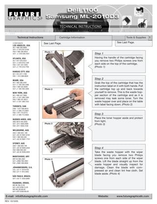
- 1. DELL1100TECH Technical Instructions Cartridge Information Tools & Supplies 1 CORPORATE See Last Page. See Last Page. LOS ANGELES, USA US 1 800 394.9900 Int’l +1 818 837.8100 FAX 1 800 394.9910 Photo 1 Int’l +1 818 838.7047 Step 1 ATLANTA, USA Having the handle of the cartridge facing US 1 877 676.4223 you remove two Philips screws one from Int’l +1 678 919.1189 FAX 1 877 337.7976 each side on the top of the cartridge. Int’l +1 770 516.7794 (Photo 1) KANSAS CITY, USA US 1 913 871.1700 FAX 1 913 888.0626 MIAMI, USA Step 2 US 1 800 595.4297 Grab the top of the cartridge that has the Int’l +1 305 594.3396 FAX 1 800 522.8640 instruction label on it with both hands. Pull Int’l +1 305 594.3309 Photo 2 the cartridge top up and back towards NEW YORK, USA yourself to remove. This is the waste hop- US 1 800 431.7884 per section of the cartridge and as it is Int’l +1 631 588.7300 FAX 1 800 431.8812 removed may leak some toner. Turn the Int’l +1 631 588.7333 waste hopper over and place on the table with label facing down. (Photo 2) TORONTO, CAN CAN 1 877 848.0818 Int’l +1 905 712.9501 FAX 1 877 772.6773 Int’l +1 905 712.9502 Step 3 BUENOS AIRES, ARG Place the toner hopper aside and protect ARG 0810 444.2656 from light. Int’l +011 4583.5900 Photo 3 (Photo 3) FAX +011 4584.3100 MELBOURNE, AUS AUS 1 800 003. 100 Int’l +62 03 9561.8102 FAX 1 800 004.302 Int’l +62 03 9561-7751 SYDNEY, AUS AUS 1 800 003.100 Int’l +62 02 9648.2630 Step 4 FAX 1800 004.302 Int’l +62 02 9548.2635 Take the waste hopper with the wiper MONTEVIDEO, URY blade facing you remove two Philips URY 02 902.2001 Photo 4 screws one from each side of the wiper Int’l +5982 902.2001 blade. Lift the blade straight up from the FAX +5982 900.0858 waste hopper and visually inspect for JOHANNESBURG, S.A. damage. Clean the blade with com- S.A. +27 11 974.6155 FAX +27 11 974.3593 pressed air and clean lint free cloth. Set blade aside. (Photo 4) SÃO PAULO, BRAZIL Int’l +55 11 5524.8000 RAANANA, ISRAEL ISR 09 760.12.39 Int’l +972 9760.12.39 ISR 052.38.555.82 Int’l +972 5238.555.82 E-mail: info@futuregraphicsllc.com Website: www.futuregraphicsllc.com REV. 10/10/05
- 2. 2 Dell 1100 Technical Instructions Photo 7 Step 7 Using a small flat blade screwdriver pry the end cap off carefully. The end caps Step 5 contain the drum axles. (Photo 7) Clean the remaining waste toner from the waste hopper using a vacuum or compressed air. Careful not to damage the retaining blade in the waste hopper, opposite the wiper blade that was removed. Inspect the retaining blade after Photo 8 cleaning to insure that it is Step 8 straight and not damaged. Rotate the cartridge so that the opposite (Photo 5) end is facing you with the handle of the cartridge to the left. Remove two Philips screws that are holding the end cap in place. Using a small flat blade screwdriv- Photo 5 er pry the end cap off carefully. (Photo 8) Photo 9 Step 9 Rotate the cartridge so that the handle of the cartridge is facing you. Grasp the PCR shaft and slide it towards your left to remove it from the right PCR saddle. To remove the PCR from the left PCR saddle, lift the PCR up on the right side to clear Step 6 movement and move towards the right to Taking the wiper blade that is to remove the PCR. (Photo 9) be installed pad the blade with padding powder. Reinstall the blade using two Philips screws Photo 10 one on each side of the blade. Step 10 Place completed waste hopper Remove the drum by pushing up on the aside. helical gear with your finger enough to Set the toner hopper with the grab the entire gear. Pull the drum away long handle towards your right slightly from the opposite side and lift and remove two Philips screws completely out. Set the drum aside in a that are holding the end cap in protective area. (Photo 10) place. (Photo 6) Photo 6 Photo 11 Step 11 Rotate the cartridge so that the handle is facing towards your left and remove the fill plug from the end cap. Clean out all remains of toner from the inside of the toner hopper. Place the fill plug aside for later. (Photo 11)
- 3. Dell 1100 Technical Instructions 3 Photo 12 Step 12 On the cartridge end that contains the fill plug and electrical contacts, push up the Step 17 wire that contacts the developer roller shaft. Release the clip that holds the black Place the cartridge with the car- contact support plate by pushing the tab tridge handle facing you and the in from the outside of the cartridge. Gently handle extended outward. On pull forward on the plate to remove. the right side push the electrical (Photo 12) contact wire forward and to the right to rest just out of the way of the Dr. Bar so that you can Photo 13 install the blade. Install the Step 13 blade by lining up the location Remove the developer roller drive gear pins on each side and coming from the developer roller using a small flat straight down. Hold in place by blade screwdriver to push with. The cen- inserting the two Philips screws ter idle gear in the gear train is loose and one on each side of the Dr. Bar. can fall off so take it off and place aside. Move the electrical contact wire The smaller helical diameter teeth face back into position. (Photo 17) inward. (Photo 13) Photo 17 Photo 14 Step 14 Remove the developer roller by holding the metal shaft on either end and pulling upward. (Photo 14) Step 15 Start by placing the cartridge with the car- tridge handle facing you and the handle extended outward. Remove two Philips Photo 15 Step 18 screws one from each side of the Dr. Bar. Lift carefully from the left side up off the Holding the developer by the location pin just enough to clear it. shaft on each side position and Holding the Dr. Bar steady work towards install the developer roller. Push the right and lift straight up off the locator down with just a little pressure pin and back towards you. This will allow to set and replace the develop- the electrical contact wire to rest in the tab er roller idle and drive gear. slot of the cartridge. Clean with 99% (Photo 17) Isopropyl alcohol and a lint free cloth. (Photo 15) Photo 18 Photo 16 Step 16 Clean the toner hopper area which includes the toner feed roller, developer roller recovery blade, sealing felts, PCR saddles and toner tank area. Be very care- ful not to damage these parts by using too strong of an air flow. (Photo 16)
- 4. 4 Dell 1100 Technical Instructions Photo 21 Step 21 Place the cartridge with the cartridge han- dle facing you and the handle extended Step 19 outward. Place the drum into the cartridge with the helical gear to your right. Moving to the electrical contact (Photo 21) end of the cartridge push the electrical contact wire up out of the way and replace the black Step 22 contact support plate by push- With the longer shaft of the PCR on your ing the black contact support Photo 22 left side install the shaft into the left side plate in until it latches. Bring the PCR saddle enough so that you can clear electrical contact wire down the right side of the cartridge. Pull the and in contact with the metal right side saddle up enough so that you shaft end of the developer roller. can push the PCR towards your right and (Photo 19) into the saddle until it stops. Place a little conductive grease on contact of PCR saddle before installing. (Photo 22) Photo 19 Step 23 Set the toner hopper with the long handle Photo 23 towards your right and install the end cap and the two Philips screws to hold the end cap in place. (Photo 23) Step 24 Rotate the cartridge so that the opposite Step 20 end is facing you with the handle of the Now fill the toner into the toner cartridge to the left. Install the end cap Photo 24 and the two Philips screws to hold the end hopper and replace the fill plug. (Photo 20) cap in place. Place a little conductive grease on contacts as applicable. (Photo 24) Photo 20 Step 25 Place the cartridge with the cartridge han- Photo 25 dle facing you and the handle extended outward. Taking the waste hopper with the label up and embossed arrows pointing away from you place the tabs on each side into the slots and tilt forward. Hold in place using Philips screws one on each side. (Photo 25) Photo 26 Step 26 Replace the fuse. The fuse is located on the right side of the cartridge with the car- tridge handle facing away from you. The fuse is blown when installed into the print- er to reset the counter/flag. (Photo 26) E-mail: info@futuregraphicsllc.com Website: www.futuregraphicsllc.com
- 5. Remanufacturing the Dell 1100 / Samsung ML-2010D3 Laser Cartridges Tools Small flat blade screwdriver Philips screwdriver number 2 Small needle nose pliers (for fuse replacement) Supplies Cotton swabs 99% isopropyl Alcohol Conductive Grease Replacement Drum Replacement fuse Toner The “Dell Laser Printer 1100” monochrome printer has a small foot print design at 11.7” x 8.54” x 14.1” and prints at a speed of 15 pages per minute. Its design and price makes it a good choice for home and small offices selling online at $99.00. The printer when purchased from Dell also comes with 24/7 toll free technical support and one year exchange program. The printer ships with a starter cartridge rated for 1k page use and the replacement cartridge is rated at This cartridge is the same as the Dell replacement cartridge 2k pages. The Dell replacement part number is 310-6640. with the exception that the key (cutout on the waste hopper is Samsung ML-2010 printer is the engine design and takes in a different location) so that you can not put this cartridge into the replacement cartridge ML-2010D3 rated at 3k pages. the Dell and visa versa. Future Graphics (FG) is a distributor of compatible replacement parts and products for imagining equipment. None of FG's products are genuine OEM replacement parts and no affiliation or sponsorship is to be implied between FG and any OEM.