
Recommended
Recommended
More Related Content
What's hot
What's hot (20)
Viewers also liked
Viewers also liked (19)
Similar to A031501010
Similar to A031501010 (20)
Recently uploaded
Recently uploaded (20)
A031501010
- 1. The International Journal Of Engineering And Science (IJES) ||Volume||3 ||Issue|| 1||Pages|| 01-10||2014|| ISSN(e): 2319 – 1813 ISSN(p): 2319 – 1805 Detachable Thrust Vectoring Mechanism and Stress Analysis Chithra V P 1, Post Graduate Scholar, Department of Aeronautical Engineering, Nehru Institute of Engineering and Technology, T.M. Palayam, Coimbatore – 641 105, Tamil Nadu, India. -----------------------------------------------------ABSTRACT---------------------------------------------------This paper relates to the development of a methodology which overcomes the shortcomings of the conventional system of thrust vectoring, which is relatively inexpensive, highly efficient, detachable thrust vector mechanism is provided for addressing the current shortcomings in the art. Which is used in conjunction with a nautical or aeronautical vehicle having primary propulsion system and at least one fin movable to provide maneuverability, in response to a conventional control system. The method is a detachable thrust vector mechanism comprising auxiliary propulsion system pivotally attached to the missile through connecting means. Connecting means are provided for transferring bi-directional motion of the fin to the auxiliary propulsion system. The mechanism is operable to provide auxiliary thrust for the missile along a thrust vector determined by the control system. The present method falls away during flight. The drawings were done in Catia V5 software and the stress analysis were made by using Ansys software. KEYWORDS: Thrust vectoring, control system, motors. ------------------------------------------------------------------------------------------------------------------------------------------Date of Submission: 30 December 2013 Date of Acceptance: 31 January 2014 ------------------------------------------------------------------------------------------------------------------------------------------- I. INTRODUCTION Thrust vectoring, also thrust vector control is the ability of an aircraft, rocket or other vehicle to manipulate the direction of the thrust from its engine(s) or motor in order to control the attitude or angular velocity of the vehicle. It is a technology that deflects the mean flow of an engine jet from the centreline in order to transfer some force to the aimed axis. By that imbalance, momentum is created and used to control the change of attitude of the aircraft. Thrust vectoring greatly improves maneuverability, even at high angles of attack or low speeds where conventional aerodynamic control surfaces lose all effectiveness. In many liquid rockets thrust vectoring is achieved by gimballing the rocket engine. This involves moving the entire combustion chamber and outer engine bell, or even the entire engine assembly including the related fuel and oxidizer pumps. In solid propellant ballistic missiles thrust vectoring is performed by liquid injection, in which the rocket nozzle is fixed, but a relatively cool fluid is introduced into the exhaust flow from injectors mounted around the aft end of the missile. A later method developed is deflecting the rocket nozzle using electric servomechanisms or hydraulic cylinders. Fluidic Thrust Vector Control and Ionic Thruster Thrust Vectoring also used for overcoming the shortcomings of mechanical actuators. II. LITERATURE REVIEW A.Seifert, D. Rapoport, I. Fono, K Cohen, “Closed-loop vectoring control of a turbulent jet using periodic excititation” Journal of Alloys and Compounds, 2004 studied closed-loop active flow control strategies experimentally using periodic excitation in order to vector a turbulent jet. Jet deflection was achieved by attaching a short, wide-angle diffuser at the jet exit and introducing periodic excitation from a segmented slot around the circumference of the round turbulent jet. Conventional and modern control methods were applied in order to quickly and smoothly transition between different jet vectoring angles. It was found that the frequency response of the zero-mass-flux Piezo-electric actuator could be made flat up to about 0.5 kHz. System identification procedures were applied in order to approximate the systems transfer function and characterize its open and closed-loop dynamics. Based on the transfer function, a linear controller was designed that enabled fast and smooth transitions between stationary deflection angles and maintained desired jet vectoring angles under varying system conditions. The linear controller was tested over the entire range of available deflection angles, and its performance is evaluated. www.theijes.com The IJES Page 1
- 2. Detachable Thrust Vectoring Mechanism… E. Glenn Case, “Preliminary Design of a Hybrid Rocket Liquid Injection Thrust Vector Control System” presents focuses primarily on the preliminary design and characterisation of a viable control system for the demonstrator vehicle. A Liquid Injection Thrust Vector Control (LITVC) system was chosen for its advantages applications in hybrid rocket configuration. Moreover, the hydrogen peroxide used for the oxidiser in a hybrid motor works well as a reactive injectant for the LITVC system. The preliminary design of the control system includes sizing, testing, and characterising the hydrogen peroxide LITVC experiment such that the data gained from these tests can be utilised to more accurately size and design future flight weight architectures. The preliminary design focuses on obtaining injectant flow rate versus side force data for various thrust vector angles (up to a maximum of six degrees). The injection angles are also tested: normal to centreline, upstream at twenty degrees from centreline and normal to nozzle surface. Ablative nozzle erosion at the shock, surface interface is also quantified for the various injection angles. The testing configuration utilises pneumatically actuated ball valves for injectors mounted in accordance with the prescribed injection angles. Transients, through important in developing a control law, will not be considered in the preliminary design and testing, as transient behaviour will change with flight weight injectors. Pressure transducers will be located near the injection sites to measure the shock-induced pressure field so that a CFD analysis with in the nozzle can be validated. III. METHODOLOGY 3.1.Basic concept The basic concept of the detachable thrust vectoring is shown in the block diagram below. Control system Mechanical actuators V-clip Fins V-Clip Motor C ring Missile The fins are moved by the mechanical actuators controlled by the conventional control system. The fins are attached to the auxiliary motors through the V-clips, which transfers the bi-directional motion of the fin to the auxiliary motor. The motor is attached to the main rocket motor through a C ring. And thus, the steerage of the missile can be achieved. www.theijes.com The IJES Page 2
- 3. Detachable Thrust Vectoring Mechanism… IV. DESCRIPTION A typical missile having a cylindrical body (2) with a warhead end (1) and an aft propulsion end (3) is shown in figure 1. Figure 2 shows the thrust vector mechanism which includes auxiliary motors (5) mounted on a circular C ring (7) for positioning about the aft end of a missile. Figure 3 illustrates a side elevation view showing the connection between a missile fin and an auxiliary motor (5). Fig.1. Different parts of the missile. The missile has a main or primary motor at the propulsion and the missile also has several control surfaces or fins. The control surface or fins are actuated by the typical servo-mechanism in response to a conventional control system. The detachable thrust vector mechanism consists of four auxiliary (micro) motors. The motors are pivotally mounted on a C ring. The C ring must be constructed of suitable material which can withstand sufficient load and does not fail under operating conditions. The ring is shaped for slide-able engagement with the propulsion end of the missile. C ring key abuts the aft end of the missile in conformal nonmechanical attachment. Ideally the ring is keyed so that it will not rotate when it is in place on the missile.The auxiliary motors may be of conventional design. And the thrust vectoring is not limited to the propellant used, liquid or solid. It has to be learnt that the motor pivots must be designed for sufficient strength to handle launch loads.Each of the small motors has a small V-clip which is designed for engagement with a corresponding fin. Vclips provide contact means between the fins and the motors. When the fin is actuated by the missile control system to rotate about a pivot, the V-clip transfers the pivotal bi-directional motion of the fin to the auxiliary motor. www.theijes.com The IJES Page 3
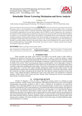
- 4. Detachable Thrust Vectoring Mechanism… The pivotal attachment of the motor to the ring is such as to allow the motor to rotate or swivel in response to the bi-directional motion of the fin. The effect is to allow the thrust of the motors to be directed by the missile control system through the fins. The propulsive forces produced by the motors are transferred through the pivots to the ring and into the missile. The thrust vector mechanism is held in place by the upward thrust of the auxiliary motors. Thus, when the main motor is subsequently ignited, the missile accelerates away from the substantially spent mechanism. While the mechanism has been described herein with reference to a particular application, it is not limited. It can have additional modifications and applications. For example, although the C ring is designed to be connected to and automatically separate from the missile’s aft end without mechanical action, various other mounting means may be employed. In addition, it is not limited to the number or type of the auxiliary motors used. Further, the mechanism is not limited to the physical nexus between the fins or other control surfaces and the motors. Where V-clips are used, they may be pivotally attached to the motors to provide a variable linkage ratio between the fins and the motors. Besides, this technique is not limited to use with aeronautical vehicles only applied to nautical vehicles as well. 4.1. Advantages Increases range. Conserves main motor fuel. High efficiency and low cost. Reduces initial missile launch signature. Provides effective steerage at low speeds. Disposable mechanism and thereby reduces weight. Fig.2. 3D model. www.theijes.com The IJES Page 4
- 5. Detachable Thrust Vectoring Mechanism… V. ANALYSIS 5.1. Stress Analysis Stress analysis was carried out on the designed model and the principal stresses, von-mises stresses, displacements and deformations were find out. Table.1.Mesh details ENTITY Nodes Elements SIZE 8845 26844 Table.2.Element type CONNECTIVITY TE4 STATISTICS 26844(100.00%) Table.3.Material properties Material Young's modulus Poisson's ratio STEEL S 97 2e+011N/m2 0.233 Density Coefficient of thermal expansion Yield strength 7860 kg/m3 1.17e-005 /K 2.5e+008N /m2 5.2. Structural Computation Number of nodes : 8845 2684 Number of elements : 4 2653 Number of D.O.F. : 5 Number of Contact relations : 0 Number of Kinematic relations : 0 5.3. Restraint computation Name : Restraints.1 Number of S.P.C : 135 5.4. Load computation Name : Loads.1 Applied load resultant : Fx = -2 . Fy = -1 . Fz = -8 . Mx = -3 . My = 4 . Mz = 1 . www.theijes.com 280e011 877e008 447e012 853e013 392e012 713e012 The IJES N N N Nm Nm Nm Page 5
- 6. Detachable Thrust Vectoring Mechanism… 5.5. Stiffness Computation Number of lines : 26535 Number of coefficients : 449205 Number of blocks : 1 Maximum number of coefficients per bloc : 449205 Total matrix size : 5.24 Mb 5.6. Singularity Computation Restraint: Restraints. 1 Number of local singularities Number of singularities in translation Number of singularities in rotation Generated constraint type : : : : 0 0 0 MPC 5.7. Constraint Computation Restraint: Restraints. 1 Number of constraints : 135 Number of coefficients :0 Number of factorized constraints Number of coefficients : 135 :0 Number of deferred constraints :0 5.8. Factorized Computation Method Number of factorized degrees : : SPARSE 26400 Number of supernodes : 1801 Number of overhead indices Number of coefficients : : 100890 2253585 Maximum front width : 348 Maximum front size Size of the factorized matrix (Mb) : : 60726 17.1935 Number of blocks : 3 Number of Mflops for factorization Number of Mflops for solve : : 3.068e+002 9.146e+000 Minimum relative pivot : 2.894e-004 Table.5.Minimum pivot Value Node x (mm) y (mm) z (mm) 2.2847e +007 www.theijes.com Dof Tx 2627 1.1071e +001 5.7592e +001 1.4127e +001 The IJES Page 6
- 7. Detachable Thrust Vectoring Mechanism… 2.5892e +007 Tx 7620 1.6771e +001 1.6683e +002 5.0000e +000 2.6740e +007 Tz 5680 8.2134e -002 1.1183e +002 1.6000e +001 2.6851e +007 Ty 7620 1.6771e +001 1.6683e +002 5.0000e +000 2.9262e +007 Tz 5615 9.7231e +000 1.2652e +002 1.2707e +001 2.9890e +007 Tz 7620 1.6771e +001 1.6683e +002 5.0000e +000 2.9937e +007 Tz 1277 5.4678e +001 4.8151e +001 1.1670e +000 3.2343e +007 Tz 447 9.8499e +000 2.9748e +001 1.6630e +001 3.2748e +007 Ty 8521 5.3952e -002 2.7405e +001 3.0877e +001 Table.6.Maximum pivot Value Dof Node x (mm) y (mm) z (mm) 1.6548 e+007 Tz 2627 1.1071 e+001 5.7592 e+001 1.4127 e+001 2.1179 e+011 Tz 2433 2.4948 e+001 7.4564 e+000 1.9445 e+001 Table.7. Translational pivot distribution Value Percentage 10.E7 --> 10.E8 10.E8 --> 10.E9 3.4788e+001 10.E9 --> 10.E10 4.8182e+001 10.E10 --> 10.E11 1.4860e+001 10.E11 --> 10.E12 www.theijes.com 1.8826e+000 2.8788e-001 The IJES Page 7
- 8. Detachable Thrust Vectoring Mechanism… 5.9. Direct Method Computation Name: Static Case Solution.1 Restraint: Restraints.1 Load: Loads.1 Strain Energy : 1.421e-024 J Table.8.Equlibrium Compo -nents Applied Forces Reac -tions Residual Relative Magnitude Error Fx (N) 2.2805e 2.2805e 4.9517e- 2.9116e- -011 022 013 1.8771e 3.3186e- 1.9514e- -011 Fy (N) 1.8771e -008 -008 Fz (N) 8.4467e 8.4467e -012 -012 Mx (Nm) 3.8533e Mz (Nm) www.theijes.com 4.3920e 1.7132e -012 2.1443e- 1.2609e013 022 3.8533e -013 -013 My (Nm) 012 021 3.6134e- 8.4037e014 023 4.3920e 4.1378e- 9.6231e- 023 014 1.2192e- 2.8355e- 022 013 -012 -012 1.7132e -012 The IJES Page 8
- 9. Detachable Thrust Vectoring Mechanism… Fig.3.Von Misses Stress for Nodal Values 1&2. Fig.4.Displacements Fig.5.Displacements. Fig.6.Principal Stresses. VI. CONCLUSION The Detachable Thrust Vectoring Mechanism will conserves the main motor fuel, reduces the initial missile launch signature and effectively increases its range. The method also provides a low cost, disposable mechanism for converting a missile designed for high speed (air-to-air) launches to one adapted for low www.theijes.com The IJES Page 9
- 10. Detachable Thrust Vectoring Mechanism… speed(surface) launches. That is, by the use of this technique the existing missiles may be inexpensively retrofit to provide thrust vector control. The model was drawn in CatiaV5 and the stress analysis was carried out in Ansys. With this the principal stresses, von-mises stresses, deformations and displacements on the model were analysed. REFERENCES [1] [2] [3] [4] [5] [6] [7] [8] [9] A. Seifert, T. Rapoport, I. Fono, K Cohen, “Closed-loop Vectoring Control of a Turbulent Jet using Periodic Excitation” 1 st AIAA Flow Control Conference, Saint Louis, MO; UNIITED ; 24-26 June 2002. Aleksander Kural, Nicolas Leveque, Chris Welch, Piotr Wolanski “Design of an Ion Thruster Movable Grid Thrust Vectoring System”, July 2004. David G. Fearn, QinetiQ Farnborough, “Ion Thruster Thrust Vectoring Requirements and Techniques” International Electric Propulsion Conference, Pasadena, CA, October, 2011. E. Glenn Case, “Preliminary Design of a Hybrid Rocket Liquid Injection Thrust Vector Control System” IV, Purdue University, West Lafayette, IN, 47907. F.S. Alvi, P.J. Strykowski, A. Krothapalli, D.J. Forliti, “Vectoring Thrust in Multiaxes Using Confined Shear Layers” Journal of Fluids Engineering, Volume 122, Issue 1,3. George W. Hawk, Lewis H. Geyer, Alfred J. Mastrople, Kenneth D. Garnjost “Secondary Injection Thrust Vector Control”, United States Patent,1972. Martin J. Brenner, “Aeroservoelastic Modeling and Validation of a Thrust-Vectoring F/A-18 Aircraft”, NASA Technical Paper 3647, Septamber 1996. Michael Bolitho, Jamey D. Jacob, “Thrust Vectoring Flow Control Using Plasma Synthetic Jet Actuators”, 46 th AIAA Aerospace Sciences Meeting. P. J. Yagle, D.N. Miller, K.B. Ginnand, J.W. Hamstra “Demonstration of Fluidic Throat Skewing for Thrust Vectoring in Structurally Fixed Nozzles”, Journal of Engineering for Gas Turbines and Power, July 2001, Volume 123, Issue 3,502. www.theijes.com The IJES Page 10