Application Note—Compressed Air

The energy costs related to compressed air represent between 10 to 15% of the electricity bill of the average industrial consumer. This application guide gives an overview of technical and organizational solutions that will maximize the energetic efficiency of the system. Implementation of these measures can save up to 25% of the systems’ energy consumption. A first important question to ask is whether compressed air is the best available technique for the required solutions. In many cases other, more energy efficient technologies are available. If compressed air is the best available technique, several actions can improve the energy efficiency of the system: • Any design of a new system or the assessment of an existing system should start with an analysis of the needs. If the air demand is variable, an energy efficient control system for dealing with those load variations should be chosen. • The compressed air distribution network should be carefully designed and maintained. In particular, reducing air leaks can have a significant positive influence on the energy efficiency of the system. • For thermodynamic reasons, reducing the inlet air temperature and the outlet air pressure has an important influence on the systems’ energy efficiency. • If air dryers are required for avoiding equipment degradation, they should be carefully selected, based on their energy efficiency. • In some cases, the heat losses of a compressed air system can be recovered for heating applications. Finally, maximizing the energy efficiency of a compressed air system is not a one-time action. Continuous monitoring of key parts, and adjusting them when necessary, is indispensable.

Recomendados
Recomendados
Mais conteúdo relacionado
Mais procurados
Mais procurados (20)
Destaque
Destaque (20)
Semelhante a Application Note—Compressed Air
Semelhante a Application Note—Compressed Air (20)
Mais de Leonardo ENERGY
Mais de Leonardo ENERGY (20)
Último
Último (20)
Application Note—Compressed Air
- 1. European Copper Institute APPLICATION NOTE COMPRESSED AIR Jean Timmermans, Laborelec November 2011 ECI Publication No. Cu0116 Available from www.leonardo-energy.org /node/1712
- 2. Publication No Cu0116 Issue Date: November 2011 Page i Document Issue Control Sheet Document Title: Application Note—Compressed Air Publication No.: Cu0116 Issue: 02 Release: November 2011 Author(s): Jean Timmermans, Laborelec Reviewer(s): Bruno De Wachter Document History Issue Date Purpose 1 February 2007 Initial publication 2 November 2011 Upgrade for adoption into the Good Practice Guide 3 Disclaimer While this publication has been prepared with care, European Copper Institute and other contributors provide no warranty with regards to the content and shall not be liable for any direct, incidental, or consequential damages that may result from the use of the information or the data contained. Copyright© European Copper Institute. Reproduction is authorized providing the material is unabridged and the source is acknowledged.
- 3. Publication No Cu0116 Issue Date: November 2011 Page ii CONTENTS Summary ........................................................................................................................................................ 1 Introduction.................................................................................................................................................... 2 The cost of compressed air.....................................................................................................................................2 The compressor choice...........................................................................................................................................3 Energy saving measures.................................................................................................................................. 4 Avoiding inappropriate use of compressed air.......................................................................................................4 Dealing with variable demands ..............................................................................................................................4 Load/unload control.................................................................................................................................4 Storage .....................................................................................................................................................4 Several compressors in cascade...............................................................................................................4 System Master Controls ...........................................................................................................................6 Variable Speed drives...............................................................................................................................6 An energy-efficient distribution network ...............................................................................................................7 Avoiding leaks.........................................................................................................................................................7 Reducing the air inlet temperature ........................................................................................................................8 Reducing the outlet pressure .................................................................................................................................9 Limiting the energy consumption of dryers .........................................................................................................10 Heat recovery systems .........................................................................................................................................10 Conclusion .................................................................................................................................................... 12 References.................................................................................................................................................... 12
- 4. Publication No Cu0116 Issue Date: November 2011 Page 1 SUMMARY The energy costs related to compressed air represent between 10 to 15% of the electricity bill of the average industrial consumer. This application guide gives an overview of technical and organizational solutions that will maximize the energetic efficiency of the system. Implementation of these measures can save up to 25% of the systems’ energy consumption. A first important question to ask is whether compressed air is the best available technique for the required solutions. In many cases other, more energy efficient technologies are available. If compressed air is the best available technique, several actions can improve the energy efficiency of the system: Any design of a new system or the assessment of an existing system should start with an analysis of the needs. If the air demand is variable, an energy efficient control system for dealing with those load variations should be chosen. The compressed air distribution network should be carefully designed and maintained. In particular, reducing air leaks can have a significant positive influence on the energy efficiency of the system. For thermodynamic reasons, reducing the inlet air temperature and the outlet air pressure has an important influence on the systems’ energy efficiency. If air dryers are required for avoiding equipment degradation, they should be carefully selected, based on their energy efficiency. In some cases, the heat losses of a compressed air system can be recovered for heating applications. Finally, maximizing the energy efficiency of a compressed air system is not a one-time action. Continuous monitoring of key parts, and adjusting them when necessary, is indispensable.
- 5. Publication No Cu0116 Issue Date: November 2011 Page 2 INTRODUCTION THE COST OF COMPRESSED AIR Compressed air is a well-known and proven technology and has many applications in industry. It is used in extrusion processes, paint spraying, blow moulding and in more generic processes such as vacuum production, manipulation processes, and for controlling and transportation applications. Nevertheless, delivering compressed air to a manufacturing facility is an expensive operation. Delivery requires costly equipment that consumes significant amounts of electricity and requires frequent maintenance. The following table shows the different cost components of compressed air: Absolute price: Production 4.45 … 8.90 €/kNm 3 Driers 0.45 … 1.60 €/kNm 3 Investment 0.75 … 1.00 €/kNm 3 Maintenance 0.60 … 1.00 €/kNm 3 Supplementary costs Distribution 0.25 … 0.75 €/kNm 3 Leaks 0.75 … 2.25 €/kNm 3 Total Cost 7.25 … 5.50 €/kNm 3 The energy consumption represents between 60 and 90% of the total cost related to compressed air and is far more dominant than the investment and maintenance cost. Figure 1: Cost breakdown for compressed air production. energy 76% maintenance 11% investment 12% water 1%
- 6. Publication No Cu0116 Issue Date: November 2011 Page 3 THE COMPRESSOR CHOICE Three main types of compressors are used for the production of compressed air: Reciprocating or piston compressors Rotary screw compressors Rotary centrifugal compressors Reciprocating compressors are positive displacement machines. They increase the pressure of the air by reducing its volume. More precisely, they take in successive volumes of air, confine them in a closed cylindrical space, and elevate them to a higher pressure by a compression piston. Piston compressors are available in a single-stage or multi-stage configuration, depending on the pressure level. They have high energy efficiency (75%), but the piston valves require considerable maintenance. Rotary screw compressors are also positive displacement compressors. They consist of two rotors inside a casing that compress the air internally. Since there are no valves, maintenance is less intensive. The rotors are oil cooled, and this oil also seals the internal clearances. The oil is, in its, turn cooled by air or by water. The efficiency of this type of compressor is approximately 71%. Oil free screw compressors utilize specially designed air ends to compress air without oil in the compression chamber yielding true oil free air. Their efficiency is around 73% The centrifugal compressor is a dynamic compressor, meaning that its working principle is based on a transfer of energy from a rotating impeller to the air. An impeller rotates inside a volute casing. The air is taken in at the centre and is pressed against the casing by the angular momentum of the impeller. This produces a high pressure discharge at the end of the volute. These types of compressors are designed for higher capacity as their flow is continuous. They have an energy efficiency of approximately 75%.
- 7. Publication No Cu0116 Issue Date: November 2011 Page 4 ENERGY SAVING MEASURES AVOIDING INAPPROPRIATE USE OF COMPRESSED AIR Compressed air can hardly be called an efficient energy carrier. Of the total energy consumption for the production of compressed air, only 10% is converted into useful energy and 90% is converted into heat. However, since compressed air is also clean, readily available, and simple to use, it is often chosen for applications for which it is not the most cost efficient option. Users should always consider more cost-effective forms of power before considering compressed air. Examples of potentially inappropriate uses of compressed air include open blowing, aspirating, vacuum generation, and cabinet cooling. Potential alternatives are blowers, ventilators, and vacuum pumps. The use of electrical tooling instead of pneumatic tooling can also be considered, as this will in most cases result in energy savings of approximately 90%. DEALING WITH VARIABLE DEMANDS Air demand changes continuously in an industrial factory. System controls need to match air supply with demand and are of great importance to energy efficiency. LOAD/UNLOAD CONTROL The most basic concept is the load/unload control. The system pressure is monitored and unloads the compressor when the discharge pressure is adequate. When the system pressure reaches a predetermined minimum level, the compressor is loaded again, and pressure will rise. Since the motor runs continuously, an unloaded rotary screw compressor will consume 15 to 35% of full load power, while delivering no useful work. When the demand is volatile, there are many switches between load and unload, resulting in a consumption during unload periods of 40% or even higher. STORAGE Load peaks and dips can be levelled off by short-term storage. Receiver tanks can store compressed air temporary without significant pressure drops. Lowering demand peaks has an important advantage in that a smaller compressor can be chosen to achieve the same result. The time this compressor will run unloaded will be reduced, resulting in significant energy savings. SEVERAL COMPRESSORS IN CASCADE When the air demand varies substantially, the unload time of the compressor can become very high. It can be reduced by installing several compressors of smaller nominal capacities in cascade. The cascade concept in itself does not result in energy savings as long as the lagging compressors continue to run unloaded, drawing significant power. However, most compressors have a ‘sleep’ or ‘automatic’ mode in which they turn off after running unloaded for 5 or 10 minutes. Consequently, the cascade mode will start to save energy if the load has strong variations over periods of more than 5 to 10 minutes. The following simulation illustrates the effect of staging multiple compressors. Suppose we have a linear growing air demand resulting in following consumption profile (from 5 to 27 Nm³/min):
- 8. Publication No Cu0116 Issue Date: November 2011 Page 5 Figure 2: Demand profile. Three compressors with the same nominal capacity (10 Nm 3 /min) work in a load/unload regime in order to deliver the required compressed air. The compressors are staged by setting the activation pressure of the baseload compressor a bit higher than the activation pressures of the lagging computers: Compressor Load pressure (pLow) Unload pressure (pHigh) Comp. 1 6.5 bar 7 bar Comp. 2 6.25 bar 6.75 bar Comp. 3 6 bar 6.5 bar The produced flow (bottom toothed line) and resulting air pressure (upper toothed line) look as follows: Figure 3: Three compressors in cascade: resulting air pressure and produced flow. 4.25 4.75 5.25 5.75 6.25 6.75 7.25 0 60 120 180 240 300 360 420 480 540 600 660 720 780 840 900 960 1020 1080 1140 1200 1260 1320 1380 1440 1500 1560 1620 1680 1740 1800 seconds Pressure(bar(e)) 0 10 20 30 40 50 60 Flow(m³/min) 4.25 4.75 5.25 5.75 6.25 6.75 7.25 0 60 120 180 240 300 360 420 480 540 600 660 720 780 840 900 960 1020 1080 1140 1200 1260 1320 1380 1440 1500 1560 1620 1680 1740 1800 seconds Pressure(bar(e)) 0 10 20 30 40 50 60 Flow(m³/min)
- 9. Publication No Cu0116 Issue Date: November 2011 Page 6 This simulation shows that the cascade concept in the pressure set points, which is needed to prioritize the compressors, leads to a significant variation in the system’s pressure. Moreover, the unload period is still fairly high, resulting in a specific average consumption (113 Wh/Nm 3 ) that is still fairly high as well. SYSTEM MASTER CONTROLS The disadvantages of a simple cascade mode can be avoided with a system master control. It consists of a central control system (Master Control) for the entire compressed air network and its compressor fleet. This network can extend over several compressor rooms and several buildings of the site. The compressors can be of different brands and types. If configured properly, the Master Control will determine the most energy-efficient response to every change of demand. At each moment, it will make the best selection of compressors to fulfil the concerned demand, minimizing the number of compressors running in unload regime. Adding such a centralized control system to the previous example results in the following system pressure (upper toothed line) and production flow (bottom toothed line): Figure 4: System Master Control: resulting air pressure and produced flow. The resulting discharge pressure has lower variability than in the previous example, resulting in a more stable system pressure and a lower specific consumption (111 Wh/Nm 3 ). VARIABLE SPEED DRIVES Rotary compressors can be equipped with integrated variable frequency drives (VSDs) to further reduce losses due to load variations. Such a VSD will raise the compressor speed when the discharge pressure drops and vice versa. With this type of control, the compressor discharge pressure can be held within narrow limits, resulting in a lower average discharge pressure. There is no (or little) unload consumption. Measurements at Laborelec show significant energy savings are possible and are bigger as the variability of the demand profile raises. More specifically, short-term variations will be taken care of more efficiently with a VSD than with a cascade or system master control alone. Savings up to 40% are not exceptional. Integration of a VSD compressor in a central control system will improve the stability of the system pressure and avoid unload running of the base compressors. This is shown in following simulation: 4.25 4.75 5.25 5.75 6.25 6.75 7.25 0 60 120 180 240 300 360 420 480 540 600 660 720 780 840 900 960 1020 1080 1140 1200 1260 1320 1380 1440 1500 1560 1620 1680 1740 1800 seconds Pressure(bar(e)) 0 10 20 30 40 50 60 Flow(m³/min)
- 10. Publication No Cu0116 Issue Date: November 2011 Page 7 Figure 5: System Master Control with VSD on the base compressor: resulting air pressure and produced flow. In this case, a variable speed compressor with a nominal capacity of 15 Nm 3 /min is added to the previous system. By doing so, the specific consumption is reduced to 103 Wh/Nm 3 . To obtain the best results, the capacity of the variable speed compressor should be higher than the flow variation. If not, so called ‘regulation gaps’ will occur. For these certain ranges of demand, the regulation system will fall short of an optimal answer and one or more compressors will run unloaded. AN ENERGY-EFFICIENT DISTRIBUTION NETWORK The piping network that distributes the produced compressed air to the application also merits attention. Any type of obstruction, restriction, or roughness in the system will cause resistance to air flow and cause a pressure drop, resulting in a loss of energy efficiency. Using ring-shaped networks will result in lower pressure drops compared to antenna shaped networks. The intake air is filtered since the air of the compressor needs to be free of particles, dirt, and raindrops. Added to that, air/lubricant separators, after-coolers, moisture separators, and dryers are often integrated at the supply side of the system. Each piece of this equipment causes a significant pressure drop. These components need regular maintenance and cleaning to reduce those discharge losses. A reduction of 0.05 bars of discharge losses will result in an energy saving of 1%. The design of the system is equally important. The intake air path needs to be as short as possible, installed with large sections and minimal sharp turns, in order to avoid pressure drops. Specifications for regulators and lubricators need to have the best performance characteristics at the lowest pressure differential. These components must be sized based upon the actual rate of flow, which can be different from the average rate of flow over a longer period. AVOIDING LEAKS Air leaks often represent a significant source of wasted energy. The average industrial compressed air system running without proper maintenance will likely have a leak rate of 20% or higher. Proactive leak detection and repair can reduce leaks to less than 10% of the compressor output. 4.25 4.75 5.25 5.75 6.25 6.75 7.25 0 60 120 180 240 300 360 420 480 540 600 660 720 780 840 900 960 1020 1080 1140 1200 1260 1320 1380 1440 1500 1560 1620 1680 1740 1800 seconds Pressure(bar(e)) 0 10 20 30 40 50 60 Flow(m³/min)
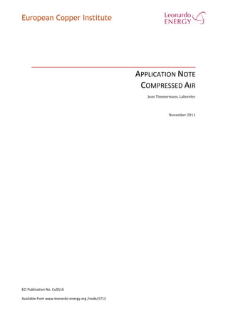
- 11. Publication No Cu0116 Issue Date: November 2011 Page 8 Figure 6: Annual cost of air leakage. An easy way to estimate the leak rate is to let the system run without any load and determine the power the compressor is still delivering. More precisely, if all air users in the system are turned off, the leakage can be estimated by dividing the on-load time by the total cycle time of the compressor. While leakages can come from any part of the system, the most common problem areas are: Couplings, hoses, tubes, and fittings Pressure regulators Open condensate traps and shut-off traps Non-operating equipment Air leaks are almost impossible to see, and cannot always be heard. This means that other methods must be used to locate them. The best way to detect leaks is to use an ultrasonic acoustic detector, which can recognize the high-frequency hissing sounds associated with air leaks. A time-efficient and systematic way to reduce leakage is the leak-tag method. With this method, leaks that are identified during the execution of operational tasks or maintenance actions are marked with a two-part tag. One part stays at the leak and the other part is turned to the maintenance department, identifying the location, size, and description of the leak to be repaired. REDUCING THE AIR INLET TEMPERATURE For the compression of a perfect gas, the mechanical power can be calculated as follows: ( ) [( ) ( ) ] With ( ) ( ) And Pad = Mechanical power Annual cost of an air leakage 0 500 1000 1500 2000 2500 3000 3500 4000 0 0,5 1 1,5 2 2,5 3 diameter leakage (mm) cost(EURO) 4 bar 6 bar 8 bar 10 bar
- 12. Publication No Cu0116 Issue Date: November 2011 Page 9 M = Air mass flow R = Ideal gas constant ϒ = 1.4 ηad = Adiabatic efficiency T1 = Air inlet temperature p1 = Air inlet pressure p2 = Air outlet pressure The thermodynamic formula shows that a higher inlet temperatures result in a higher mechanical power that is needed to drive the compressor. The energy consumption rises by about 0.3% per degree Celsius. Well- designed installations use outside air, and have their air intake on the north side of the building, far away from heat sources like steam conducts, burners, ovens, et cetera. This can result in a reduction of the inlet temperature of 10 °C, saving about 3.5% of energy. REDUCING THE OUTLET PRESSURE Air that is compressed to a higher pressure than necessary is a waste of energy. The thermodynamic formula in the previous paragraph shows that higher outlet pressure demands higher compressor power for the same amount of compressed air. Often, the compressed air consumer that needs the highest pressure determines the general outlet pressure of the complete system. In many cases, it will be more efficient to split the network in a low pressure net and a high pressure net, which are each fed by a different compressor. A calculation example shows the saving potential: A shop requires compressed air at 11 bar and at 6 bar. Each has a required flow of 10m 3 /s. To provide the 20 m 3 /s at 11 bar, a mechanical power of 10,162 kW is needed. In a separated system, the high-pressure net needs 5,081 kW and the low pressure net 3,720 kW, resulting in an energy saving of 13.4%. If the distribution piping system causes an excessive pressure drop, this will also result in a higher required outlet pressure of the compressor. A properly designed system should have a pressure loss of much less than 10% of the compressor discharge pressure. Raising the compressor discharge pressure also results in another energy penalty: it will increase the consumption for every kind of unregulated usage, including leaks, open blowing, et cetera. Following graph shows the impact of reducing the outlet pressure on the specific consumption of compressed air:
- 13. Publication No Cu0116 Issue Date: November 2011 Page 10 Figure 7: Influence of system pressure on compressed air cost LIMITING THE ENERGY CONSUMPTION OF DRYERS The compressed air that is leaving the compressor is normally warmer than the ambient air and fully saturated with moisture. As the air cools down in the pipes, the moisture will condense. This could lead to pipe corrosion and contamination at the point of end use of the compressed air. Air dryers avoid excessive condensation by suppressing the dew point. However, those dryers typically cause a pressure drop of 3 to 5 psi, and even higher if they are undersized. This pressure drop results in a significant energy loss for the system. For this reason, compressed air should only be dried to the degree that is needed for the proper maintenance and operation of the system, and appropriately sized dryers should be used. Different types of compressed air dryers have different operating characteristics and degrees of dew point suppression. The selection of a compressed air dryer should be based upon the required dew point and the estimated efficiency loss. Refrigerant-type dryers are the most common and suppress the dew point to 2 °C, which is acceptable for many applications. Some end use applications require very dry air, such as compressed air distribution systems where pipes are exposed to winter conditions. In such a case, drying the air to dew points below ambient conditions is necessary to prevent ice build-up. Twin tower desiccant-type dryers are the most common for these kinds of application. They typically have rated dew points of around -20 °C. The regeneration of the desiccant is carried out either by purged air or by heat. Regenerative desiccant dryers use the heat of compressor cooling circuits for desiccant regeneration, improving the energy efficiency. HEAT RECOVERY SYSTEMS A significant portion of the mechanical power is converted into heat. A large part of this heat can be recovered in the form of hot air or hot water. Hot air can be used for: Influence of system pressure on compressed air cost 0 20 40 60 80 100 120 140 160 4 5 6 7 8 9 10 pressure (bar) cost(%) leakage air used air
- 14. Publication No Cu0116 Issue Date: November 2011 Page 11 Direct heating of neighbouring rooms Preheating of the combustion air of boilers Hot air for drying applications Hot water can be produced at a temperature of 90 °C in a closed circuit. Possible applications are: The heating of sanitary water via a heat exchanger Central building heating Direct use of the cooling water as feed water for steam boilers. The amount of heat that can be recovered depends on the air demand and the type of control system. It is obvious that variable speed driven compressors will have a lower heat recovery potential than load/unload compressor control.
- 15. Publication No Cu0116 Issue Date: November 2011 Page 12 CONCLUSIONS Designing, improving, and maintaining a compressed air network for maximum performance requires a system’s approach. The interaction between supply and demand should be assessed as well as individual components. The following elements can be part of an action plan to maximize overall energy efficiency: 1) When designing a new installation, first analyze what the best energy carrier is for the required applications. Is compressed air the most appropriate? 2) It can be equally useful to re-analyze the situation for existing installations. Exchanging the compressed air network by another type of system might be a profitable investment. 3) Once compressed air is chosen as the preferred energy carrier, carefully analyze the needs. Bear in mind that for thermodynamic reasons, reducing the outlet pressure of the system will significantly increase its energy efficiency. 4) Carefully analyze the operating data and/or the expected working regimen. The control system can be designed or improved based on this analysis. The method selected to cope with demand variations will have a particularly important influence on the energy efficiency of the system. 5) Check for opportunities at component level. The choice of the compressor type can have a substantial influence on the energy efficiency of the system. 6) The compressed air distribution network should be carefully designed and maintained. Reducing the air leaks in the network and reducing the air inlet temperature are two measures that can significantly improve the systems’ energy efficiency. 7) Compressed air should be dried only to the level that is actually necessary for proper maintenance and operation. The type and dimension of air dryers should be selected with care. 8) Consider the recovery of compressor heat losses in the form of hot water or hot air. 9) Monitor the results of improvement actions. 10) Continue to monitor and optimize the system; maximizing the energy efficiency of a compressed air system is not temporary project. REFERENCES [1] E. M. Talbott, Compressed Air Systems (second edition), The Fairmont press Inc., Georgia (USA), 1992. [2] J.P. Rollins (Compressed Air and Gas Institute), Compressed Air and Gas Handbook, Prentice Hall PTR, New Jersey (USA), 1989. [3] http://www.energystar.gov/, accessed in December 2006