SlideShare a Scribd company logo
1 of 34
Digital Communication System
   7.1 and 7.2 (part)
   Source: sequence of digits
   Multiplexer: FDMA, TDMA, CDMA…
   Line Coder
    – Code chosen for use within a communications system for
      transmission purposes.
    – Baseband transmission
    – Twisted wire, cable, fiber communications
   Regenerative repeator
    – Detect incoming signals and regenerate new clean pulses


          EE 541/451 Fall 2006
Line coding and decoding


EE 541/451 Fall 2006
Signal element versus data element


 EE 541/451 Fall 2006
Data Rate Vs. Signal Rate
   Data rate: the number of data elements (bits) sent in 1s (bps).
    It’s also called the bit rate
   Signal rate: the number of signal elements sent in 1s (baud).
    It’s also called the pulse rate, the modulation rate, or the baud
    rate.
   We wish to:
    –   increase the data rate (increase the speed of transmission)
    –   decrease the signal rate (decrease the bandwidth requirement)
    –   worst case, best case, and average case of r
    –   N bit rate
    –   c is a constant that depends on different line codes.
    –   S = c * N / r baud

          EE 541/451 Fall 2006
Example
•   A signal is carrying data in which one data element is encoded
    as one signal element ( r = 1). If the bit rate is 100 kbps, what is
    the average value of the baud rate if c is between 0 and 1?
   Solution
    – We assume that the average value of c is 1/2 . The baud rate is then


•   Although the actual bandwidth of a digital signal is infinite, the
    effective bandwidth is finite.
•   What is the relationship between baud rate, bit rate, and the
    required bandwidth?

          EE 541/451 Fall 2006
Self-synchronization
   Receiver Setting the clock matching the sender’s
   Effect of lack of synchronization


          EE 541/451 Fall 2006
Example
•   In a digital transmission, the receiver clock is 0.1 percent faster
    than the sender clock. How many extra bits per second does the
    receiver receive if the data rate is 1 kbps? How many if the data
    rate is 1 Mbps?
   Solution
    – At 1 kbps, the receiver receives 1001 bps instead of 1000 bps.


    – At 1 Mbps, the receiver receives 1,001,000 bps instead of
      1,000,000 bps.


          EE 541/451 Fall 2006
Other properties
   DC components
   Transmission bandwidth
   Power efficiency
   Error detection and correction capability
   Favorable power spectral density
   Adequate timing content
   Transparency


          EE 541/451 Fall 2006
Line coding schemes


EE 541/451 Fall 2006
Unipolar NRZ scheme


EE 541/451 Fall 2006
Polar NRZ-L and NRZ-I schemes
•   In NRZ-L, the level of the voltage determines the value of the bit.
    RS232.
•   In NRZ-I, the inversion or the lack of inversion determines the value
    of the bit. USB, Compact CD, and Fast-Ethernet.
•   NRZ-L and NRZ-I both have an average signal rate of N/2 Bd.
   NRZ-L and NRZ-I both have a DC component problem.


          EE 541/451 Fall 2006
RZ scheme
   Return to zero
   Self clocking


          EE 541/451 Fall 2006
Polar biphase: Manchester and differential Manchester schemes
    In Manchester and differential Manchester encoding, the transition at the
     middle of the bit is used for synchronization.
    The minimum bandwidth of Manchester and differential Manchester is 2
     times that of NRZ. 802.3 token bus and 802.4 Ethernet


            EE 541/451 Fall 2006
Bipolar schemes: AMI and pseudoternary
   In bipolar encoding, we use three levels: positive, zero, and negative.
   Pseudoternary:
     – 1 represented by absence of line signal
     – 0 represented by alternating positive and negative
   DS1, E1


           EE 541/451 Fall 2006
Basic steps for spectrum analysis
   Figure 7.3, 7.4
     – Basic pulse function and its spectrum P(w)
        x   For example, rect. function is sinc
     – Input x is the pulse function with different amplitude as
       figure 7.3c
        x   Carry different information with sign and amplitude
        x   Auto correlation is the spectrum of Sx(w)
                       Tb
            Rn = lim
                  T →∞ T
                            ∑a a
                              k
                                    k   k +n


                       1     ∞
                                                   1        ∞
                                                                           
                 ∑Re
            S x ( w) =
                       Tb   n =−∞
                                    n
                                        − jnwTb
                                                  =  R0 + 2∑ Rn e − jnwTb 
                                                   Tb      n =1           
     – Overall spectrum
                                                  2
              S y ( w) = P ( w) S y ( w)

            EE 541/451 Fall 2006
Line coding schemes

                       10 points in the finals


EE 541/451 Fall 2006
NRZ
   R0=1, Rn=0, n>0
   Figure 7.5 pulse width Tb/2
   P(w)=Tb sinc(wTb/2)
   Bandwidth Rb for pulse width Tb


          EE 541/451 Fall 2006
RZ scheme
   DC Nulling                                               ωT
                                                        sin 2
   Split phase                  r ( t ) ↔ R( ω ) = T         4
                                                           ωT
   Figure 7.6(a)                                           4


          EE 541/451 Fall 2006
Polar biphase: Manchester and differential Manchester schemes
    In Manchester and differential Manchester encoding, the transition at the
     middle of the bit is used for synchronization.
    The minimum bandwidth of Manchester and differential Manchester is 2
     times that of NRZ. 802.3 token bus and 802.4 Ethernet


            EE 541/451 Fall 2006
Bipolar schemes: AMI and pseudoternary
   R0=1/2, R1=-1/4, Rn=0,n>1, page 307 for reasons
   Figure 7.8
                        2
               P ( w)                           Tb          wT    2  wTb 
    S y ( w) =              [ 1 − cos wTb ] =      sin c 2  b     sin  2 
                2Tb                             4           4            

   Reason: the phase changes slower


            EE 541/451 Fall 2006
Multilevel: 2B1Q scheme
   NRZ with
amplitude
representing more
bits


         EE 541/451 Fall 2006
HDB3 (High Density Bipolar of order 3 code)
   Replacing series of four bits that are to equal to "0" with a code word
    "000V" or "B00V", where "V" is a pulse that violates the AMI law of
    alternate polarity and is rectangular or some other shape. The rules for using
    "000V" or "B00V" are as follows:

     – "B00V" is used when up to the previous pulse, the coded signal presents
       a DC component that is not null (the number of positive pulses is not
       compensated for by the number of negative pulses).
     – "000V" is used under the same conditions as above when up to the
       previous pulse the DC component is null.
     – The pulse "B" ("B" for balancing), which respects the AMI alternancy
       rule, has positive or negative polarity, ensuring that two successive V
       pulses will have different polarity.


   Used in E1

           EE 541/451 Fall 2006
HDB3
   The timing information is preserved by embedding it in the line
    signal even when long sequences of zeros are transmitted,
    which allows the clock to be recovered properly on reception.
   The DC component of a signal that is coded in HDB3 is null.


          EE 541/451 Fall 2006
Bipolar 8-Zero Substitution (B8ZS)
   Adds synchronization for long strings of 0s
   North American system
   Same working principle as AMI except for eight consecutive 0s
    10000000001  +000+-0-+01               in general   00000000000V(-V)0(-V)V
            1         0        0        0   0     0          0       0   0   0   1
Amplitude


                                                                                     Time


                            Violation                    Violation

   Evaluation
      – Adds synchronization without changing the DC balance
      – Error detection possible
   Used in T1/DS1
                EE 541/451 Fall 2006
Coded Mark Inversion (CMI)
   Another modification from AMI: Binary 0 is represented by a half period of
    negative voltage followed by a half period of positive voltage
   Advantages:
     – good clock recovery and no d.c. offset
     – simple circuitry for encoder and decoder − compared with HDB3
   Disadvantages: high bandwidth


           EE 541/451 Fall 2006
Multilevel: 2B1Q scheme
   Integrated
Services
Digital
Network
ISDN


           EE 541/451 Fall 2006
mBnL schemes
•   In mBnL schemes, a pattern of m data elements is encoded as a
    pattern of n signal elements in which 2^m ≤ L^n.
•   Multilevel: 8B6T scheme, T4


          EE 541/451 Fall 2006
8B6T code table (partial)


EE 541/451 Fall 2006
Multilevel: 4D-PAM5 scheme


EE 541/451 Fall 2006
Multitransition: MLT-3 scheme


EE 541/451 Fall 2006
PSD of various line codes


EE 541/451 Fall 2006
Clock Recovery
   A timing reference signal can be extracted from the received signal by
    differentiation and full-wave rectification − provided that the signal carries
    sufficient transitions.
   This timing reference signal is then used to fine tune the frequency and phase
    of a local oscillator. The receiver clock is then derived (e.g. add a phase
    shift) from this local oscillator.


           EE 541/451 Fall 2006
Clock Recovery
   Simple Circuit


   PLL


          EE 541/451 Fall 2006
Summary of line coding schemes


                Plus HDB3 and B8ZS

   EE 541/451 Fall 2006

More Related Content

What's hot

UNIT-II -DIGITAL SYSTEM DESIGN
UNIT-II -DIGITAL SYSTEM DESIGNUNIT-II -DIGITAL SYSTEM DESIGN
UNIT-II -DIGITAL SYSTEM DESIGN
Dr.YNM
 
Vlsi lab viva question with answers
Vlsi lab viva question with answersVlsi lab viva question with answers
Vlsi lab viva question with answers
Ayesha Ambreen
 
What is 16 qam modulation
What is 16 qam modulationWhat is 16 qam modulation
What is 16 qam modulation
FOSCO Fiber Optics
 
Digital t carriers and multiplexing power point (laurens)
Digital t carriers and multiplexing power point (laurens)Digital t carriers and multiplexing power point (laurens)
Digital t carriers and multiplexing power point (laurens)
Laurens Luis Bugayong
 

What's hot (20)

Chapter 4
Chapter 4Chapter 4
Chapter 4
 
Line coding
Line codingLine coding
Line coding
 
Multipliers in VLSI
Multipliers in VLSIMultipliers in VLSI
Multipliers in VLSI
 
The IEEE 1149.1 Boundary-scan test standard
The IEEE 1149.1 Boundary-scan test standardThe IEEE 1149.1 Boundary-scan test standard
The IEEE 1149.1 Boundary-scan test standard
 
Overview of sampling
Overview of samplingOverview of sampling
Overview of sampling
 
signal and channel bandwidth
signal and channel bandwidthsignal and channel bandwidth
signal and channel bandwidth
 
Matched filter
Matched filterMatched filter
Matched filter
 
quantization
quantizationquantization
quantization
 
FM-Foster - Seeley Discriminator.pptx
FM-Foster - Seeley Discriminator.pptxFM-Foster - Seeley Discriminator.pptx
FM-Foster - Seeley Discriminator.pptx
 
UNIT-II -DIGITAL SYSTEM DESIGN
UNIT-II -DIGITAL SYSTEM DESIGNUNIT-II -DIGITAL SYSTEM DESIGN
UNIT-II -DIGITAL SYSTEM DESIGN
 
BCH Codes
BCH CodesBCH Codes
BCH Codes
 
Mod 10 synchronous counter updated
Mod 10 synchronous counter updatedMod 10 synchronous counter updated
Mod 10 synchronous counter updated
 
Delta Modulation
Delta ModulationDelta Modulation
Delta Modulation
 
Vlsi lab viva question with answers
Vlsi lab viva question with answersVlsi lab viva question with answers
Vlsi lab viva question with answers
 
Finite word length effects
Finite word length effectsFinite word length effects
Finite word length effects
 
4 bit add sub
4 bit add sub4 bit add sub
4 bit add sub
 
Introduction to DSP.ppt
Introduction to DSP.pptIntroduction to DSP.ppt
Introduction to DSP.ppt
 
What is 16 qam modulation
What is 16 qam modulationWhat is 16 qam modulation
What is 16 qam modulation
 
Eye diagram in Communication
Eye diagram in CommunicationEye diagram in Communication
Eye diagram in Communication
 
Digital t carriers and multiplexing power point (laurens)
Digital t carriers and multiplexing power point (laurens)Digital t carriers and multiplexing power point (laurens)
Digital t carriers and multiplexing power point (laurens)
 

Similar to Line coding

Binary to digital encoding tbs 301
Binary to digital encoding tbs 301Binary to digital encoding tbs 301
Binary to digital encoding tbs 301
Bhupesh Rawat
 
Digital modulation techniques
Digital modulation techniquesDigital modulation techniques
Digital modulation techniques
srkrishna341
 
CodingI.pdfSDFSDGSDFGSFSDFFFDFDFSDFSDFDF
CodingI.pdfSDFSDGSDFGSFSDFFFDFDFSDFSDFDFCodingI.pdfSDFSDGSDFGSFSDFFFDFDFSDFSDFDF
CodingI.pdfSDFSDGSDFGSFSDFFFDFDFSDFSDFDF
tHunh5775
 
W6_Ch5_Signal Encoding.pdf
W6_Ch5_Signal Encoding.pdfW6_Ch5_Signal Encoding.pdf
W6_Ch5_Signal Encoding.pdf
matom84405
 
Data Encoding
Data EncodingData Encoding
Data Encoding
Luka M G
 
Tsinghua visit
Tsinghua visitTsinghua visit
Tsinghua visit
wtyru1989
 

Similar to Line coding (20)

Binary to digital encoding tbs 301
Binary to digital encoding tbs 301Binary to digital encoding tbs 301
Binary to digital encoding tbs 301
 
Digital modulation techniques
Digital modulation techniquesDigital modulation techniques
Digital modulation techniques
 
Baseline Wandering
Baseline WanderingBaseline Wandering
Baseline Wandering
 
Chapter4
Chapter4Chapter4
Chapter4
 
International Journal of Engineering Inventions (IJEI)
International Journal of Engineering Inventions (IJEI)International Journal of Engineering Inventions (IJEI)
International Journal of Engineering Inventions (IJEI)
 
Modulation technology
Modulation technologyModulation technology
Modulation technology
 
CodingI.pdfSDFSDGSDFGSFSDFFFDFDFSDFSDFDF
CodingI.pdfSDFSDGSDFGSFSDFFFDFDFSDFSDFDFCodingI.pdfSDFSDGSDFGSFSDFFFDFDFSDFSDFDF
CodingI.pdfSDFSDGSDFGSFSDFFFDFDFSDFSDFDF
 
W6_Ch5_Signal Encoding.pdf
W6_Ch5_Signal Encoding.pdfW6_Ch5_Signal Encoding.pdf
W6_Ch5_Signal Encoding.pdf
 
DC_PPT.pptx
DC_PPT.pptxDC_PPT.pptx
DC_PPT.pptx
 
Ch04
Ch04Ch04
Ch04
 
Dcn aasignment
Dcn aasignmentDcn aasignment
Dcn aasignment
 
UNIT5_1.pdf
UNIT5_1.pdfUNIT5_1.pdf
UNIT5_1.pdf
 
Chapter7_Lathi_4thed_JAN_2021.pptx
Chapter7_Lathi_4thed_JAN_2021.pptxChapter7_Lathi_4thed_JAN_2021.pptx
Chapter7_Lathi_4thed_JAN_2021.pptx
 
Koding
KodingKoding
Koding
 
Digital Data, Digital Signal | Scrambling Techniques
Digital Data, Digital Signal | Scrambling TechniquesDigital Data, Digital Signal | Scrambling Techniques
Digital Data, Digital Signal | Scrambling Techniques
 
line coding techniques, block coding and all type of coding
line coding techniques, block coding and all type of codingline coding techniques, block coding and all type of coding
line coding techniques, block coding and all type of coding
 
Pcm
PcmPcm
Pcm
 
Line_Coding.ppt for engineering students for ug and pg
Line_Coding.ppt for engineering students for ug and pgLine_Coding.ppt for engineering students for ug and pg
Line_Coding.ppt for engineering students for ug and pg
 
Data Encoding
Data EncodingData Encoding
Data Encoding
 
Tsinghua visit
Tsinghua visitTsinghua visit
Tsinghua visit
 

Recently uploaded

Cloud Frontiers: A Deep Dive into Serverless Spatial Data and FME
Cloud Frontiers:  A Deep Dive into Serverless Spatial Data and FMECloud Frontiers:  A Deep Dive into Serverless Spatial Data and FME
Cloud Frontiers: A Deep Dive into Serverless Spatial Data and FME
Safe Software
 
Architecting Cloud Native Applications
Architecting Cloud Native ApplicationsArchitecting Cloud Native Applications
Architecting Cloud Native Applications
WSO2
 

Recently uploaded (20)

Repurposing LNG terminals for Hydrogen Ammonia: Feasibility and Cost Saving
Repurposing LNG terminals for Hydrogen Ammonia: Feasibility and Cost SavingRepurposing LNG terminals for Hydrogen Ammonia: Feasibility and Cost Saving
Repurposing LNG terminals for Hydrogen Ammonia: Feasibility and Cost Saving
 
Exploring Multimodal Embeddings with Milvus
Exploring Multimodal Embeddings with MilvusExploring Multimodal Embeddings with Milvus
Exploring Multimodal Embeddings with Milvus
 
DEV meet-up UiPath Document Understanding May 7 2024 Amsterdam
DEV meet-up UiPath Document Understanding May 7 2024 AmsterdamDEV meet-up UiPath Document Understanding May 7 2024 Amsterdam
DEV meet-up UiPath Document Understanding May 7 2024 Amsterdam
 
WSO2's API Vision: Unifying Control, Empowering Developers
WSO2's API Vision: Unifying Control, Empowering DevelopersWSO2's API Vision: Unifying Control, Empowering Developers
WSO2's API Vision: Unifying Control, Empowering Developers
 
Six Myths about Ontologies: The Basics of Formal Ontology
Six Myths about Ontologies: The Basics of Formal OntologySix Myths about Ontologies: The Basics of Formal Ontology
Six Myths about Ontologies: The Basics of Formal Ontology
 
Web Form Automation for Bonterra Impact Management (fka Social Solutions Apri...
Web Form Automation for Bonterra Impact Management (fka Social Solutions Apri...Web Form Automation for Bonterra Impact Management (fka Social Solutions Apri...
Web Form Automation for Bonterra Impact Management (fka Social Solutions Apri...
 
Apidays New York 2024 - The value of a flexible API Management solution for O...
Apidays New York 2024 - The value of a flexible API Management solution for O...Apidays New York 2024 - The value of a flexible API Management solution for O...
Apidays New York 2024 - The value of a flexible API Management solution for O...
 
Cloud Frontiers: A Deep Dive into Serverless Spatial Data and FME
Cloud Frontiers:  A Deep Dive into Serverless Spatial Data and FMECloud Frontiers:  A Deep Dive into Serverless Spatial Data and FME
Cloud Frontiers: A Deep Dive into Serverless Spatial Data and FME
 
Vector Search -An Introduction in Oracle Database 23ai.pptx
Vector Search -An Introduction in Oracle Database 23ai.pptxVector Search -An Introduction in Oracle Database 23ai.pptx
Vector Search -An Introduction in Oracle Database 23ai.pptx
 
Architecting Cloud Native Applications
Architecting Cloud Native ApplicationsArchitecting Cloud Native Applications
Architecting Cloud Native Applications
 
Apidays New York 2024 - Accelerating FinTech Innovation by Vasa Krishnan, Fin...
Apidays New York 2024 - Accelerating FinTech Innovation by Vasa Krishnan, Fin...Apidays New York 2024 - Accelerating FinTech Innovation by Vasa Krishnan, Fin...
Apidays New York 2024 - Accelerating FinTech Innovation by Vasa Krishnan, Fin...
 
Strategies for Landing an Oracle DBA Job as a Fresher
Strategies for Landing an Oracle DBA Job as a FresherStrategies for Landing an Oracle DBA Job as a Fresher
Strategies for Landing an Oracle DBA Job as a Fresher
 
DBX First Quarter 2024 Investor Presentation
DBX First Quarter 2024 Investor PresentationDBX First Quarter 2024 Investor Presentation
DBX First Quarter 2024 Investor Presentation
 
Boost Fertility New Invention Ups Success Rates.pdf
Boost Fertility New Invention Ups Success Rates.pdfBoost Fertility New Invention Ups Success Rates.pdf
Boost Fertility New Invention Ups Success Rates.pdf
 
How to Troubleshoot Apps for the Modern Connected Worker
How to Troubleshoot Apps for the Modern Connected WorkerHow to Troubleshoot Apps for the Modern Connected Worker
How to Troubleshoot Apps for the Modern Connected Worker
 
Apidays New York 2024 - The Good, the Bad and the Governed by David O'Neill, ...
Apidays New York 2024 - The Good, the Bad and the Governed by David O'Neill, ...Apidays New York 2024 - The Good, the Bad and the Governed by David O'Neill, ...
Apidays New York 2024 - The Good, the Bad and the Governed by David O'Neill, ...
 
Understanding the FAA Part 107 License ..
Understanding the FAA Part 107 License ..Understanding the FAA Part 107 License ..
Understanding the FAA Part 107 License ..
 
Rising Above_ Dubai Floods and the Fortitude of Dubai International Airport.pdf
Rising Above_ Dubai Floods and the Fortitude of Dubai International Airport.pdfRising Above_ Dubai Floods and the Fortitude of Dubai International Airport.pdf
Rising Above_ Dubai Floods and the Fortitude of Dubai International Airport.pdf
 
Mcleodganj Call Girls 🥰 8617370543 Service Offer VIP Hot Model
Mcleodganj Call Girls 🥰 8617370543 Service Offer VIP Hot ModelMcleodganj Call Girls 🥰 8617370543 Service Offer VIP Hot Model
Mcleodganj Call Girls 🥰 8617370543 Service Offer VIP Hot Model
 
Elevate Developer Efficiency & build GenAI Application with Amazon Q​
Elevate Developer Efficiency & build GenAI Application with Amazon Q​Elevate Developer Efficiency & build GenAI Application with Amazon Q​
Elevate Developer Efficiency & build GenAI Application with Amazon Q​
 

Line coding

  • 1. Digital Communication System
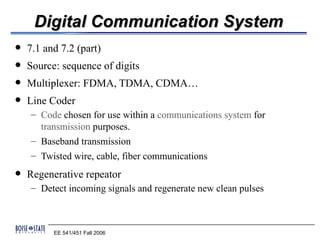
  7.1 and 7.2 (part)  Source: sequence of digits  Multiplexer: FDMA, TDMA, CDMA…  Line Coder – Code chosen for use within a communications system for transmission purposes. – Baseband transmission – Twisted wire, cable, fiber communications  Regenerative repeator – Detect incoming signals and regenerate new clean pulses EE 541/451 Fall 2006
  • 2. Line coding and decoding EE 541/451 Fall 2006
  • 3. Signal element versus data element EE 541/451 Fall 2006
  • 4. Data Rate Vs. Signal Rate  Data rate: the number of data elements (bits) sent in 1s (bps). It’s also called the bit rate  Signal rate: the number of signal elements sent in 1s (baud). It’s also called the pulse rate, the modulation rate, or the baud rate.  We wish to: – increase the data rate (increase the speed of transmission) – decrease the signal rate (decrease the bandwidth requirement) – worst case, best case, and average case of r – N bit rate – c is a constant that depends on different line codes. – S = c * N / r baud EE 541/451 Fall 2006
  • 5. Example • A signal is carrying data in which one data element is encoded as one signal element ( r = 1). If the bit rate is 100 kbps, what is the average value of the baud rate if c is between 0 and 1?  Solution – We assume that the average value of c is 1/2 . The baud rate is then • Although the actual bandwidth of a digital signal is infinite, the effective bandwidth is finite. • What is the relationship between baud rate, bit rate, and the required bandwidth? EE 541/451 Fall 2006
  • 6. Self-synchronization  Receiver Setting the clock matching the sender’s  Effect of lack of synchronization EE 541/451 Fall 2006
  • 7. Example • In a digital transmission, the receiver clock is 0.1 percent faster than the sender clock. How many extra bits per second does the receiver receive if the data rate is 1 kbps? How many if the data rate is 1 Mbps?  Solution – At 1 kbps, the receiver receives 1001 bps instead of 1000 bps. – At 1 Mbps, the receiver receives 1,001,000 bps instead of 1,000,000 bps. EE 541/451 Fall 2006
  • 8. Other properties  DC components  Transmission bandwidth  Power efficiency  Error detection and correction capability  Favorable power spectral density  Adequate timing content  Transparency EE 541/451 Fall 2006
  • 9. Line coding schemes EE 541/451 Fall 2006
  • 10. Unipolar NRZ scheme EE 541/451 Fall 2006
  • 11. Polar NRZ-L and NRZ-I schemes • In NRZ-L, the level of the voltage determines the value of the bit. RS232. • In NRZ-I, the inversion or the lack of inversion determines the value of the bit. USB, Compact CD, and Fast-Ethernet. • NRZ-L and NRZ-I both have an average signal rate of N/2 Bd.  NRZ-L and NRZ-I both have a DC component problem. EE 541/451 Fall 2006
  • 12. RZ scheme  Return to zero  Self clocking EE 541/451 Fall 2006
  • 13. Polar biphase: Manchester and differential Manchester schemes  In Manchester and differential Manchester encoding, the transition at the middle of the bit is used for synchronization.  The minimum bandwidth of Manchester and differential Manchester is 2 times that of NRZ. 802.3 token bus and 802.4 Ethernet EE 541/451 Fall 2006
  • 14. Bipolar schemes: AMI and pseudoternary  In bipolar encoding, we use three levels: positive, zero, and negative.  Pseudoternary: – 1 represented by absence of line signal – 0 represented by alternating positive and negative  DS1, E1 EE 541/451 Fall 2006
  • 15. Basic steps for spectrum analysis  Figure 7.3, 7.4 – Basic pulse function and its spectrum P(w) x For example, rect. function is sinc – Input x is the pulse function with different amplitude as figure 7.3c x Carry different information with sign and amplitude x Auto correlation is the spectrum of Sx(w) Tb Rn = lim T →∞ T ∑a a k k k +n 1 ∞ 1 ∞  ∑Re S x ( w) = Tb n =−∞ n − jnwTb =  R0 + 2∑ Rn e − jnwTb  Tb  n =1  – Overall spectrum 2 S y ( w) = P ( w) S y ( w) EE 541/451 Fall 2006
  • 16. Line coding schemes 10 points in the finals EE 541/451 Fall 2006
  • 17. NRZ  R0=1, Rn=0, n>0  Figure 7.5 pulse width Tb/2  P(w)=Tb sinc(wTb/2)  Bandwidth Rb for pulse width Tb EE 541/451 Fall 2006
  • 18. RZ scheme  DC Nulling ωT sin 2  Split phase r ( t ) ↔ R( ω ) = T 4 ωT  Figure 7.6(a) 4 EE 541/451 Fall 2006
  • 19. Polar biphase: Manchester and differential Manchester schemes  In Manchester and differential Manchester encoding, the transition at the middle of the bit is used for synchronization.  The minimum bandwidth of Manchester and differential Manchester is 2 times that of NRZ. 802.3 token bus and 802.4 Ethernet EE 541/451 Fall 2006
  • 20. Bipolar schemes: AMI and pseudoternary  R0=1/2, R1=-1/4, Rn=0,n>1, page 307 for reasons  Figure 7.8 2 P ( w) Tb  wT  2  wTb  S y ( w) = [ 1 − cos wTb ] = sin c 2  b  sin  2  2Tb 4  4     Reason: the phase changes slower EE 541/451 Fall 2006
  • 21. Multilevel: 2B1Q scheme  NRZ with amplitude representing more bits EE 541/451 Fall 2006
  • 22. HDB3 (High Density Bipolar of order 3 code)  Replacing series of four bits that are to equal to "0" with a code word "000V" or "B00V", where "V" is a pulse that violates the AMI law of alternate polarity and is rectangular or some other shape. The rules for using "000V" or "B00V" are as follows: – "B00V" is used when up to the previous pulse, the coded signal presents a DC component that is not null (the number of positive pulses is not compensated for by the number of negative pulses). – "000V" is used under the same conditions as above when up to the previous pulse the DC component is null. – The pulse "B" ("B" for balancing), which respects the AMI alternancy rule, has positive or negative polarity, ensuring that two successive V pulses will have different polarity.  Used in E1 EE 541/451 Fall 2006
  • 23. HDB3  The timing information is preserved by embedding it in the line signal even when long sequences of zeros are transmitted, which allows the clock to be recovered properly on reception.  The DC component of a signal that is coded in HDB3 is null. EE 541/451 Fall 2006
  • 24. Bipolar 8-Zero Substitution (B8ZS)  Adds synchronization for long strings of 0s  North American system  Same working principle as AMI except for eight consecutive 0s 10000000001  +000+-0-+01 in general 00000000000V(-V)0(-V)V 1 0 0 0 0 0 0 0 0 0 1 Amplitude Time Violation Violation  Evaluation – Adds synchronization without changing the DC balance – Error detection possible  Used in T1/DS1 EE 541/451 Fall 2006
  • 25. Coded Mark Inversion (CMI)  Another modification from AMI: Binary 0 is represented by a half period of negative voltage followed by a half period of positive voltage  Advantages: – good clock recovery and no d.c. offset – simple circuitry for encoder and decoder − compared with HDB3  Disadvantages: high bandwidth EE 541/451 Fall 2006
  • 26. Multilevel: 2B1Q scheme  Integrated Services Digital Network ISDN EE 541/451 Fall 2006
  • 27. mBnL schemes • In mBnL schemes, a pattern of m data elements is encoded as a pattern of n signal elements in which 2^m ≤ L^n. • Multilevel: 8B6T scheme, T4 EE 541/451 Fall 2006
  • 28. 8B6T code table (partial) EE 541/451 Fall 2006
  • 29. Multilevel: 4D-PAM5 scheme EE 541/451 Fall 2006
  • 30. Multitransition: MLT-3 scheme EE 541/451 Fall 2006
  • 31. PSD of various line codes EE 541/451 Fall 2006
  • 32. Clock Recovery  A timing reference signal can be extracted from the received signal by differentiation and full-wave rectification − provided that the signal carries sufficient transitions.  This timing reference signal is then used to fine tune the frequency and phase of a local oscillator. The receiver clock is then derived (e.g. add a phase shift) from this local oscillator. EE 541/451 Fall 2006
  • 33. Clock Recovery  Simple Circuit  PLL EE 541/451 Fall 2006
  • 34. Summary of line coding schemes Plus HDB3 and B8ZS EE 541/451 Fall 2006