SlideShare uma empresa Scribd logo
1 de 47
Baixar para ler offline
Design KIT:
Critical Conduction Mode (CRM)
PFC Circuit
All Rights Reserved Copyright (C) Bee Technologies Corporation 2010 1
Vac, in
C1
1uF
C2
200u
ILoad
0.5A
L1
12
Diode
D2
Q1
MOSFET
R7
L2
1 2
0
0
Rectifiers PFC
TB6819AFG
Controller
Circuit
PARAMETERS:
f req = 50Hz
Vin = 100Vac
Contents
• Introduction
• Application Circuit
• Design Specification
• Time Scaling
• Application Circuit with Time Scaling (tscale =10)
• Common Mode Choke Coil for PFC
• Design Steps (1-8)
• Switching Devices VPEAK and IPEAK at Steady State
• Switching Devices VPEAK and IPEAK at Start Up
Appendix
A.Excel Calculation Sheet
B.Simulation Index
All Rights Reserved Copyright (C) Bee Technologies Corporation 2012 2
Introduction
Most electronic ballasts and switching power supplies use a bridge rectifier
and a bulk storage capacitor to derive raw dc voltage from the utility ac line,
figure above: Vin=100Vac, 50Hz and PO=200W.
All Rights Reserved Copyright (C) Bee Technologies Corporation 2012 3
Vin
AC_IN1
PARAMETERS:
f req = 50Hz
Vin = 100Vac
AC_IN2
Cbulk
2000uF
0
bulkDB1
DB2DB3
Diode
DB4
Load
1.414Adc
Iline
Vbulk
Time
160ms 164ms 168ms 172ms 176ms 180ms 184ms 188ms 192ms 196ms 200ms
AVG(ABS(W(Vin)))/(RMS(ABS(V(AC_IN1,AC_IN2)))*RMS(ABS(I(Vin))))
0
0.2
0.4
0.6
0.8
1.0
ABS( I(Vin) )
0A
10A
20A
ABS( V(AC_IN1,AC_IN2) ) V(bulk)
0V
100V
200V
SEL>>
Introduction
The Uncorrected Power Factor rectifying circuit draws current from the ac line
when the ac voltage exceeds the capacitor voltage (Vbulk). The current (Iline) is non-
sinusoidal. This results in a poor power factor condition where the apparent input
power is much higher than the real power, figure above, power factor ratios of 0.5 to
0.7 are common.
All Rights Reserved Copyright (C) Bee Technologies Corporation 2012 4
|VAC, in, 100V| (VPEAK, in=100*2=141.42V) and Vbulk
|Iline|
Power Factor Ratio = Pin, avg./(Vin, rms* Iin, rms)
Vac, in
C1
1uF
C2
200u
ILoad
0.5A
L1
12
Diode
D2
Q1
MOSFET
R7
L2
1 2
0
0
Rectifiers PFC
TB6819AFG
Controller
Circuit
PARAMETERS:
f req = 50Hz
Vin = 100Vac
Introduction
The Power Factor Correction (PFC) circuit, as an off-line active preconverter, is
designed to draw a sinusoidal current from the AC line that is in phase with input
voltage. As a result, the power factor ratio is improved to be near to ideal (1).
The TB6819AFG is a critical conduction mode (CRM) PFC controller IC. The
description including equation and constants as a guide to understand its designing
process is included in this document.
All Rights Reserved Copyright (C) Bee Technologies Corporation 2012 5
Iline
VDC, OUT
Time*10
100ms 104ms 108ms 112ms 116ms 120ms 124ms 128ms 132ms 136ms 140ms
AVG(ABS(W(Vin))) / (RMS(ABS(V(AC_IN1,AC_IN2)))*RMS(ABS(I(Vin))))
0
0.2
0.4
0.6
0.8
1.0
-I(Vin)
-8.0A
0A
8.0A
SEL>>
1 V(AC_IN1,AC_IN2) 2 V(VOUT)
-160V
0V
160V
1
200V
400V
600V
2
>>
Introduction
The poor power factor load is corrected by keeping the ac line current sinusoidal and in
phase with the line voltage. This results with power factor ratio is 0.85.
All Rights Reserved Copyright (C) Bee Technologies Corporation 2012 6
VAC, in, 100V and VDC, OUT, 400V
Iline
Power Factor Ratio = 0.85
*simulation result at tscale = 10
Load
0.5A
R12
39k
C9
0.1uF
Vin
FREQ = {f req}
VAMPL = {Vin*1.414}
AC_IN1
R4 100
PARAMETERS:
f req = 50
Vin = 100
C6 3300p
AC_IN2
C1
1u
0
0
R9
3MEG
R10
22k
C5
10nF
C8
47uF
IC = 17.9
D5
DZ18V
R11
360k
R6
68k
R8
100k
MULT
Rtf
C3
0.47uF
IC = 3.74
L1
{L}
12
PARAMETERS:
L = 230u
N = {1/9.6}
N=N2/N1, L2=(N^2)*L1
VCC
V1
R7
0.11
POUT
V2
U1
TB6819AFG
FB_IN
COMP
MULT
ISZCD
GND
POUT
VCC
FB_IN
IS
ZCD
C7
8p
R3
10k
C4
1uF
VOUT
R2
1.5MEG
R1
9.53k
C2 200uF
IC = {2.51*1509.53/9.53}
COMP
L2
{N*N*L}
1 2
K
K1
COUPLING = 1
K_Linear
L1 = L1
L2 = L2
DB1
Diode
D2
Diode
D3
Diode
D4
DB2DB3
Diode
DB4
Q1
MOSFET
R5
10
Application Circuit
All Rights Reserved Copyright (C) Bee Technologies Corporation 2012 7
VAC, in=85-265VAC
PO = 200W,
VDC, OUT = 400VDC
*Analysis directives:
.TRAN 0 20ms 0 100n
.OPTIONS ABSTOL= 100n
.OPTIONS GMIN= 1.0E-8
.OPTIONS ITL1= 500
.OPTIONS ITL2= 200
.OPTIONS ITL4= 40
.OPTIONS RELTOL= 0.01
.OPTIONS VNTOL= 100u
Time
10ms 11ms 12ms 13ms 14ms 15ms 16ms 17ms 18ms 19ms 20ms
AVG(ABS(W(Vin)))/(RMS(ABS(V(AC_IN1,AC_IN2)))*RMS(ABS(I(Vin))))
0
0.5
1.0
Time
0s 2ms 4ms 6ms 8ms 10ms 12ms 14ms 16ms 18ms 20ms
-I(Vin)
-10A
0A
10A
SEL>>
1 V(AC_IN1,AC_IN2) 2 V(VOUT)
-200V
0V
200V
1
380V
400V
420V
2
>>
Application Circuit
All Rights Reserved Copyright (C) Bee Technologies Corporation 2012 8
VAC, in, 100V and VDC, OUT, 400V
Iline
Power Factor Ratio = 0.85
Total simulation time = 1429.49 seconds
Design Specification
This application circuit is for 400VDC/200W output
Critical Conduction Mode (CRM) PFC Circuit :
• VAC, in,min = 85 (VAC)
• VAC, in,max = 265 (VAC)
• VO = 400 (VDC)
• Po = 200 (W)
• fs = 20kHz ~ 150kHz, 50kHz
•  (assumed) = 90%
Control IC :
• Part # TTB6819AFG (PFC Controller IC)
• Switching Technique: Critical Conduction Mode (CRM)
All Rights Reserved Copyright (C) Bee Technologies Corporation 2012 9
Time Scaling
The transient (cycle-by-cycle) simulation of PFC circuits is really time (and memory)
consuming exercise, even with a fast computer.
There is a way to speed up simulations by artificially altering some of the key element values
by using of time scaling ratio (tscale), passed as a parameter to the simulation engine:
• Fline = F line  tscale
• C 2 = C 2  tscale
• C 3 = C 3  tscale
• C 4 = C 4  tscale
• C 5 = C 5  tscale
All Rights Reserved Copyright (C) Bee Technologies Corporation 2012 10
Application Circuit with Time Scaling (tscale =10)
All Rights Reserved Copyright (C) Bee Technologies Corporation 2012 11
VAC, in=85-265VAC
PO = 200W,
VDC, OUT = 400VDC
*Analysis directives:
.TRAN 0 2ms 0 100n
.OPTIONS ABSTOL= 100n
.OPTIONS GMIN= 1.0E-8
.OPTIONS ITL1= 500
.OPTIONS ITL2= 200
.OPTIONS ITL4= 40
.OPTIONS RELTOL= 0.01
.OPTIONS VNTOL= 100u
Load
0.5A
R12
39k
C9
0.1uF
Vin
FREQ = {f req*tscale}
VAMPL = {Vin*1.414}
AC_IN1
R4 100
PARAMETERS:
f req = 50
Vin = 100
C6 3300p
AC_IN2
C1
1u
0
0
R9
3MEG
R10
22k
C5
{10n/tscale}
C8
47uF
IC = 17.9
D5
DZ18V
R11
360k
R6
68k
R8
100k
MULT
Rtf
C3
{0.47u/tscale}
IC = 3.74
L1
{L}
12
PARAMETERS:
L = 230u
N = {1/9.6}
N=N2/N1, L2=(N^2)*L1
VCC
V1
R7
0.11
POUT
V2
U1
TB6819AFG
FB_IN
COMP
MULT
ISZCD
GND
POUT
VCC
FB_IN
IS
ZCD
C7
8p
R3
10k
C4
{1u/tscale}
VOUT
R2
1.5MEG
R1
9.53k
C2 {200u/tscale}
IC = {2.51*1509.53/9.53}
COMP
L2
{N*N*L}
1 2
K
K1
COUPLING = 1
K_Linear
L1 = L1
L2 = L2
DB1
Diode
D2
Diode
D3
Diode
D4
PARAMETERS:
tscale = 10
DB2DB3
Diode
DB4
Q1
MOSFET
R5
10
Time*10
10ms 11ms 12ms 13ms 14ms 15ms 16ms 17ms 18ms 19ms 20ms
AVG(ABS(W(Vin)))/(RMS(ABS(V(AC_IN1,AC_IN2)))*RMS(ABS(I(Vin))))
0
0.5
1.0
Time*10
0s 2ms 4ms 6ms 8ms 10ms 12ms 14ms 16ms 18ms 20ms
-I(Vin)
-10A
0A
10A
SEL>>
1 V(AC_IN1,AC_IN2) 2 V(VOUT)
-200V
0V
200V
1
380V
400V
420V
2
>>
Application Circuit with Time Scaling (tscale =10)
All Rights Reserved Copyright (C) Bee Technologies Corporation 2012 12
VAC, in, 100V and VDC, OUT, 400V
Iline
Power Factor Ratio = 0.85
Total simulation time = 132.41 seconds
Common Mode Choke Coil for PFC
To model a simple common mode choke coil, the
SPICE primitive k, which describes the coupling ratio
between L1 and L2, can be used.
COUPLING=1 of K_Linear means there is no leakage
inductance in the common mode choke coil model.
N is a ratio of L2 turns and L1 turns, or N2/N1
Input the parameters: L as an L1 inductance value
and N, then L2 is calculated using equation: L2 =
N2L1
All Rights Reserved Copyright (C) Bee Technologies Corporation 2012 13
L1
{L}
12
PARAMETERS:
L = 230u
N = {1/9.6}
N=N2/N1, L2=(N^2)*L1
L2
{N*N*L}
1 2
K
K1
COUPLING = 1
K_Linear
L1 = L1
L2 = L2
Design Steps (1-8)
(1) Output Voltage and Feedback Circuit
(2) Output Capacitor
(3) L1 Inductance
(4) Input Capacitor
(5) Auxiliary Winding L2
(6) Multiplier Input Circuit (MULT)
(7) Current Detection Circuit (IS)
(8) Zero Current Detection Circuit (ZCD)
All Rights Reserved Copyright (C) Bee Technologies Corporation 2012 14
(1) Output Voltage and Feedback Circuit
The output voltage is resistively divided and applied to the error amplifier, to set the VO
the R1 and R2 resistor value should satisfy the following equation :
*With VO=400V and R2=1.5M, R1 is calculated to be 9.47k, however a resistor of 9.53k , which
is available in the E96 series, is used as R1 (actual).
All Rights Reserved Copyright (C) Bee Technologies Corporation 2012 15
2.51
RR
RV
21
1O



Output DC Voltage, VO 400 V
Error Amplifier Reference Voltage Verr 2.51 V
R2 1.5 M
R1 9.47 k
R1 (actual) 9.53* k
(2) Output Capacitor
The output capacitance C2 is determined so that the PFC output ripple voltage dose not
exceed the VOPV-2, for the capacitor selection, the following equation should be satisfied:
The value of VOVP-2, min and Verr, min are inform in the TB6819AFG datasheet.
All Rights Reserved Copyright (C) Bee Technologies Corporation 2012 16
PO 200 W
fin 50 Hz
VO 400 V
VOVP-2, min 2.63 V
Verr, min 2.46 V
C2  41 F
C2used 200 F
  1-/VVV22
P
C2
err2-OVP
2
O
O


inf
Load
0.5A
R12
39k
C9
0.1uF
Vin
FREQ = {f req*tscale}
VAMPL = {Vin*1.414}
AC_IN1
R4 100
PARAMETERS:
f req = 50
Vin = 100
C6 3300p
AC_IN2
C1
1u
0
0
R9
3MEG
R10
22k
C5
{10n/tscale}
C8
47uF
IC = 17.9
D5
DZ18V
R11
360k
R6
68k
R8
100k
MULT
Rtf
C3
{0.47u/tscale}
IC = 3.74
L1
{L}
12
PARAMETERS:
L = 230u
N = {1/9.6}
N=N2/N1, L2=(N^2)*L1
VCC
V1
R7
0.11
POUT
V2
U1
TB6819AFG
FB_IN
COMP
MULT
ISZCD
GND
POUT
VCC
FB_IN
ISZCD
C7
8p
R3
10k
C4
{1u/tscale}
VOUT
R2
1.5MEG
R1
9.53k
C2 {200u/tscale}
IC = {2.51*1509.53/9.53}
PARAMETERS:
tscale = 10
COMP
L2
{N*N*L}
1 2
K
K1
COUPLING = 1
K_Linear
L1 = L1
L2 = L2
DB1
Diode
D2
Diode
D3
Diode
D4
DB2DB3
Diode
DB4
Q1
MOSFET
R5
10
Simulation of Step (1) and (2)
All Rights Reserved Copyright (C) Bee Technologies Corporation 2012 17
Vin = 100Vac with
frequency 50Hz,
tscale = 10
R1=9.53k and
R2=1.5M
Iload = 0.5A as
PO=200W at
VO=400V
C2 =
200F
*Analysis directives:
.TRAN 0 4ms 0 100n
.OPTIONS ABSTOL= 100n
.OPTIONS GMIN= 1.0E-8
.OPTIONS ITL1= 500
.OPTIONS ITL2= 200
.OPTIONS ITL4= 40
.OPTIONS RELTOL= 0.01
.OPTIONS VNTOL= 100u
Time*10
0s 5ms 10ms 15ms 20ms 25ms 30ms 35ms 40ms
V(FB_IN) 2.63 2.46
2.4
2.6
2.8
V(VOUT)
380V
400V
420V
SEL>>
V(AC_IN1,AC_IN2)
-200V
0V
200V
Simulation of Step (1) and (2)
All Rights Reserved Copyright (C) Bee Technologies Corporation 2012 18
VAC, in,=100V (VPEAK, in,=100*1.4142=141.4V)
V(FB IN), VOVP-2, min.(2.63V), and Verr,min(2.46V)
VO=400Vdc with 2fline ripple
Total simulation time = 270.61 seconds
(3) L1 Inductance
The switching frequencyfs (Hz) depends on the L1 inductance and
input/output condition which the equation and the calculation data are as shown
below.
*The fs value should be within 20kHz and 150kHz, to avoid an occurrence of EMI
problem, fs=50kHz is used.
All Rights Reserved Copyright (C) Bee Technologies Corporation 2012 19
OO
2
minin,AC,minin,AC,O
PVfs1002
V)V2(V
L1



η
Output DC Voltage, VO 400 V
Minimum AC Input Voltage, VAC, in, min 85 V
Power Efficiency,  (assumed) 90 %
Switching Frequency, fs* 50 kHz
Output Power, PO 200 W
Calculated Inductance, L1(calculated) 227 H
Selected (Actual) Inductance, L1(actual) 230 H
(4) Input Capacitor
C1 should be capable of supplying energy stored in the L1 while the FET is on. Assumed
that the on/off duty is 50%, the C1 should be temporarily able to supply twice the current.
A current reaches its maximum at the VAC, in, min. Thus, the following relationship should
be satisfied:
All Rights Reserved Copyright (C) Bee Technologies Corporation 2012 20
L1 230 H
PO 200 W
VAC, in, min 85 V
C1  0.35 F
C1used 1 F
4
minin,AC,
2
O
V
PL12
C1


Load
0.5A
R12
39k
C9
0.1uF
Vin
FREQ = {f req*tscale}
VAMPL = {Vin*1.414}
AC_IN1
R4 100
PARAMETERS:
f req = 50
Vin = 85
C6 3300p
AC_IN2
C1
1u
0
0
R9
3MEG
R10
22k
C5
{10n/tscale}
C8
47uF
IC = 17.9
D5
DZ18V
R11
360k
R6
68k
R8
100k
MULT
Rtf
C3
{0.47u/tscale}
IC = 4.22
L1
{L}
12
PARAMETERS:
L = 230u
N = {1/9.6}
N=N2/N1, L2=(N^2)*L1
VCC
V1
R7
0.11
POUT
V2
U1
TB6819AFG
FB_IN
COMP
MULT
ISZCD
GND
POUT
VCC
FB_IN
ISZCD
C7
8p
R3
10k
C4
{1u/tscale}
VOUT
R2
1.5MEG
R1
9.53k
C2 {200u/tscale}
IC = {2.51*1509.53/9.53}
PARAMETERS:
tscale = 10
COMP
L2
{N*N*L}
1 2
K
K1
COUPLING = 1
K_Linear
L1 = L1
L2 = L2
DB1
Diode
D2
Diode
D3
Diode
D4
DB2DB3
Diode
DB4
Q1
MOSFET
R5
10
Simulation of Step (3) and (4)
All Rights Reserved Copyright (C) Bee Technologies Corporation 2012 21
Vin, min = 85Vac with
frequency 50Hz,
tscale = 10
Iload = 0.5A as
PO=200W at
VO=400V
The Calculated L1 value
227H (adjusted 230H
is used)
I(L1)
C1 = 1F
*Analysis directives:
.TRAN 0 20ms 16m 100n
.OPTIONS ABSTOL= 100n
.OPTIONS GMIN= 1.0E-8
.OPTIONS ITL1= 500
.OPTIONS ITL2= 200
.OPTIONS ITL4= 40
.OPTIONS RELTOL= 0.01
.OPTIONS VNTOL= 100u
Time
16.45ms 16.46ms 16.47ms 16.48ms 16.49ms 16.50ms 16.51ms 16.52ms 16.53ms 16.54ms 16.55ms
V(POUT)
0V
10V
20V
-I(L1)
0A
5A
10A
V(VOUT)
395V
400V
405V
SEL>>
Simulation of Step (3) and (4)
All Rights Reserved Copyright (C) Bee Technologies Corporation 2012 22
VO=400Vdc with high switching ripple
I(L1)
Switching Control Signal, fs = 48.4 kHz
Total simulation time = 976.83 seconds
(5) Auxiliary Winding L2
The auxiliary winding L2 is used to detect the zero inductor current condition of the inductor L1.
Since the maximum reference voltage for the ZCD comparator is 1.9V (the IC specification) ,
N1/N2 should meet the following condition:
Where N1 is the number of winding of turns of L1, N2 is that of L2
*To ensure that the design requirements are met, N1/N2 should preferably about 10 (9.6 is
used) to allow for design margins.
All Rights Reserved Copyright (C) Bee Technologies Corporation 2012 23
9.1
maxin,AC,O V2V
N1/N2


Output DC Voltage, VO 400 V
Maximum AC Input Voltage, VAC, in, max 265 V
Calculated Turn Number Ratio, N1/N2 < 14
Selected Transformer Turn Ratio, N1/N2 (actual) 9.6*
Load
0.5A
R12
39k
C9
0.1uF
Vin
FREQ = {f req*tscale}
VAMPL = {Vin*1.414}
AC_IN1
R4 100
PARAMETERS:
f req = 50
Vin = 265
C6 3300p
AC_IN2
C1
1u
0
0
R9
3MEG
R10
22k
C5
{10n/tscale}
C8
47uF
IC = 17.9
D5
DZ18V
R11
360k
R6
68k
R8
100k
MULT
Rtf
C3
{0.47u/tscale}
IC = 2.533
L1
{L}
12
PARAMETERS:
L = 230u
N = {1/9.6}
N=N2/N1, L2=(N^2)*L1
VCC
V1
R7
0.11
POUT
V2
U1
TB6819AFG
FB_IN
COMP
MULT
ISZCD
GND
POUT
VCC
FB_IN
ISZCD
C7
8p
R3
10k
C4
{1u/tscale}
VOUT
R2
1.5MEG
R1
9.53k
C2 {200u/tscale}
IC = {2.51*1509.53/9.53}
PARAMETERS:
tscale = 10
COMP
L2
{N*N*L}
1 2
K
K1
COUPLING = 1
K_Linear
L1 = L1
L2 = L2
DB1
Diode
D2
Diode
D3
Diode
D4
DB2DB3
Diode
DB4
Q1
MOSFET
R5
10
Simulation of Step (5)
All Rights Reserved Copyright (C) Bee Technologies Corporation 2012 24
N1/N2=9.6, input
parameter N =
N2/N1 = 1/9.6
I(L1)
Vin, min = 265Vac with
frequency 50Hz,
tscale = 10
Iload = 0.5A as
PO=200W at
VO=400V
*Analysis directives:
.TRAN 0 4ms 2ms 100n
.OPTIONS ABSTOL= 100n
.OPTIONS GMIN= 1.0E-8
.OPTIONS ITL1= 500
.OPTIONS ITL2= 200
.OPTIONS ITL4= 40
.OPTIONS RELTOL= 0.01
.OPTIONS VNTOL= 100u
Time*10
20ms 22ms 24ms 26ms 28ms 30ms 32ms 34ms 36ms 38ms 40ms
V(ZCD) 1.9
0
2.5
5.0
7.5
-I(L1)
0A
2.5A
5.0A
V(VOUT)
375V
400V
425V
SEL>>
V(AC_IN1,AC_IN2)
-400V
0V
400V
Simulation of Step (5)
All Rights Reserved Copyright (C) Bee Technologies Corporation 2012 25
VO=400V and PO=200W
VAC, in, min=265V (VPEAK, in, min=265*1.4142=374.8V)
I(L1)
V(ZCD) and the maximum reference voltage of the TB6819AFG’s ZCD comparator, 1.9V
Total simulation time = 1012.86 seconds
(6) Multiplier Input Circuit (MULT)
The AC input supply voltage (sinewave) is applied to the multiplier by dividing a full-wave
rectified voltage waveform.
The IC startup threshold voltages of the Brown Out Protection (BOP) function = 0.75V and
the MULT linear input voltage range of the multiplier = 0 to 3V, the R9 and R10 resistor should
satisfy the following condition:
with excel calculation sheet PFC_Cal-Sht.xlsx you can input R9 and R10 values, then check the
calculated BOP and Linear MULT values to be within the maximum values.
All Rights Reserved Copyright (C) Bee Technologies Corporation 2012 26
109
10minin,AC,
RR
R2V
0


75.
Maximum AC Input Voltage, VAC, in, min 400 V
Maximum AC Input Voltage, VAC, in, max 265 V
R9 3 M
R10 22 k
Minimum Condition for BOP 0.875 > 0.75
Maximum Condition for Linear MULT 2.728 < 3
3


109
10maxin,AC,
RR
R2V
and
Load
0.5A
R12
39k
C9
0.1uF
Vin
FREQ = {f req*tscale}
VAMPL = {Vin*1.414}
AC_IN1
R4 100
PARAMETERS:
f req = 50
Vin = 265
C6 3300p
AC_IN2
C1
1u
0
0
R9
3MEG
R10
22k
C5
{10n/tscale}
C8
47uF
IC = 17.9
D5
DZ18V
R11
360k
R6
68k
R8
100k
MULT
Rtf
C3
{0.47u/tscale}
IC = 2.533
L1
{L}
12
PARAMETERS:
L = 230u
N = {1/9.6}
N=N2/N1, L2=(N^2)*L1
VCC
V1
R7
0.11
POUT
V2
U1
TB6819AFG
FB_IN
COMP
MULT
ISZCD
GND
POUT
VCC
FB_IN
ISZCD
C7
8p
R3
10k
C4
{1u/tscale}
VOUT
R2
1.5MEG
R1
9.53k
C2 {200u/tscale}
IC = {2.51*1509.53/9.53}
PARAMETERS:
tscale = 10
COMP
L2
{N*N*L}
1 2
K
K1
COUPLING = 1
K_Linear
L1 = L1
L2 = L2
DB1
Diode
D2
Diode
D3
Diode
D4
DB2DB3
Diode
DB4
Q1
MOSFET
R5
10
Simulation of Step (6) at Vin, max
All Rights Reserved Copyright (C) Bee Technologies Corporation 2012 27
Vin, max = 265Vac with
frequency 50Hz,
tscale = 10
Iload = 0.5A as
PO=200W at
VO=400V
R10=3M and
R11=22k*Analysis directives:
.TRAN 0 4ms 2ms 100n
.OPTIONS ABSTOL= 100n
.OPTIONS GMIN= 1.0E-8
.OPTIONS ITL1= 500
.OPTIONS ITL2= 200
.OPTIONS ITL4= 40
.OPTIONS RELTOL= 0.01
.OPTIONS VNTOL= 100u
Time*10
20ms 22ms 24ms 26ms 28ms 30ms 32ms 34ms 36ms 38ms 40ms
V(MULT) 3
0
1.0
2.0
3.0
4.0
V(Rtf)
0V
100V
200V
300V
400V
V(AC_IN1,AC_IN2)
-400V
-200V
0V
200V
400V
SEL>>
Simulation of Step (6) at Vin, max
All Rights Reserved Copyright (C) Bee Technologies Corporation 2012 28
Full-wave rectified voltage
VAC, in, max=265V (VPEAK, in, min=265*1.4142=374.8V)
V(MULT) < MULT linear input maximum voltage (3V)
Total simulation time = 1012.86 seconds
Load
0.5A
R12
39k
C9
0.1uF
Vin
FREQ = {f req*tscale}
VAMPL = {Vin*1.414}
AC_IN1
R4 100
PARAMETERS:
f req = 50
Vin = 85
C6 3300p
AC_IN2
C1
1u
0
0
R9
3MEG
R10
22k
C5
{10n/tscale}
C8
47uF
IC = 17.9
D5
DZ18V
R11
360k
R6
68k
R8
100k
MULT
Rtf
C3
{0.47u/tscale}
IC = 4.22
L1
{L}
12
PARAMETERS:
L = 230u
N = {1/9.6}
N=N2/N1, L2=(N^2)*L1
VCC
V1
R7
0.11
POUT
V2
U1
TB6819AFG
FB_IN
COMP
MULT
ISZCD
GND
POUT
VCC
FB_IN
ISZCD
C7
8p
R3
10k
C4
{1u/tscale}
VOUT
R2
1.5MEG
R1
9.53k
C2 {200u/tscale}
IC = {2.51*1509.53/9.53}
PARAMETERS:
tscale = 10
COMP
L2
{N*N*L}
1 2
K
K1
COUPLING = 1
K_Linear
L1 = L1
L2 = L2
DB1
Diode
D2
Diode
D3
Diode
D4
DB2DB3
Diode
DB4
Q1
MOSFET
R5
10
Simulation of Step (6) at Vin, min
All Rights Reserved Copyright (C) Bee Technologies Corporation 2012 29
R10=3M and
R11=22k
Vin, min = 85Vac with
frequency 50Hz,
tscale = 10
Iload = 0.5A as
PO=200W at
VO=400V
*Analysis directives:
.TRAN 0 20ms 16m 100n
.OPTIONS ABSTOL= 100n
.OPTIONS GMIN= 1.0E-8
.OPTIONS ITL1= 500
.OPTIONS ITL2= 200
.OPTIONS ITL4= 40
.OPTIONS RELTOL= 0.01
.OPTIONS VNTOL= 100u
Time*10
180ms 182ms 184ms 186ms 188ms 190ms 192ms 194ms 196ms 198ms 200ms
V(MULT) 0.75
0
0.5
1.0
V(Rtf)
0V
40V
80V
120V
SEL>>
V(AC_IN1,AC_IN2)
-200V
0V
200V
Simulation of Step (6) at Vin, min
All Rights Reserved Copyright (C) Bee Technologies Corporation 2012 30
Full-wave rectified voltage
VAC, in, min=85V (VPEAK, in, min=85*1.4142=120.2V)
V(MULT) > BOP threshold voltage (0.75V)
Total simulation time = 976.83 seconds
(7) Current Detection Circuit (IS)
Iq1 (power switch current) is converted into voltage by R7, then applied to the IS pin. The R7
resistor value calculation follows these steps:
1) The maximum current of the Q1 current, Iq1 (max) should allow the output power PO to meet
the specification. Therefore, the following equation should be satisfied:
2) the IS pin peak voltage (Visp) is calculated using the following equation:
3) R7 = Visp / Iq1(max.).
All Rights Reserved Copyright (C) Bee Technologies Corporation 2012 31
R10R9
R102V0.65
Visp minin,AC,



Minimum ac input voltage, VAC, in, min 85 V
Output power, PO 200 W
Power efficiency,  (assumed) 90 %
R9 3 M
R10 22 k
Power switch current, Iq1(max.) 5.23 A
TB6819AFG IS pin peak voltage Visp 0.57 V
R7 0.11 
)2V(η
22100P
Iq1(max.)
minin,AC,
O



Load
0.5A
R12
39k
C9
0.1uF
Vin
FREQ = {f req*tscale}
VAMPL = {Vin*1.414}
AC_IN1
R4 100
PARAMETERS:
f req = 50
Vin = 85
C6 3300p
AC_IN2
C1
1u
0
0
R9
3MEG
R10
22k
C5
{10n/tscale}
C8
47uF
IC = 17.9
D5
DZ18V
R11
360k
R6
68k
R8
100k
MULT
Rtf
C3
{0.47u/tscale}
IC = 4.22
L1
{L}
12
PARAMETERS:
L = 230u
N = {1/9.6}
N=N2/N1, L2=(N^2)*L1
VCC
V1
R7
0.11
POUT
V2
U1
TB6819AFG
FB_IN
COMP
MULT
ISZCD
GND
POUT
VCC
FB_IN
ISZCD
C7
8p
R3
10k
C4
{1u/tscale}
VOUT
R2
1.5MEG
R1
9.53k
C2 {200u/tscale}
IC = {2.51*1509.53/9.53}
PARAMETERS:
tscale = 10
COMP
L2
{N*N*L}
1 2
K
K1
COUPLING = 1
K_Linear
L1 = L1
L2 = L2
DB1
Diode
D2
Diode
D3
Diode
D4
DB2DB3
Diode
DB4
Q1
MOSFET
R5
10
Simulation of Step (7)
All Rights Reserved Copyright (C) Bee Technologies Corporation 2012 32
Iq1
R7 =
0.11
Vin, min = 85Vac with
frequency 50Hz,
tscale = 10
Iload = 0.5A as
PO=200W at
VO=400V
R10=3M and
R11=22k*Analysis directives:
.TRAN 0 20ms 16m 100n
.OPTIONS ABSTOL= 100n
.OPTIONS GMIN= 1.0E-8
.OPTIONS ITL1= 500
.OPTIONS ITL2= 200
.OPTIONS ITL4= 40
.OPTIONS RELTOL= 0.01
.OPTIONS VNTOL= 100u
Simulation of Step (7)
All Rights Reserved Copyright (C) Bee Technologies Corporation 2012 33
Time*10
180ms 182ms 184ms 186ms 188ms 190ms 192ms 194ms 196ms 198ms 200ms
V(IS)
0V
0.5V
1.0V
ID(Q1)
0A
2.0A
4.0A
6.0A
8.0A
SEL>>
V(MULT)
0V
0.5V
1.0V
Iq1
V(MULT)
V(IS)
Total simulation time = 976.83 seconds
(8) Zero Current Detection Circuit (ZCD)
The auxiliary winding L2 is connected to the ZCD pin. The current through L2 is limited to ZCD
pin rated current (3mA) by using the current limiting resistor R6. The following relationship
should be satisfied depending on whether the external FET is on or off:
FET = On:
FET = Off:
A resistor of 68k is used for limiting the current to 1/5 of the rated current
All Rights Reserved Copyright (C) Bee Technologies Corporation 2012 34
VAC, in, max 265 V
N2/N1 1/9.6 W
VO 400 V
FET = ON, R6 > 13.0 k
FET = OFF, R6 > 13.9 k
R6 (actual) 68 k
 
3mA
N2/N12V
R6 max.in,AC, 

 
3mA
N2/N1V
R6 O 

Load
0.5A
R12
39k
C9
0.1uF
Vin
FREQ = {f req*tscale}
VAMPL = {Vin*1.414}
AC_IN1
R4 100
PARAMETERS:
f req = 50
Vin = 265
C6 3300p
AC_IN2
C1
1u
0
0
R9
3MEG
R10
22k
C5
{10n/tscale}
C8
47uF
IC = 17.9
D5
DZ18V
R11
360k
R6
68k
R8
100k
MULT
Rtf
C3
{0.47u/tscale}
IC = 2.533
L1
{L}
12
PARAMETERS:
L = 230u
N = {1/9.6}
N=N2/N1, L2=(N^2)*L1
VCC
V1
R7
0.11
POUT
V2
U1
TB6819AFG
FB_IN
COMP
MULT
ISZCD
GND
POUT
VCC
FB_IN
ISZCD
C7
8p
R3
10k
C4
{1u/tscale}
VOUT
R2
1.5MEG
R1
9.53k
C2 {200u/tscale}
IC = {2.51*1509.53/9.53}
PARAMETERS:
tscale = 10
COMP
L2
{N*N*L}
1 2
K
K1
COUPLING = 1
K_Linear
L1 = L1
L2 = L2
DB1
Diode
D2
Diode
D3
Diode
D4
DB2DB3
Diode
DB4
Q1
MOSFET
R5
10
Simulation of Step (8)
All Rights Reserved Copyright (C) Bee Technologies Corporation 2012 35
ON/OFF
R6 =
68k
Vin, max = 265Vac with
frequency 50Hz,
tscale = 10
Iload = 0.5A as
PO=200W at
VO=400V
R10=3M and
R11=22k*Analysis directives:
.TRAN 0 4ms 2ms 100n
.OPTIONS ABSTOL= 100n
.OPTIONS GMIN= 1.0E-8
.OPTIONS ITL1= 500
.OPTIONS ITL2= 200
.OPTIONS ITL4= 40
.OPTIONS RELTOL= 0.01
.OPTIONS VNTOL= 100u
Time*10
20ms 22ms 24ms 26ms 28ms 30ms 32ms 34ms 36ms 38ms 40ms
I(R6) 3m/5
-1.0m
0
1.0m
V(VOUT)
375V
400V
425V
V(AC_IN1,AC_IN2)
-400V
0V
400V
SEL>>
Simulation of Step (8)
All Rights Reserved Copyright (C) Bee Technologies Corporation 2012 36
VAC, in, max=265V
V(VOUT)
I(R6) and 1/5 of the ZCD rated current (3mA/5)
Total simulation time = 1012.86 seconds
Load
0.5A
R12
39k
C9
0.1uF
Vin
FREQ = {f req*tscale}
VAMPL = {Vin*1.414}
AC_IN1
R4 100
PARAMETERS:
f req = 50
Vin = 85
C6 3300p
AC_IN2
C1
1u
0
0
R9
3MEG
R10
22k
C5
{10n/tscale}
C8
47uF
IC = 17.9
D5
DZ18V
R11
360k
R6
68k
R8
100k
MULT
Rtf
C3
{0.47u/tscale}
IC = 4.22
L1
{L}
12
PARAMETERS:
L = 230u
N = {1/9.6}
N=N2/N1, L2=(N^2)*L1
VCC
V1
R7
0.11
POUT
V2
U1
TB6819AFG
FB_IN
COMP
MULT
ISZCD
GND
POUT
VCC
FB_IN
ISZCD
C7
8p
R3
10k
C4
{1u/tscale}
VOUT
R2
1.5MEG
R1
9.53k
C2 {200u/tscale}
IC = {2.51*1509.53/9.53}
PARAMETERS:
tscale = 10
COMP
L2
{N*N*L}
1 2
K
K1
COUPLING = 1
K_Linear
L1 = L1
L2 = L2
DB1
Diode
D2
Diode
D3
Diode
D4
DB2DB3
Diode
DB4
Q1
MOSFET
R5
10
Switching Devices VPEAK and IPEAK at Steady State
All Rights Reserved Copyright (C) Bee Technologies Corporation 2012 37
Vin, min = 85Vac with
frequency 50Hz,
tscale = 10
Iload = 0.5A as
PO=200W at
VO=400V
I(D2)
Switching
Diode, D2
*Analysis directives:
.TRAN 0 20ms 16m 100n
.OPTIONS ABSTOL= 100n
.OPTIONS GMIN= 1.0E-8
.OPTIONS ITL1= 500
.OPTIONS ITL2= 200
.OPTIONS ITL4= 40
.OPTIONS RELTOL= 0.01
.OPTIONS VNTOL= 100u
ID(Q1)
Switching
MOSFET, Q1
Time
18.00ms 18.25ms 18.50ms 18.75ms 19.00ms 19.25ms 19.50ms 19.75ms 20.00ms
ID(Q1)
-6A
0A
6A
12A
V(Q1:d,Q1:s)
0V
200V
400V
600V
I(D2)
8A
16A
-2A
SEL>>
V(D2:2,D2:1)
0V
200V
400V
600V
Switching Devices VPEAK and IPEAK at Steady State
All Rights Reserved Copyright (C) Bee Technologies Corporation 2012 38
D2 VKA, Peak ≈ 400V at steady state
Total simulation time = 976.83 seconds
D2 IF, Peak ≈ 12A at steady state
Q1 VDS, Peak ≈ 400V at steady state
Q1 ID, Peak ≈ 7.2A at steady state
Load
0.5A
R12
39k
C9
0.1uF
Vin
FREQ = {f req*tscale}
VAMPL = {Vin*1.414}
AC_IN1
R4 100
PARAMETERS:
f req = 50
Vin = 85
C6 3300p
AC_IN2
C1
1u
0
0
R9
3MEG
R10
22k
C5
{10n/tscale}
C8
47uF
IC = 17.9
D5
DZ18V
R11
360k
R6
68k
R8
100k
MULT
Rtf
C3
{0.47u/tscale}
L1
{L}
12
PARAMETERS:
L = 230u
N = {1/9.6}
N=N2/N1, L2=(N^2)*L1
VCC
V1
R7
0.11
POUT
V2
U1
TB6819AFG
FB_IN
COMP
MULT
ISZCD
GND
POUT
VCC FB_IN
ISZCD
C7
8p
R3
10k
C4
{1u/tscale}
VOUT
R2
1.5MEG
R1
9.53k
C2 {200u/tscale}
PARAMETERS:
tscale = 40
COMP
L2
{N*N*L}
1 2
K
K1
COUPLING = 1
K_Linear
L1 = L1
L2 = L2
DB1
Diode
D2
Diode
D3
Diode
D4
DB2DB3
Diode
DB4
Q1
MOSFET
R5
10
Switching Devices VPEAK and IPEAK at Start Up
All Rights Reserved Copyright (C) Bee Technologies Corporation 2012 39
Vin, min = 85Vac with
frequency 50Hz,
tscale = 40
Iload = 0.5A as
PO=200W at
VO=400V
I(D2)
Switching
Diode, D2
*Analysis directives:
.TRAN 0 10ms 0m 100n
.OPTIONS ABSTOL= 100n
.OPTIONS GMIN= 1.0E-8
.OPTIONS ITL1= 500
.OPTIONS ITL2= 200
.OPTIONS ITL4= 40
.OPTIONS RELTOL= 0.01
.OPTIONS VNTOL= 100u
ID(Q1)
Switching
MOSFET, Q1
Rectifier
Diode, DB1-4
Time*40
0s 40ms 80ms 120ms 160ms 200ms 240ms 280ms 320ms 360ms 400ms
1 V(Q1:d,Q1:s) 2 ID(Q1)
-500V
0V
500V
1
-10A
0A
10A
2
>>
1 V(D2:2,D2:1) 2 I(D2)
0V
200V
400V
600V
1
SEL>>
0A
6A
12A
18A
2
SEL>>
1 V(DB1:2,DB1:1) 2 I(DB1)
100V
200V
-10V
1
>>
0A
8A
16A
2
V(VOUT)
0V
200V
400V
600V
Switching Devices VPEAK and IPEAK at Start Up
All Rights Reserved Copyright (C) Bee Technologies Corporation 2012 40
V(VOUT) at start up
Total simulation time = 733.5 seconds
D2 VKA, Peak ≈ 400V and IF, Peak ≈ 16A at start up
Q1 VDS, Peak ≈ 400V and ID, Peak ≈ 10A at start up
DB1-4 IF, Peak ≈ 10A at start up
Load
0.5A
R12
39k
Q2
2SK2611
C9
0.1uF
Vin
FREQ = {f req*tscale}
VAMPL = {Vin*1.414}
AC_IN1
R4 100
PARAMETERS:
f req = 50
Vin = 100
C6 3300p
AC_IN2
C1
1u
0
0
R9
3MEG
R10
22k
C5
{10n/tscale}
C8
47uF
IC = 17.9
D5
DZ18V
R11
360k
R6
68k
R8
100k
MULT
Rtf
C3
{0.47u/tscale}
IC = 3.74
L1
{L}
12
PARAMETERS:
L = 230u
N = {1/9.6}
N=N2/N1, L2=(N^2)*L1
VCC
V1
R7
0.11
POUT
V2
U1
TB6819AFG
FB_IN
COMP
MULT
ISZCD
GND
POUT
VCC
FB_IN
ISZCD
C7
8p
R3
10k
C4
{1u/tscale}
VOUT
R2
1.5MEG
R1
9.53k
COMP
L2
{N*N*L}
1 2
K
K1
COUPLING = 1
K_Linear
L1 = L1
L2 = L2
C2
RJJ-35V221MG5-T20
D2
SCS110AG
DB1
Diode
D3
Diode
D4
PARAMETERS:
tscale = 10
DB2DB3
Diode
DB4
R5
10
Simulation with Models from the SpicePark (1/4)
All Rights Reserved Copyright (C) Bee Technologies Corporation 2012 41
Capacitor
model
MOSFET
professional
model
Schottky diode
model
Replace some default model with models from SpicePark
*Analysis directives:
.TRAN 0 2ms 0 100n
.OPTIONS ABSTOL= 100n
.OPTIONS GMIN= 1.0E-8
.OPTIONS ITL1= 500
.OPTIONS ITL2= 200
.OPTIONS ITL4= 100
.OPTIONS RELTOL= 0.01
.OPTIONS VNTOL= 100u
Time
484us 488us 492us 496us 500us 504us 508us 512us 516us 520us 524us
V(V2)
0V
40V
-I(L1)
0A
5A
10A
V(V1)
0V
250V
500V
V(Q2:g)
10V
20V
SEL>>
Time
0s 0.2ms 0.4ms 0.6ms 0.8ms 1.0ms 1.2ms 1.4ms 1.6ms 1.8ms 2.0ms
V(VOUT)
392V
400V
Simulation with Models from the SpicePark (2/4)
All Rights Reserved Copyright (C) Bee Technologies Corporation 2012 42
V(VOUT) with high frequency ripple which is caused by ESR and ESL of the capacitor model.
Gate charge characteristics is include in the MOSFET Professional model.
V(V1)
I (L1)
V(V2)
Total simulation time = 408.13 seconds
Time
476us 480us 484us 488us 492us 496us 500us 504us 508us 512us 516us
V(V2)
0V
40V
-I(L1)
0A
5A
10A
V(V1)
0V
250V
500V
V(Q1:g)
10V
20V
SEL>>
Time
0s 0.5ms 1.0ms 1.5ms 2.0ms
V(VOUT)
392V
400V
Simulation with Models from the SpicePark (3/4)
All Rights Reserved Copyright (C) Bee Technologies Corporation 2012 43
The Simulation Waveform with the defaults models
V(V1)
I (L1)
V(V2)
V(VOUT) without high frequency ripple which is caused by ESR and ESL of the capacitor model.
Gate charge characteristics is not include in the default model.
Total simulation time = 132.41 seconds
Simulation with Models from the SpicePark (1/4)
All Rights Reserved Copyright (C) Bee Technologies Corporation 2012 44
SpicePark of MOSFET model
Select the device which is
capable of handling the
simulated peak values.
Excel Calculation Sheet (1/2)
All Rights Reserved Copyright (C) Bee Technologies Corporation 2012 45
Design Specification
VAC, in,min 85 V
VAC, in,max 265 V
fin 50 Hz
VO 400 V
PO 200 W
fs 50 kHz
 (assumed) 90 %
(1) Output Voltage & Feedback Circuit
R2 1.5 M ; Input R2 value, the R1 for the VO specification is
auto-calculatedR1 9.47 k
R1 (actual) 9.53 k
(2) Output Capacitor
VOVP-2, MIN. 2.63 V ; VOVP-2, MIN. and Verr, MIN. are TB6819AFG electrical
characteristicsVerr, MIN. 2.46 V
C2 ³ 41 uF
(3) L1 Inductance
L1 227 mH
L1(actual) 230 mH
Excel Calculation Sheet (2/2)
All Rights Reserved Copyright (C) Bee Technologies Corporation 2012 46
(4) Input Capacitor
C1 ³ 0.35 F
C1(actual) 1 F
(5) Auxiliary Winding L2
N1/N2 < 14
N1/N2(actual) 9.6
(6) Multiplier Input Circuit (MULT)
R9 3 M ; Input R9 and R10 values, then check the BOP and
the Linear MULT valuesR10 22 k
Codition:
BOP 0.875 > 0.75
Linear MULT 2.728 < 3
(7) Current Detection Circuit (IS)
Iq1(max.) 5.23 A
Visp 0.57 V
R7 0.11 
(8) Zero Current Detection Circuit (ZCD)
FET=ON, R8 > 13.0 k
FET=OFF, R8 > 13.9 k
R8 (actual) 68 k ; limiting the current to 1/5 of the rated current.
Remark
Input your design specification and your selected parameters. The numbers in the green font are auto-
calculated numbers. The numbers in the blue font are the design actual selected (used) number.
Simulation Index
All Rights Reserved Copyright (C) Bee Technologies Corporation 2012 47
Simulations Folder name
1. Application Circuit.......................................................................
2. Application Circuit with Time Scaling (tscale =10).........................
3. Simulation of Step (1) and (2).....................................................
4. Simulation of Step (3) and (4).....................................................
5. Simulation of Step (5).................................................................
6. Simulation of Step (6) at Vin, max..................................................
7. Simulation of Step (6) at Vin, min...................................................
8. Simulation of Step (7).................................................................
9. Simulation of Step (8).................................................................
10. Switching Devices VPEAK and IPEAK at Steady State...................
11. Switching Devices VPEAK and IPEAK at Start Up...........................
APPCKT
APPCKT_tscale
STEP1-2
STEP3-4
STEP5
STEP6_INMAX
STEP6_INMIN
STEP7
STEP8
IVPEAK-SS
IVPEAK-SU
Libraries :
1. ..¥part¥tb6819afg¥tb6819afg.lib
2. ..¥part¥parts.lib

Mais conteúdo relacionado

Mais procurados

Hv9821 db2 led_driver_demoboard
Hv9821 db2 led_driver_demoboardHv9821 db2 led_driver_demoboard
Hv9821 db2 led_driver_demoboardMallickarjuna A.S
 
Power Management Units (PMUs) For Embedded Processors
Power Management Units (PMUs) For Embedded ProcessorsPower Management Units (PMUs) For Embedded Processors
Power Management Units (PMUs) For Embedded ProcessorsPremier Farnell
 
デザインキット・DCDCコンバータによる昇圧回路のインデックス
デザインキット・DCDCコンバータによる昇圧回路のインデックスデザインキット・DCDCコンバータによる昇圧回路のインデックス
デザインキット・DCDCコンバータによる昇圧回路のインデックスTsuyoshi Horigome
 
LED Streetlight APEC Demo Performance_SMappus 03062013 AC 12 Mar 2013
LED Streetlight APEC Demo Performance_SMappus 03062013 AC 12 Mar 2013LED Streetlight APEC Demo Performance_SMappus 03062013 AC 12 Mar 2013
LED Streetlight APEC Demo Performance_SMappus 03062013 AC 12 Mar 2013Steve Mappus
 
Current_Shap_Strat_Buck_PFC
Current_Shap_Strat_Buck_PFCCurrent_Shap_Strat_Buck_PFC
Current_Shap_Strat_Buck_PFCSteve Mappus
 
Drvg_HB_LED_HP Ind_Light Fix
Drvg_HB_LED_HP Ind_Light FixDrvg_HB_LED_HP Ind_Light Fix
Drvg_HB_LED_HP Ind_Light FixSteve Mappus
 
FAN7688 APEC Demo_Configuration Instructions
FAN7688 APEC Demo_Configuration InstructionsFAN7688 APEC Demo_Configuration Instructions
FAN7688 APEC Demo_Configuration InstructionsSteve Mappus
 
XLSEMI XL140 2A 380KHz 18V Buck DC to DC Converter
XLSEMI XL140 2A 380KHz 18V Buck DC to DC ConverterXLSEMI XL140 2A 380KHz 18V Buck DC to DC Converter
XLSEMI XL140 2A 380KHz 18V Buck DC to DC Converterdegarden
 
Original Power Supply IC LNK632DG LNK632 632 SOP-7 New
Original Power Supply IC LNK632DG LNK632 632 SOP-7 NewOriginal Power Supply IC LNK632DG LNK632 632 SOP-7 New
Original Power Supply IC LNK632DG LNK632 632 SOP-7 NewAUTHELECTRONIC
 
CMOS Dynamic Logic: A Review
CMOS Dynamic Logic: A ReviewCMOS Dynamic Logic: A Review
CMOS Dynamic Logic: A Reviewijsrd.com
 
Original High Performance Off-Line Controller IC ACT30 CT30 30 New Active-Semi
Original High Performance Off-Line Controller IC ACT30 CT30 30 New Active-SemiOriginal High Performance Off-Line Controller IC ACT30 CT30 30 New Active-Semi
Original High Performance Off-Line Controller IC ACT30 CT30 30 New Active-SemiAUTHELECTRONIC
 
1500VA Tower/Rack Mountable UPS
1500VA Tower/Rack Mountable UPS1500VA Tower/Rack Mountable UPS
1500VA Tower/Rack Mountable UPSYoedcute Cuteyoe
 
AODesign&Protection_2015_noNDA
AODesign&Protection_2015_noNDAAODesign&Protection_2015_noNDA
AODesign&Protection_2015_noNDAKevin Duke
 

Mais procurados (20)

Hv9821 db2 led_driver_demoboard
Hv9821 db2 led_driver_demoboardHv9821 db2 led_driver_demoboard
Hv9821 db2 led_driver_demoboard
 
Cycle-by-Cycle Simulation
Cycle-by-Cycle SimulationCycle-by-Cycle Simulation
Cycle-by-Cycle Simulation
 
Power Management Units (PMUs) For Embedded Processors
Power Management Units (PMUs) For Embedded ProcessorsPower Management Units (PMUs) For Embedded Processors
Power Management Units (PMUs) For Embedded Processors
 
デザインキット・DCDCコンバータによる昇圧回路のインデックス
デザインキット・DCDCコンバータによる昇圧回路のインデックスデザインキット・DCDCコンバータによる昇圧回路のインデックス
デザインキット・DCDCコンバータによる昇圧回路のインデックス
 
LED Streetlight APEC Demo Performance_SMappus 03062013 AC 12 Mar 2013
LED Streetlight APEC Demo Performance_SMappus 03062013 AC 12 Mar 2013LED Streetlight APEC Demo Performance_SMappus 03062013 AC 12 Mar 2013
LED Streetlight APEC Demo Performance_SMappus 03062013 AC 12 Mar 2013
 
Current_Shap_Strat_Buck_PFC
Current_Shap_Strat_Buck_PFCCurrent_Shap_Strat_Buck_PFC
Current_Shap_Strat_Buck_PFC
 
Manja ppt
Manja pptManja ppt
Manja ppt
 
Drvg_HB_LED_HP Ind_Light Fix
Drvg_HB_LED_HP Ind_Light FixDrvg_HB_LED_HP Ind_Light Fix
Drvg_HB_LED_HP Ind_Light Fix
 
FAN7688 APEC Demo_Configuration Instructions
FAN7688 APEC Demo_Configuration InstructionsFAN7688 APEC Demo_Configuration Instructions
FAN7688 APEC Demo_Configuration Instructions
 
Pass Transistor Logic
Pass Transistor LogicPass Transistor Logic
Pass Transistor Logic
 
XLSEMI XL140 2A 380KHz 18V Buck DC to DC Converter
XLSEMI XL140 2A 380KHz 18V Buck DC to DC ConverterXLSEMI XL140 2A 380KHz 18V Buck DC to DC Converter
XLSEMI XL140 2A 380KHz 18V Buck DC to DC Converter
 
Combinational Logic
Combinational LogicCombinational Logic
Combinational Logic
 
Original Power Supply IC LNK632DG LNK632 632 SOP-7 New
Original Power Supply IC LNK632DG LNK632 632 SOP-7 NewOriginal Power Supply IC LNK632DG LNK632 632 SOP-7 New
Original Power Supply IC LNK632DG LNK632 632 SOP-7 New
 
CMOS Dynamic Logic: A Review
CMOS Dynamic Logic: A ReviewCMOS Dynamic Logic: A Review
CMOS Dynamic Logic: A Review
 
Chapter 10
Chapter 10Chapter 10
Chapter 10
 
Ncp1032 d
Ncp1032 dNcp1032 d
Ncp1032 d
 
Original High Performance Off-Line Controller IC ACT30 CT30 30 New Active-Semi
Original High Performance Off-Line Controller IC ACT30 CT30 30 New Active-SemiOriginal High Performance Off-Line Controller IC ACT30 CT30 30 New Active-Semi
Original High Performance Off-Line Controller IC ACT30 CT30 30 New Active-Semi
 
Dynamic logic circuits
Dynamic logic circuitsDynamic logic circuits
Dynamic logic circuits
 
1500VA Tower/Rack Mountable UPS
1500VA Tower/Rack Mountable UPS1500VA Tower/Rack Mountable UPS
1500VA Tower/Rack Mountable UPS
 
AODesign&Protection_2015_noNDA
AODesign&Protection_2015_noNDAAODesign&Protection_2015_noNDA
AODesign&Protection_2015_noNDA
 

Semelhante a 電流臨界モード方式PFC制御回路の解説書

Critical Conduction Mode (CRM) PFC Circuit
Critical Conduction Mode (CRM) PFC CircuitCritical Conduction Mode (CRM) PFC Circuit
Critical Conduction Mode (CRM) PFC CircuitTsuyoshi Horigome
 
Critical Conduction Mode (CRM) PFC Circuit
Critical Conduction Mode (CRM) PFC CircuitCritical Conduction Mode (CRM) PFC Circuit
Critical Conduction Mode (CRM) PFC CircuitTsuyoshi Horigome
 
Boost Converter Circuit (Step-up) using PSpice
Boost Converter Circuit (Step-up) using PSpiceBoost Converter Circuit (Step-up) using PSpice
Boost Converter Circuit (Step-up) using PSpiceTsuyoshi Horigome
 
Flyback Converter using PWM IC(LTspice Version)
Flyback Converter using PWM IC(LTspice Version)Flyback Converter using PWM IC(LTspice Version)
Flyback Converter using PWM IC(LTspice Version)Tsuyoshi Horigome
 
ACPL-K49T - Datasheet - Broadcom Corporation
ACPL-K49T - Datasheet - Broadcom CorporationACPL-K49T - Datasheet - Broadcom Corporation
ACPL-K49T - Datasheet - Broadcom CorporationMarioFarias18
 
PWM Step-down Converter(NJM2309)
PWM Step-down Converter(NJM2309)PWM Step-down Converter(NJM2309)
PWM Step-down Converter(NJM2309)Tsuyoshi Horigome
 
PWM Buck Converter using Average Model
PWM Buck Converter using Average ModelPWM Buck Converter using Average Model
PWM Buck Converter using Average ModelTsuyoshi Horigome
 
Original Opto LTV-354T LTV354T 354T 354 SOP-4 New
Original Opto LTV-354T LTV354T 354T 354 SOP-4 NewOriginal Opto LTV-354T LTV354T 354T 354 SOP-4 New
Original Opto LTV-354T LTV354T 354T 354 SOP-4 NewAUTHELECTRONIC
 
電流臨界モード方式PFC制御回路の解説書
電流臨界モード方式PFC制御回路の解説書電流臨界モード方式PFC制御回路の解説書
電流臨界モード方式PFC制御回路の解説書Tsuyoshi Horigome
 
Multi-KilowattFlybackConverters.pptx
Multi-KilowattFlybackConverters.pptxMulti-KilowattFlybackConverters.pptx
Multi-KilowattFlybackConverters.pptxRickMaity
 
Uc3842 b d fuente 24vdc stacotec
Uc3842 b d  fuente 24vdc stacotecUc3842 b d  fuente 24vdc stacotec
Uc3842 b d fuente 24vdc stacotectavobecker
 
Advanced motion controls s30a40ac
Advanced motion controls s30a40acAdvanced motion controls s30a40ac
Advanced motion controls s30a40acElectromate
 
Advanced motion controls b40a40ac
Advanced motion controls b40a40acAdvanced motion controls b40a40ac
Advanced motion controls b40a40acElectromate
 
Original Mosfet AOD5B60D D5B60D 600V 5A TO-252 New
Original Mosfet AOD5B60D D5B60D 600V 5A TO-252 NewOriginal Mosfet AOD5B60D D5B60D 600V 5A TO-252 New
Original Mosfet AOD5B60D D5B60D 600V 5A TO-252 NewAUTHELECTRONIC
 
Advanced motion controls s60a40ac
Advanced motion controls s60a40acAdvanced motion controls s60a40ac
Advanced motion controls s60a40acElectromate
 
Advanced motion controls b100a40ac
Advanced motion controls b100a40acAdvanced motion controls b100a40ac
Advanced motion controls b100a40acElectromate
 
Modulador de Ancho de Pulso en Fuentes ATX Sdc7500
Modulador de Ancho de Pulso en Fuentes ATX Sdc7500Modulador de Ancho de Pulso en Fuentes ATX Sdc7500
Modulador de Ancho de Pulso en Fuentes ATX Sdc7500Juan Carlos Ruiz
 
Advanced motion controls b60a40
Advanced motion controls b60a40Advanced motion controls b60a40
Advanced motion controls b60a40Electromate
 
Original Mosfet MC33151DR2G 33151 MC33151 SOP-8 New
Original Mosfet MC33151DR2G 33151 MC33151 SOP-8 NewOriginal Mosfet MC33151DR2G 33151 MC33151 SOP-8 New
Original Mosfet MC33151DR2G 33151 MC33151 SOP-8 NewAUTHELECTRONIC
 
Advanced motion controls b30a40ac
Advanced motion controls b30a40acAdvanced motion controls b30a40ac
Advanced motion controls b30a40acElectromate
 

Semelhante a 電流臨界モード方式PFC制御回路の解説書 (20)

Critical Conduction Mode (CRM) PFC Circuit
Critical Conduction Mode (CRM) PFC CircuitCritical Conduction Mode (CRM) PFC Circuit
Critical Conduction Mode (CRM) PFC Circuit
 
Critical Conduction Mode (CRM) PFC Circuit
Critical Conduction Mode (CRM) PFC CircuitCritical Conduction Mode (CRM) PFC Circuit
Critical Conduction Mode (CRM) PFC Circuit
 
Boost Converter Circuit (Step-up) using PSpice
Boost Converter Circuit (Step-up) using PSpiceBoost Converter Circuit (Step-up) using PSpice
Boost Converter Circuit (Step-up) using PSpice
 
Flyback Converter using PWM IC(LTspice Version)
Flyback Converter using PWM IC(LTspice Version)Flyback Converter using PWM IC(LTspice Version)
Flyback Converter using PWM IC(LTspice Version)
 
ACPL-K49T - Datasheet - Broadcom Corporation
ACPL-K49T - Datasheet - Broadcom CorporationACPL-K49T - Datasheet - Broadcom Corporation
ACPL-K49T - Datasheet - Broadcom Corporation
 
PWM Step-down Converter(NJM2309)
PWM Step-down Converter(NJM2309)PWM Step-down Converter(NJM2309)
PWM Step-down Converter(NJM2309)
 
PWM Buck Converter using Average Model
PWM Buck Converter using Average ModelPWM Buck Converter using Average Model
PWM Buck Converter using Average Model
 
Original Opto LTV-354T LTV354T 354T 354 SOP-4 New
Original Opto LTV-354T LTV354T 354T 354 SOP-4 NewOriginal Opto LTV-354T LTV354T 354T 354 SOP-4 New
Original Opto LTV-354T LTV354T 354T 354 SOP-4 New
 
電流臨界モード方式PFC制御回路の解説書
電流臨界モード方式PFC制御回路の解説書電流臨界モード方式PFC制御回路の解説書
電流臨界モード方式PFC制御回路の解説書
 
Multi-KilowattFlybackConverters.pptx
Multi-KilowattFlybackConverters.pptxMulti-KilowattFlybackConverters.pptx
Multi-KilowattFlybackConverters.pptx
 
Uc3842 b d fuente 24vdc stacotec
Uc3842 b d  fuente 24vdc stacotecUc3842 b d  fuente 24vdc stacotec
Uc3842 b d fuente 24vdc stacotec
 
Advanced motion controls s30a40ac
Advanced motion controls s30a40acAdvanced motion controls s30a40ac
Advanced motion controls s30a40ac
 
Advanced motion controls b40a40ac
Advanced motion controls b40a40acAdvanced motion controls b40a40ac
Advanced motion controls b40a40ac
 
Original Mosfet AOD5B60D D5B60D 600V 5A TO-252 New
Original Mosfet AOD5B60D D5B60D 600V 5A TO-252 NewOriginal Mosfet AOD5B60D D5B60D 600V 5A TO-252 New
Original Mosfet AOD5B60D D5B60D 600V 5A TO-252 New
 
Advanced motion controls s60a40ac
Advanced motion controls s60a40acAdvanced motion controls s60a40ac
Advanced motion controls s60a40ac
 
Advanced motion controls b100a40ac
Advanced motion controls b100a40acAdvanced motion controls b100a40ac
Advanced motion controls b100a40ac
 
Modulador de Ancho de Pulso en Fuentes ATX Sdc7500
Modulador de Ancho de Pulso en Fuentes ATX Sdc7500Modulador de Ancho de Pulso en Fuentes ATX Sdc7500
Modulador de Ancho de Pulso en Fuentes ATX Sdc7500
 
Advanced motion controls b60a40
Advanced motion controls b60a40Advanced motion controls b60a40
Advanced motion controls b60a40
 
Original Mosfet MC33151DR2G 33151 MC33151 SOP-8 New
Original Mosfet MC33151DR2G 33151 MC33151 SOP-8 NewOriginal Mosfet MC33151DR2G 33151 MC33151 SOP-8 New
Original Mosfet MC33151DR2G 33151 MC33151 SOP-8 New
 
Advanced motion controls b30a40ac
Advanced motion controls b30a40acAdvanced motion controls b30a40ac
Advanced motion controls b30a40ac
 

Mais de spicepark

夏季休業のお知らせ(2013)
夏季休業のお知らせ(2013)夏季休業のお知らせ(2013)
夏季休業のお知らせ(2013)spicepark
 
株式会社ビー・テクノロジー製品のラインナップ(19版)
株式会社ビー・テクノロジー製品のラインナップ(19版)株式会社ビー・テクノロジー製品のラインナップ(19版)
株式会社ビー・テクノロジー製品のラインナップ(19版)spicepark
 
株式会社ビー・テクノロジー製品のラインナップ(19版):総代理店:マルツエレック株式会社
株式会社ビー・テクノロジー製品のラインナップ(19版):総代理店:マルツエレック株式会社株式会社ビー・テクノロジー製品のラインナップ(19版):総代理店:マルツエレック株式会社
株式会社ビー・テクノロジー製品のラインナップ(19版):総代理店:マルツエレック株式会社spicepark
 
スパイス・パークのアップデートリスト(2013年8月度)
スパイス・パークのアップデートリスト(2013年8月度)スパイス・パークのアップデートリスト(2013年8月度)
スパイス・パークのアップデートリスト(2013年8月度)spicepark
 
スパイス・パークの全リスト(2013年8月度)
スパイス・パークの全リスト(2013年8月度)スパイス・パークの全リスト(2013年8月度)
スパイス・パークの全リスト(2013年8月度)spicepark
 
スパイス・パークのアップデートリスト(2013年7月度)
スパイス・パークのアップデートリスト(2013年7月度)スパイス・パークのアップデートリスト(2013年7月度)
スパイス・パークのアップデートリスト(2013年7月度)spicepark
 
スパイス・パークの全リスト(2013年7月度)
スパイス・パークの全リスト(2013年7月度)スパイス・パークの全リスト(2013年7月度)
スパイス・パークの全リスト(2013年7月度)spicepark
 
マルツエレックのサービス
マルツエレックのサービスマルツエレックのサービス
マルツエレックのサービスspicepark
 
SPICEを活用したD級アンプ回路シミュレーション配布資料
SPICEを活用したD級アンプ回路シミュレーション配布資料SPICEを活用したD級アンプ回路シミュレーション配布資料
SPICEを活用したD級アンプ回路シミュレーション配布資料spicepark
 
SPICEを活用したD級アンプ回路シミュレーション資料
SPICEを活用したD級アンプ回路シミュレーション資料SPICEを活用したD級アンプ回路シミュレーション資料
SPICEを活用したD級アンプ回路シミュレーション資料spicepark
 
電流臨界モード方式 PFC 制御回路の基礎(パワーポイント)
電流臨界モード方式 PFC 制御回路の基礎(パワーポイント)電流臨界モード方式 PFC 制御回路の基礎(パワーポイント)
電流臨界モード方式 PFC 制御回路の基礎(パワーポイント)spicepark
 
電流臨界モード方式 PFC 制御回路の基礎
電流臨界モード方式 PFC 制御回路の基礎電流臨界モード方式 PFC 制御回路の基礎
電流臨界モード方式 PFC 制御回路の基礎spicepark
 
電気系パワートレインの構成図
電気系パワートレインの構成図電気系パワートレインの構成図
電気系パワートレインの構成図spicepark
 
スパイス・パークの全リスト(2013年6月度)
スパイス・パークの全リスト(2013年6月度)スパイス・パークの全リスト(2013年6月度)
スパイス・パークの全リスト(2013年6月度)spicepark
 
スパイス・パークのアップデートリスト(2013年6月度)
スパイス・パークのアップデートリスト(2013年6月度)スパイス・パークのアップデートリスト(2013年6月度)
スパイス・パークのアップデートリスト(2013年6月度)spicepark
 
スパイス・パークのアップデートリスト(2013年5月度)
スパイス・パークのアップデートリスト(2013年5月度)スパイス・パークのアップデートリスト(2013年5月度)
スパイス・パークのアップデートリスト(2013年5月度)spicepark
 
スパイス・パークの全リスト(2013年5月度)
スパイス・パークの全リスト(2013年5月度)スパイス・パークの全リスト(2013年5月度)
スパイス・パークの全リスト(2013年5月度)spicepark
 
SPICEを活用した二次電池アプリケーション回路シミュレーションセミナー資料
SPICEを活用した二次電池アプリケーション回路シミュレーションセミナー資料SPICEを活用した二次電池アプリケーション回路シミュレーションセミナー資料
SPICEを活用した二次電池アプリケーション回路シミュレーションセミナー資料spicepark
 
Spiceを活用したモーター駆動制御シミュレーションセミナー資料
Spiceを活用したモーター駆動制御シミュレーションセミナー資料Spiceを活用したモーター駆動制御シミュレーションセミナー資料
Spiceを活用したモーター駆動制御シミュレーションセミナー資料spicepark
 
ビー・テクノロジーのお取引先リスト(31MAR2012)
ビー・テクノロジーのお取引先リスト(31MAR2012)ビー・テクノロジーのお取引先リスト(31MAR2012)
ビー・テクノロジーのお取引先リスト(31MAR2012)spicepark
 

Mais de spicepark (20)

夏季休業のお知らせ(2013)
夏季休業のお知らせ(2013)夏季休業のお知らせ(2013)
夏季休業のお知らせ(2013)
 
株式会社ビー・テクノロジー製品のラインナップ(19版)
株式会社ビー・テクノロジー製品のラインナップ(19版)株式会社ビー・テクノロジー製品のラインナップ(19版)
株式会社ビー・テクノロジー製品のラインナップ(19版)
 
株式会社ビー・テクノロジー製品のラインナップ(19版):総代理店:マルツエレック株式会社
株式会社ビー・テクノロジー製品のラインナップ(19版):総代理店:マルツエレック株式会社株式会社ビー・テクノロジー製品のラインナップ(19版):総代理店:マルツエレック株式会社
株式会社ビー・テクノロジー製品のラインナップ(19版):総代理店:マルツエレック株式会社
 
スパイス・パークのアップデートリスト(2013年8月度)
スパイス・パークのアップデートリスト(2013年8月度)スパイス・パークのアップデートリスト(2013年8月度)
スパイス・パークのアップデートリスト(2013年8月度)
 
スパイス・パークの全リスト(2013年8月度)
スパイス・パークの全リスト(2013年8月度)スパイス・パークの全リスト(2013年8月度)
スパイス・パークの全リスト(2013年8月度)
 
スパイス・パークのアップデートリスト(2013年7月度)
スパイス・パークのアップデートリスト(2013年7月度)スパイス・パークのアップデートリスト(2013年7月度)
スパイス・パークのアップデートリスト(2013年7月度)
 
スパイス・パークの全リスト(2013年7月度)
スパイス・パークの全リスト(2013年7月度)スパイス・パークの全リスト(2013年7月度)
スパイス・パークの全リスト(2013年7月度)
 
マルツエレックのサービス
マルツエレックのサービスマルツエレックのサービス
マルツエレックのサービス
 
SPICEを活用したD級アンプ回路シミュレーション配布資料
SPICEを活用したD級アンプ回路シミュレーション配布資料SPICEを活用したD級アンプ回路シミュレーション配布資料
SPICEを活用したD級アンプ回路シミュレーション配布資料
 
SPICEを活用したD級アンプ回路シミュレーション資料
SPICEを活用したD級アンプ回路シミュレーション資料SPICEを活用したD級アンプ回路シミュレーション資料
SPICEを活用したD級アンプ回路シミュレーション資料
 
電流臨界モード方式 PFC 制御回路の基礎(パワーポイント)
電流臨界モード方式 PFC 制御回路の基礎(パワーポイント)電流臨界モード方式 PFC 制御回路の基礎(パワーポイント)
電流臨界モード方式 PFC 制御回路の基礎(パワーポイント)
 
電流臨界モード方式 PFC 制御回路の基礎
電流臨界モード方式 PFC 制御回路の基礎電流臨界モード方式 PFC 制御回路の基礎
電流臨界モード方式 PFC 制御回路の基礎
 
電気系パワートレインの構成図
電気系パワートレインの構成図電気系パワートレインの構成図
電気系パワートレインの構成図
 
スパイス・パークの全リスト(2013年6月度)
スパイス・パークの全リスト(2013年6月度)スパイス・パークの全リスト(2013年6月度)
スパイス・パークの全リスト(2013年6月度)
 
スパイス・パークのアップデートリスト(2013年6月度)
スパイス・パークのアップデートリスト(2013年6月度)スパイス・パークのアップデートリスト(2013年6月度)
スパイス・パークのアップデートリスト(2013年6月度)
 
スパイス・パークのアップデートリスト(2013年5月度)
スパイス・パークのアップデートリスト(2013年5月度)スパイス・パークのアップデートリスト(2013年5月度)
スパイス・パークのアップデートリスト(2013年5月度)
 
スパイス・パークの全リスト(2013年5月度)
スパイス・パークの全リスト(2013年5月度)スパイス・パークの全リスト(2013年5月度)
スパイス・パークの全リスト(2013年5月度)
 
SPICEを活用した二次電池アプリケーション回路シミュレーションセミナー資料
SPICEを活用した二次電池アプリケーション回路シミュレーションセミナー資料SPICEを活用した二次電池アプリケーション回路シミュレーションセミナー資料
SPICEを活用した二次電池アプリケーション回路シミュレーションセミナー資料
 
Spiceを活用したモーター駆動制御シミュレーションセミナー資料
Spiceを活用したモーター駆動制御シミュレーションセミナー資料Spiceを活用したモーター駆動制御シミュレーションセミナー資料
Spiceを活用したモーター駆動制御シミュレーションセミナー資料
 
ビー・テクノロジーのお取引先リスト(31MAR2012)
ビー・テクノロジーのお取引先リスト(31MAR2012)ビー・テクノロジーのお取引先リスト(31MAR2012)
ビー・テクノロジーのお取引先リスト(31MAR2012)
 

Último

DSPy a system for AI to Write Prompts and Do Fine Tuning
DSPy a system for AI to Write Prompts and Do Fine TuningDSPy a system for AI to Write Prompts and Do Fine Tuning
DSPy a system for AI to Write Prompts and Do Fine TuningLars Bell
 
From Family Reminiscence to Scholarly Archive .
From Family Reminiscence to Scholarly Archive .From Family Reminiscence to Scholarly Archive .
From Family Reminiscence to Scholarly Archive .Alan Dix
 
Advanced Computer Architecture – An Introduction
Advanced Computer Architecture – An IntroductionAdvanced Computer Architecture – An Introduction
Advanced Computer Architecture – An IntroductionDilum Bandara
 
Take control of your SAP testing with UiPath Test Suite
Take control of your SAP testing with UiPath Test SuiteTake control of your SAP testing with UiPath Test Suite
Take control of your SAP testing with UiPath Test SuiteDianaGray10
 
The Fit for Passkeys for Employee and Consumer Sign-ins: FIDO Paris Seminar.pptx
The Fit for Passkeys for Employee and Consumer Sign-ins: FIDO Paris Seminar.pptxThe Fit for Passkeys for Employee and Consumer Sign-ins: FIDO Paris Seminar.pptx
The Fit for Passkeys for Employee and Consumer Sign-ins: FIDO Paris Seminar.pptxLoriGlavin3
 
What's New in Teams Calling, Meetings and Devices March 2024
What's New in Teams Calling, Meetings and Devices March 2024What's New in Teams Calling, Meetings and Devices March 2024
What's New in Teams Calling, Meetings and Devices March 2024Stephanie Beckett
 
"ML in Production",Oleksandr Bagan
"ML in Production",Oleksandr Bagan"ML in Production",Oleksandr Bagan
"ML in Production",Oleksandr BaganFwdays
 
How to write a Business Continuity Plan
How to write a Business Continuity PlanHow to write a Business Continuity Plan
How to write a Business Continuity PlanDatabarracks
 
A Deep Dive on Passkeys: FIDO Paris Seminar.pptx
A Deep Dive on Passkeys: FIDO Paris Seminar.pptxA Deep Dive on Passkeys: FIDO Paris Seminar.pptx
A Deep Dive on Passkeys: FIDO Paris Seminar.pptxLoriGlavin3
 
Transcript: New from BookNet Canada for 2024: BNC CataList - Tech Forum 2024
Transcript: New from BookNet Canada for 2024: BNC CataList - Tech Forum 2024Transcript: New from BookNet Canada for 2024: BNC CataList - Tech Forum 2024
Transcript: New from BookNet Canada for 2024: BNC CataList - Tech Forum 2024BookNet Canada
 
WordPress Websites for Engineers: Elevate Your Brand
WordPress Websites for Engineers: Elevate Your BrandWordPress Websites for Engineers: Elevate Your Brand
WordPress Websites for Engineers: Elevate Your Brandgvaughan
 
New from BookNet Canada for 2024: BNC CataList - Tech Forum 2024
New from BookNet Canada for 2024: BNC CataList - Tech Forum 2024New from BookNet Canada for 2024: BNC CataList - Tech Forum 2024
New from BookNet Canada for 2024: BNC CataList - Tech Forum 2024BookNet Canada
 
Digital Identity is Under Attack: FIDO Paris Seminar.pptx
Digital Identity is Under Attack: FIDO Paris Seminar.pptxDigital Identity is Under Attack: FIDO Paris Seminar.pptx
Digital Identity is Under Attack: FIDO Paris Seminar.pptxLoriGlavin3
 
Use of FIDO in the Payments and Identity Landscape: FIDO Paris Seminar.pptx
Use of FIDO in the Payments and Identity Landscape: FIDO Paris Seminar.pptxUse of FIDO in the Payments and Identity Landscape: FIDO Paris Seminar.pptx
Use of FIDO in the Payments and Identity Landscape: FIDO Paris Seminar.pptxLoriGlavin3
 
The Ultimate Guide to Choosing WordPress Pros and Cons
The Ultimate Guide to Choosing WordPress Pros and ConsThe Ultimate Guide to Choosing WordPress Pros and Cons
The Ultimate Guide to Choosing WordPress Pros and ConsPixlogix Infotech
 
Tampa BSides - Chef's Tour of Microsoft Security Adoption Framework (SAF)
Tampa BSides - Chef's Tour of Microsoft Security Adoption Framework (SAF)Tampa BSides - Chef's Tour of Microsoft Security Adoption Framework (SAF)
Tampa BSides - Chef's Tour of Microsoft Security Adoption Framework (SAF)Mark Simos
 
TeamStation AI System Report LATAM IT Salaries 2024
TeamStation AI System Report LATAM IT Salaries 2024TeamStation AI System Report LATAM IT Salaries 2024
TeamStation AI System Report LATAM IT Salaries 2024Lonnie McRorey
 
Developer Data Modeling Mistakes: From Postgres to NoSQL
Developer Data Modeling Mistakes: From Postgres to NoSQLDeveloper Data Modeling Mistakes: From Postgres to NoSQL
Developer Data Modeling Mistakes: From Postgres to NoSQLScyllaDB
 
Dev Dives: Streamline document processing with UiPath Studio Web
Dev Dives: Streamline document processing with UiPath Studio WebDev Dives: Streamline document processing with UiPath Studio Web
Dev Dives: Streamline document processing with UiPath Studio WebUiPathCommunity
 
Rise of the Machines: Known As Drones...
Rise of the Machines: Known As Drones...Rise of the Machines: Known As Drones...
Rise of the Machines: Known As Drones...Rick Flair
 

Último (20)

DSPy a system for AI to Write Prompts and Do Fine Tuning
DSPy a system for AI to Write Prompts and Do Fine TuningDSPy a system for AI to Write Prompts and Do Fine Tuning
DSPy a system for AI to Write Prompts and Do Fine Tuning
 
From Family Reminiscence to Scholarly Archive .
From Family Reminiscence to Scholarly Archive .From Family Reminiscence to Scholarly Archive .
From Family Reminiscence to Scholarly Archive .
 
Advanced Computer Architecture – An Introduction
Advanced Computer Architecture – An IntroductionAdvanced Computer Architecture – An Introduction
Advanced Computer Architecture – An Introduction
 
Take control of your SAP testing with UiPath Test Suite
Take control of your SAP testing with UiPath Test SuiteTake control of your SAP testing with UiPath Test Suite
Take control of your SAP testing with UiPath Test Suite
 
The Fit for Passkeys for Employee and Consumer Sign-ins: FIDO Paris Seminar.pptx
The Fit for Passkeys for Employee and Consumer Sign-ins: FIDO Paris Seminar.pptxThe Fit for Passkeys for Employee and Consumer Sign-ins: FIDO Paris Seminar.pptx
The Fit for Passkeys for Employee and Consumer Sign-ins: FIDO Paris Seminar.pptx
 
What's New in Teams Calling, Meetings and Devices March 2024
What's New in Teams Calling, Meetings and Devices March 2024What's New in Teams Calling, Meetings and Devices March 2024
What's New in Teams Calling, Meetings and Devices March 2024
 
"ML in Production",Oleksandr Bagan
"ML in Production",Oleksandr Bagan"ML in Production",Oleksandr Bagan
"ML in Production",Oleksandr Bagan
 
How to write a Business Continuity Plan
How to write a Business Continuity PlanHow to write a Business Continuity Plan
How to write a Business Continuity Plan
 
A Deep Dive on Passkeys: FIDO Paris Seminar.pptx
A Deep Dive on Passkeys: FIDO Paris Seminar.pptxA Deep Dive on Passkeys: FIDO Paris Seminar.pptx
A Deep Dive on Passkeys: FIDO Paris Seminar.pptx
 
Transcript: New from BookNet Canada for 2024: BNC CataList - Tech Forum 2024
Transcript: New from BookNet Canada for 2024: BNC CataList - Tech Forum 2024Transcript: New from BookNet Canada for 2024: BNC CataList - Tech Forum 2024
Transcript: New from BookNet Canada for 2024: BNC CataList - Tech Forum 2024
 
WordPress Websites for Engineers: Elevate Your Brand
WordPress Websites for Engineers: Elevate Your BrandWordPress Websites for Engineers: Elevate Your Brand
WordPress Websites for Engineers: Elevate Your Brand
 
New from BookNet Canada for 2024: BNC CataList - Tech Forum 2024
New from BookNet Canada for 2024: BNC CataList - Tech Forum 2024New from BookNet Canada for 2024: BNC CataList - Tech Forum 2024
New from BookNet Canada for 2024: BNC CataList - Tech Forum 2024
 
Digital Identity is Under Attack: FIDO Paris Seminar.pptx
Digital Identity is Under Attack: FIDO Paris Seminar.pptxDigital Identity is Under Attack: FIDO Paris Seminar.pptx
Digital Identity is Under Attack: FIDO Paris Seminar.pptx
 
Use of FIDO in the Payments and Identity Landscape: FIDO Paris Seminar.pptx
Use of FIDO in the Payments and Identity Landscape: FIDO Paris Seminar.pptxUse of FIDO in the Payments and Identity Landscape: FIDO Paris Seminar.pptx
Use of FIDO in the Payments and Identity Landscape: FIDO Paris Seminar.pptx
 
The Ultimate Guide to Choosing WordPress Pros and Cons
The Ultimate Guide to Choosing WordPress Pros and ConsThe Ultimate Guide to Choosing WordPress Pros and Cons
The Ultimate Guide to Choosing WordPress Pros and Cons
 
Tampa BSides - Chef's Tour of Microsoft Security Adoption Framework (SAF)
Tampa BSides - Chef's Tour of Microsoft Security Adoption Framework (SAF)Tampa BSides - Chef's Tour of Microsoft Security Adoption Framework (SAF)
Tampa BSides - Chef's Tour of Microsoft Security Adoption Framework (SAF)
 
TeamStation AI System Report LATAM IT Salaries 2024
TeamStation AI System Report LATAM IT Salaries 2024TeamStation AI System Report LATAM IT Salaries 2024
TeamStation AI System Report LATAM IT Salaries 2024
 
Developer Data Modeling Mistakes: From Postgres to NoSQL
Developer Data Modeling Mistakes: From Postgres to NoSQLDeveloper Data Modeling Mistakes: From Postgres to NoSQL
Developer Data Modeling Mistakes: From Postgres to NoSQL
 
Dev Dives: Streamline document processing with UiPath Studio Web
Dev Dives: Streamline document processing with UiPath Studio WebDev Dives: Streamline document processing with UiPath Studio Web
Dev Dives: Streamline document processing with UiPath Studio Web
 
Rise of the Machines: Known As Drones...
Rise of the Machines: Known As Drones...Rise of the Machines: Known As Drones...
Rise of the Machines: Known As Drones...
 

電流臨界モード方式PFC制御回路の解説書

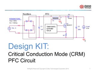
  • 1. Design KIT: Critical Conduction Mode (CRM) PFC Circuit All Rights Reserved Copyright (C) Bee Technologies Corporation 2010 1 Vac, in C1 1uF C2 200u ILoad 0.5A L1 12 Diode D2 Q1 MOSFET R7 L2 1 2 0 0 Rectifiers PFC TB6819AFG Controller Circuit PARAMETERS: f req = 50Hz Vin = 100Vac
  • 2. Contents • Introduction • Application Circuit • Design Specification • Time Scaling • Application Circuit with Time Scaling (tscale =10) • Common Mode Choke Coil for PFC • Design Steps (1-8) • Switching Devices VPEAK and IPEAK at Steady State • Switching Devices VPEAK and IPEAK at Start Up Appendix A.Excel Calculation Sheet B.Simulation Index All Rights Reserved Copyright (C) Bee Technologies Corporation 2012 2
  • 3. Introduction Most electronic ballasts and switching power supplies use a bridge rectifier and a bulk storage capacitor to derive raw dc voltage from the utility ac line, figure above: Vin=100Vac, 50Hz and PO=200W. All Rights Reserved Copyright (C) Bee Technologies Corporation 2012 3 Vin AC_IN1 PARAMETERS: f req = 50Hz Vin = 100Vac AC_IN2 Cbulk 2000uF 0 bulkDB1 DB2DB3 Diode DB4 Load 1.414Adc Iline Vbulk
  • 4. Time 160ms 164ms 168ms 172ms 176ms 180ms 184ms 188ms 192ms 196ms 200ms AVG(ABS(W(Vin)))/(RMS(ABS(V(AC_IN1,AC_IN2)))*RMS(ABS(I(Vin)))) 0 0.2 0.4 0.6 0.8 1.0 ABS( I(Vin) ) 0A 10A 20A ABS( V(AC_IN1,AC_IN2) ) V(bulk) 0V 100V 200V SEL>> Introduction The Uncorrected Power Factor rectifying circuit draws current from the ac line when the ac voltage exceeds the capacitor voltage (Vbulk). The current (Iline) is non- sinusoidal. This results in a poor power factor condition where the apparent input power is much higher than the real power, figure above, power factor ratios of 0.5 to 0.7 are common. All Rights Reserved Copyright (C) Bee Technologies Corporation 2012 4 |VAC, in, 100V| (VPEAK, in=100*2=141.42V) and Vbulk |Iline| Power Factor Ratio = Pin, avg./(Vin, rms* Iin, rms)
  • 5. Vac, in C1 1uF C2 200u ILoad 0.5A L1 12 Diode D2 Q1 MOSFET R7 L2 1 2 0 0 Rectifiers PFC TB6819AFG Controller Circuit PARAMETERS: f req = 50Hz Vin = 100Vac Introduction The Power Factor Correction (PFC) circuit, as an off-line active preconverter, is designed to draw a sinusoidal current from the AC line that is in phase with input voltage. As a result, the power factor ratio is improved to be near to ideal (1). The TB6819AFG is a critical conduction mode (CRM) PFC controller IC. The description including equation and constants as a guide to understand its designing process is included in this document. All Rights Reserved Copyright (C) Bee Technologies Corporation 2012 5 Iline VDC, OUT
  • 6. Time*10 100ms 104ms 108ms 112ms 116ms 120ms 124ms 128ms 132ms 136ms 140ms AVG(ABS(W(Vin))) / (RMS(ABS(V(AC_IN1,AC_IN2)))*RMS(ABS(I(Vin)))) 0 0.2 0.4 0.6 0.8 1.0 -I(Vin) -8.0A 0A 8.0A SEL>> 1 V(AC_IN1,AC_IN2) 2 V(VOUT) -160V 0V 160V 1 200V 400V 600V 2 >> Introduction The poor power factor load is corrected by keeping the ac line current sinusoidal and in phase with the line voltage. This results with power factor ratio is 0.85. All Rights Reserved Copyright (C) Bee Technologies Corporation 2012 6 VAC, in, 100V and VDC, OUT, 400V Iline Power Factor Ratio = 0.85 *simulation result at tscale = 10
  • 7. Load 0.5A R12 39k C9 0.1uF Vin FREQ = {f req} VAMPL = {Vin*1.414} AC_IN1 R4 100 PARAMETERS: f req = 50 Vin = 100 C6 3300p AC_IN2 C1 1u 0 0 R9 3MEG R10 22k C5 10nF C8 47uF IC = 17.9 D5 DZ18V R11 360k R6 68k R8 100k MULT Rtf C3 0.47uF IC = 3.74 L1 {L} 12 PARAMETERS: L = 230u N = {1/9.6} N=N2/N1, L2=(N^2)*L1 VCC V1 R7 0.11 POUT V2 U1 TB6819AFG FB_IN COMP MULT ISZCD GND POUT VCC FB_IN IS ZCD C7 8p R3 10k C4 1uF VOUT R2 1.5MEG R1 9.53k C2 200uF IC = {2.51*1509.53/9.53} COMP L2 {N*N*L} 1 2 K K1 COUPLING = 1 K_Linear L1 = L1 L2 = L2 DB1 Diode D2 Diode D3 Diode D4 DB2DB3 Diode DB4 Q1 MOSFET R5 10 Application Circuit All Rights Reserved Copyright (C) Bee Technologies Corporation 2012 7 VAC, in=85-265VAC PO = 200W, VDC, OUT = 400VDC *Analysis directives: .TRAN 0 20ms 0 100n .OPTIONS ABSTOL= 100n .OPTIONS GMIN= 1.0E-8 .OPTIONS ITL1= 500 .OPTIONS ITL2= 200 .OPTIONS ITL4= 40 .OPTIONS RELTOL= 0.01 .OPTIONS VNTOL= 100u
  • 8. Time 10ms 11ms 12ms 13ms 14ms 15ms 16ms 17ms 18ms 19ms 20ms AVG(ABS(W(Vin)))/(RMS(ABS(V(AC_IN1,AC_IN2)))*RMS(ABS(I(Vin)))) 0 0.5 1.0 Time 0s 2ms 4ms 6ms 8ms 10ms 12ms 14ms 16ms 18ms 20ms -I(Vin) -10A 0A 10A SEL>> 1 V(AC_IN1,AC_IN2) 2 V(VOUT) -200V 0V 200V 1 380V 400V 420V 2 >> Application Circuit All Rights Reserved Copyright (C) Bee Technologies Corporation 2012 8 VAC, in, 100V and VDC, OUT, 400V Iline Power Factor Ratio = 0.85 Total simulation time = 1429.49 seconds
  • 9. Design Specification This application circuit is for 400VDC/200W output Critical Conduction Mode (CRM) PFC Circuit : • VAC, in,min = 85 (VAC) • VAC, in,max = 265 (VAC) • VO = 400 (VDC) • Po = 200 (W) • fs = 20kHz ~ 150kHz, 50kHz •  (assumed) = 90% Control IC : • Part # TTB6819AFG (PFC Controller IC) • Switching Technique: Critical Conduction Mode (CRM) All Rights Reserved Copyright (C) Bee Technologies Corporation 2012 9
  • 10. Time Scaling The transient (cycle-by-cycle) simulation of PFC circuits is really time (and memory) consuming exercise, even with a fast computer. There is a way to speed up simulations by artificially altering some of the key element values by using of time scaling ratio (tscale), passed as a parameter to the simulation engine: • Fline = F line  tscale • C 2 = C 2  tscale • C 3 = C 3  tscale • C 4 = C 4  tscale • C 5 = C 5  tscale All Rights Reserved Copyright (C) Bee Technologies Corporation 2012 10
  • 11. Application Circuit with Time Scaling (tscale =10) All Rights Reserved Copyright (C) Bee Technologies Corporation 2012 11 VAC, in=85-265VAC PO = 200W, VDC, OUT = 400VDC *Analysis directives: .TRAN 0 2ms 0 100n .OPTIONS ABSTOL= 100n .OPTIONS GMIN= 1.0E-8 .OPTIONS ITL1= 500 .OPTIONS ITL2= 200 .OPTIONS ITL4= 40 .OPTIONS RELTOL= 0.01 .OPTIONS VNTOL= 100u Load 0.5A R12 39k C9 0.1uF Vin FREQ = {f req*tscale} VAMPL = {Vin*1.414} AC_IN1 R4 100 PARAMETERS: f req = 50 Vin = 100 C6 3300p AC_IN2 C1 1u 0 0 R9 3MEG R10 22k C5 {10n/tscale} C8 47uF IC = 17.9 D5 DZ18V R11 360k R6 68k R8 100k MULT Rtf C3 {0.47u/tscale} IC = 3.74 L1 {L} 12 PARAMETERS: L = 230u N = {1/9.6} N=N2/N1, L2=(N^2)*L1 VCC V1 R7 0.11 POUT V2 U1 TB6819AFG FB_IN COMP MULT ISZCD GND POUT VCC FB_IN IS ZCD C7 8p R3 10k C4 {1u/tscale} VOUT R2 1.5MEG R1 9.53k C2 {200u/tscale} IC = {2.51*1509.53/9.53} COMP L2 {N*N*L} 1 2 K K1 COUPLING = 1 K_Linear L1 = L1 L2 = L2 DB1 Diode D2 Diode D3 Diode D4 PARAMETERS: tscale = 10 DB2DB3 Diode DB4 Q1 MOSFET R5 10
  • 12. Time*10 10ms 11ms 12ms 13ms 14ms 15ms 16ms 17ms 18ms 19ms 20ms AVG(ABS(W(Vin)))/(RMS(ABS(V(AC_IN1,AC_IN2)))*RMS(ABS(I(Vin)))) 0 0.5 1.0 Time*10 0s 2ms 4ms 6ms 8ms 10ms 12ms 14ms 16ms 18ms 20ms -I(Vin) -10A 0A 10A SEL>> 1 V(AC_IN1,AC_IN2) 2 V(VOUT) -200V 0V 200V 1 380V 400V 420V 2 >> Application Circuit with Time Scaling (tscale =10) All Rights Reserved Copyright (C) Bee Technologies Corporation 2012 12 VAC, in, 100V and VDC, OUT, 400V Iline Power Factor Ratio = 0.85 Total simulation time = 132.41 seconds
  • 13. Common Mode Choke Coil for PFC To model a simple common mode choke coil, the SPICE primitive k, which describes the coupling ratio between L1 and L2, can be used. COUPLING=1 of K_Linear means there is no leakage inductance in the common mode choke coil model. N is a ratio of L2 turns and L1 turns, or N2/N1 Input the parameters: L as an L1 inductance value and N, then L2 is calculated using equation: L2 = N2L1 All Rights Reserved Copyright (C) Bee Technologies Corporation 2012 13 L1 {L} 12 PARAMETERS: L = 230u N = {1/9.6} N=N2/N1, L2=(N^2)*L1 L2 {N*N*L} 1 2 K K1 COUPLING = 1 K_Linear L1 = L1 L2 = L2
  • 14. Design Steps (1-8) (1) Output Voltage and Feedback Circuit (2) Output Capacitor (3) L1 Inductance (4) Input Capacitor (5) Auxiliary Winding L2 (6) Multiplier Input Circuit (MULT) (7) Current Detection Circuit (IS) (8) Zero Current Detection Circuit (ZCD) All Rights Reserved Copyright (C) Bee Technologies Corporation 2012 14
  • 15. (1) Output Voltage and Feedback Circuit The output voltage is resistively divided and applied to the error amplifier, to set the VO the R1 and R2 resistor value should satisfy the following equation : *With VO=400V and R2=1.5M, R1 is calculated to be 9.47k, however a resistor of 9.53k , which is available in the E96 series, is used as R1 (actual). All Rights Reserved Copyright (C) Bee Technologies Corporation 2012 15 2.51 RR RV 21 1O    Output DC Voltage, VO 400 V Error Amplifier Reference Voltage Verr 2.51 V R2 1.5 M R1 9.47 k R1 (actual) 9.53* k
  • 16. (2) Output Capacitor The output capacitance C2 is determined so that the PFC output ripple voltage dose not exceed the VOPV-2, for the capacitor selection, the following equation should be satisfied: The value of VOVP-2, min and Verr, min are inform in the TB6819AFG datasheet. All Rights Reserved Copyright (C) Bee Technologies Corporation 2012 16 PO 200 W fin 50 Hz VO 400 V VOVP-2, min 2.63 V Verr, min 2.46 V C2  41 F C2used 200 F   1-/VVV22 P C2 err2-OVP 2 O O   inf
  • 17. Load 0.5A R12 39k C9 0.1uF Vin FREQ = {f req*tscale} VAMPL = {Vin*1.414} AC_IN1 R4 100 PARAMETERS: f req = 50 Vin = 100 C6 3300p AC_IN2 C1 1u 0 0 R9 3MEG R10 22k C5 {10n/tscale} C8 47uF IC = 17.9 D5 DZ18V R11 360k R6 68k R8 100k MULT Rtf C3 {0.47u/tscale} IC = 3.74 L1 {L} 12 PARAMETERS: L = 230u N = {1/9.6} N=N2/N1, L2=(N^2)*L1 VCC V1 R7 0.11 POUT V2 U1 TB6819AFG FB_IN COMP MULT ISZCD GND POUT VCC FB_IN ISZCD C7 8p R3 10k C4 {1u/tscale} VOUT R2 1.5MEG R1 9.53k C2 {200u/tscale} IC = {2.51*1509.53/9.53} PARAMETERS: tscale = 10 COMP L2 {N*N*L} 1 2 K K1 COUPLING = 1 K_Linear L1 = L1 L2 = L2 DB1 Diode D2 Diode D3 Diode D4 DB2DB3 Diode DB4 Q1 MOSFET R5 10 Simulation of Step (1) and (2) All Rights Reserved Copyright (C) Bee Technologies Corporation 2012 17 Vin = 100Vac with frequency 50Hz, tscale = 10 R1=9.53k and R2=1.5M Iload = 0.5A as PO=200W at VO=400V C2 = 200F *Analysis directives: .TRAN 0 4ms 0 100n .OPTIONS ABSTOL= 100n .OPTIONS GMIN= 1.0E-8 .OPTIONS ITL1= 500 .OPTIONS ITL2= 200 .OPTIONS ITL4= 40 .OPTIONS RELTOL= 0.01 .OPTIONS VNTOL= 100u
  • 18. Time*10 0s 5ms 10ms 15ms 20ms 25ms 30ms 35ms 40ms V(FB_IN) 2.63 2.46 2.4 2.6 2.8 V(VOUT) 380V 400V 420V SEL>> V(AC_IN1,AC_IN2) -200V 0V 200V Simulation of Step (1) and (2) All Rights Reserved Copyright (C) Bee Technologies Corporation 2012 18 VAC, in,=100V (VPEAK, in,=100*1.4142=141.4V) V(FB IN), VOVP-2, min.(2.63V), and Verr,min(2.46V) VO=400Vdc with 2fline ripple Total simulation time = 270.61 seconds
  • 19. (3) L1 Inductance The switching frequencyfs (Hz) depends on the L1 inductance and input/output condition which the equation and the calculation data are as shown below. *The fs value should be within 20kHz and 150kHz, to avoid an occurrence of EMI problem, fs=50kHz is used. All Rights Reserved Copyright (C) Bee Technologies Corporation 2012 19 OO 2 minin,AC,minin,AC,O PVfs1002 V)V2(V L1    η Output DC Voltage, VO 400 V Minimum AC Input Voltage, VAC, in, min 85 V Power Efficiency,  (assumed) 90 % Switching Frequency, fs* 50 kHz Output Power, PO 200 W Calculated Inductance, L1(calculated) 227 H Selected (Actual) Inductance, L1(actual) 230 H
  • 20. (4) Input Capacitor C1 should be capable of supplying energy stored in the L1 while the FET is on. Assumed that the on/off duty is 50%, the C1 should be temporarily able to supply twice the current. A current reaches its maximum at the VAC, in, min. Thus, the following relationship should be satisfied: All Rights Reserved Copyright (C) Bee Technologies Corporation 2012 20 L1 230 H PO 200 W VAC, in, min 85 V C1  0.35 F C1used 1 F 4 minin,AC, 2 O V PL12 C1  
  • 21. Load 0.5A R12 39k C9 0.1uF Vin FREQ = {f req*tscale} VAMPL = {Vin*1.414} AC_IN1 R4 100 PARAMETERS: f req = 50 Vin = 85 C6 3300p AC_IN2 C1 1u 0 0 R9 3MEG R10 22k C5 {10n/tscale} C8 47uF IC = 17.9 D5 DZ18V R11 360k R6 68k R8 100k MULT Rtf C3 {0.47u/tscale} IC = 4.22 L1 {L} 12 PARAMETERS: L = 230u N = {1/9.6} N=N2/N1, L2=(N^2)*L1 VCC V1 R7 0.11 POUT V2 U1 TB6819AFG FB_IN COMP MULT ISZCD GND POUT VCC FB_IN ISZCD C7 8p R3 10k C4 {1u/tscale} VOUT R2 1.5MEG R1 9.53k C2 {200u/tscale} IC = {2.51*1509.53/9.53} PARAMETERS: tscale = 10 COMP L2 {N*N*L} 1 2 K K1 COUPLING = 1 K_Linear L1 = L1 L2 = L2 DB1 Diode D2 Diode D3 Diode D4 DB2DB3 Diode DB4 Q1 MOSFET R5 10 Simulation of Step (3) and (4) All Rights Reserved Copyright (C) Bee Technologies Corporation 2012 21 Vin, min = 85Vac with frequency 50Hz, tscale = 10 Iload = 0.5A as PO=200W at VO=400V The Calculated L1 value 227H (adjusted 230H is used) I(L1) C1 = 1F *Analysis directives: .TRAN 0 20ms 16m 100n .OPTIONS ABSTOL= 100n .OPTIONS GMIN= 1.0E-8 .OPTIONS ITL1= 500 .OPTIONS ITL2= 200 .OPTIONS ITL4= 40 .OPTIONS RELTOL= 0.01 .OPTIONS VNTOL= 100u
  • 22. Time 16.45ms 16.46ms 16.47ms 16.48ms 16.49ms 16.50ms 16.51ms 16.52ms 16.53ms 16.54ms 16.55ms V(POUT) 0V 10V 20V -I(L1) 0A 5A 10A V(VOUT) 395V 400V 405V SEL>> Simulation of Step (3) and (4) All Rights Reserved Copyright (C) Bee Technologies Corporation 2012 22 VO=400Vdc with high switching ripple I(L1) Switching Control Signal, fs = 48.4 kHz Total simulation time = 976.83 seconds
  • 23. (5) Auxiliary Winding L2 The auxiliary winding L2 is used to detect the zero inductor current condition of the inductor L1. Since the maximum reference voltage for the ZCD comparator is 1.9V (the IC specification) , N1/N2 should meet the following condition: Where N1 is the number of winding of turns of L1, N2 is that of L2 *To ensure that the design requirements are met, N1/N2 should preferably about 10 (9.6 is used) to allow for design margins. All Rights Reserved Copyright (C) Bee Technologies Corporation 2012 23 9.1 maxin,AC,O V2V N1/N2   Output DC Voltage, VO 400 V Maximum AC Input Voltage, VAC, in, max 265 V Calculated Turn Number Ratio, N1/N2 < 14 Selected Transformer Turn Ratio, N1/N2 (actual) 9.6*
  • 24. Load 0.5A R12 39k C9 0.1uF Vin FREQ = {f req*tscale} VAMPL = {Vin*1.414} AC_IN1 R4 100 PARAMETERS: f req = 50 Vin = 265 C6 3300p AC_IN2 C1 1u 0 0 R9 3MEG R10 22k C5 {10n/tscale} C8 47uF IC = 17.9 D5 DZ18V R11 360k R6 68k R8 100k MULT Rtf C3 {0.47u/tscale} IC = 2.533 L1 {L} 12 PARAMETERS: L = 230u N = {1/9.6} N=N2/N1, L2=(N^2)*L1 VCC V1 R7 0.11 POUT V2 U1 TB6819AFG FB_IN COMP MULT ISZCD GND POUT VCC FB_IN ISZCD C7 8p R3 10k C4 {1u/tscale} VOUT R2 1.5MEG R1 9.53k C2 {200u/tscale} IC = {2.51*1509.53/9.53} PARAMETERS: tscale = 10 COMP L2 {N*N*L} 1 2 K K1 COUPLING = 1 K_Linear L1 = L1 L2 = L2 DB1 Diode D2 Diode D3 Diode D4 DB2DB3 Diode DB4 Q1 MOSFET R5 10 Simulation of Step (5) All Rights Reserved Copyright (C) Bee Technologies Corporation 2012 24 N1/N2=9.6, input parameter N = N2/N1 = 1/9.6 I(L1) Vin, min = 265Vac with frequency 50Hz, tscale = 10 Iload = 0.5A as PO=200W at VO=400V *Analysis directives: .TRAN 0 4ms 2ms 100n .OPTIONS ABSTOL= 100n .OPTIONS GMIN= 1.0E-8 .OPTIONS ITL1= 500 .OPTIONS ITL2= 200 .OPTIONS ITL4= 40 .OPTIONS RELTOL= 0.01 .OPTIONS VNTOL= 100u
  • 25. Time*10 20ms 22ms 24ms 26ms 28ms 30ms 32ms 34ms 36ms 38ms 40ms V(ZCD) 1.9 0 2.5 5.0 7.5 -I(L1) 0A 2.5A 5.0A V(VOUT) 375V 400V 425V SEL>> V(AC_IN1,AC_IN2) -400V 0V 400V Simulation of Step (5) All Rights Reserved Copyright (C) Bee Technologies Corporation 2012 25 VO=400V and PO=200W VAC, in, min=265V (VPEAK, in, min=265*1.4142=374.8V) I(L1) V(ZCD) and the maximum reference voltage of the TB6819AFG’s ZCD comparator, 1.9V Total simulation time = 1012.86 seconds
  • 26. (6) Multiplier Input Circuit (MULT) The AC input supply voltage (sinewave) is applied to the multiplier by dividing a full-wave rectified voltage waveform. The IC startup threshold voltages of the Brown Out Protection (BOP) function = 0.75V and the MULT linear input voltage range of the multiplier = 0 to 3V, the R9 and R10 resistor should satisfy the following condition: with excel calculation sheet PFC_Cal-Sht.xlsx you can input R9 and R10 values, then check the calculated BOP and Linear MULT values to be within the maximum values. All Rights Reserved Copyright (C) Bee Technologies Corporation 2012 26 109 10minin,AC, RR R2V 0   75. Maximum AC Input Voltage, VAC, in, min 400 V Maximum AC Input Voltage, VAC, in, max 265 V R9 3 M R10 22 k Minimum Condition for BOP 0.875 > 0.75 Maximum Condition for Linear MULT 2.728 < 3 3   109 10maxin,AC, RR R2V and
  • 27. Load 0.5A R12 39k C9 0.1uF Vin FREQ = {f req*tscale} VAMPL = {Vin*1.414} AC_IN1 R4 100 PARAMETERS: f req = 50 Vin = 265 C6 3300p AC_IN2 C1 1u 0 0 R9 3MEG R10 22k C5 {10n/tscale} C8 47uF IC = 17.9 D5 DZ18V R11 360k R6 68k R8 100k MULT Rtf C3 {0.47u/tscale} IC = 2.533 L1 {L} 12 PARAMETERS: L = 230u N = {1/9.6} N=N2/N1, L2=(N^2)*L1 VCC V1 R7 0.11 POUT V2 U1 TB6819AFG FB_IN COMP MULT ISZCD GND POUT VCC FB_IN ISZCD C7 8p R3 10k C4 {1u/tscale} VOUT R2 1.5MEG R1 9.53k C2 {200u/tscale} IC = {2.51*1509.53/9.53} PARAMETERS: tscale = 10 COMP L2 {N*N*L} 1 2 K K1 COUPLING = 1 K_Linear L1 = L1 L2 = L2 DB1 Diode D2 Diode D3 Diode D4 DB2DB3 Diode DB4 Q1 MOSFET R5 10 Simulation of Step (6) at Vin, max All Rights Reserved Copyright (C) Bee Technologies Corporation 2012 27 Vin, max = 265Vac with frequency 50Hz, tscale = 10 Iload = 0.5A as PO=200W at VO=400V R10=3M and R11=22k*Analysis directives: .TRAN 0 4ms 2ms 100n .OPTIONS ABSTOL= 100n .OPTIONS GMIN= 1.0E-8 .OPTIONS ITL1= 500 .OPTIONS ITL2= 200 .OPTIONS ITL4= 40 .OPTIONS RELTOL= 0.01 .OPTIONS VNTOL= 100u
  • 28. Time*10 20ms 22ms 24ms 26ms 28ms 30ms 32ms 34ms 36ms 38ms 40ms V(MULT) 3 0 1.0 2.0 3.0 4.0 V(Rtf) 0V 100V 200V 300V 400V V(AC_IN1,AC_IN2) -400V -200V 0V 200V 400V SEL>> Simulation of Step (6) at Vin, max All Rights Reserved Copyright (C) Bee Technologies Corporation 2012 28 Full-wave rectified voltage VAC, in, max=265V (VPEAK, in, min=265*1.4142=374.8V) V(MULT) < MULT linear input maximum voltage (3V) Total simulation time = 1012.86 seconds
  • 29. Load 0.5A R12 39k C9 0.1uF Vin FREQ = {f req*tscale} VAMPL = {Vin*1.414} AC_IN1 R4 100 PARAMETERS: f req = 50 Vin = 85 C6 3300p AC_IN2 C1 1u 0 0 R9 3MEG R10 22k C5 {10n/tscale} C8 47uF IC = 17.9 D5 DZ18V R11 360k R6 68k R8 100k MULT Rtf C3 {0.47u/tscale} IC = 4.22 L1 {L} 12 PARAMETERS: L = 230u N = {1/9.6} N=N2/N1, L2=(N^2)*L1 VCC V1 R7 0.11 POUT V2 U1 TB6819AFG FB_IN COMP MULT ISZCD GND POUT VCC FB_IN ISZCD C7 8p R3 10k C4 {1u/tscale} VOUT R2 1.5MEG R1 9.53k C2 {200u/tscale} IC = {2.51*1509.53/9.53} PARAMETERS: tscale = 10 COMP L2 {N*N*L} 1 2 K K1 COUPLING = 1 K_Linear L1 = L1 L2 = L2 DB1 Diode D2 Diode D3 Diode D4 DB2DB3 Diode DB4 Q1 MOSFET R5 10 Simulation of Step (6) at Vin, min All Rights Reserved Copyright (C) Bee Technologies Corporation 2012 29 R10=3M and R11=22k Vin, min = 85Vac with frequency 50Hz, tscale = 10 Iload = 0.5A as PO=200W at VO=400V *Analysis directives: .TRAN 0 20ms 16m 100n .OPTIONS ABSTOL= 100n .OPTIONS GMIN= 1.0E-8 .OPTIONS ITL1= 500 .OPTIONS ITL2= 200 .OPTIONS ITL4= 40 .OPTIONS RELTOL= 0.01 .OPTIONS VNTOL= 100u
  • 30. Time*10 180ms 182ms 184ms 186ms 188ms 190ms 192ms 194ms 196ms 198ms 200ms V(MULT) 0.75 0 0.5 1.0 V(Rtf) 0V 40V 80V 120V SEL>> V(AC_IN1,AC_IN2) -200V 0V 200V Simulation of Step (6) at Vin, min All Rights Reserved Copyright (C) Bee Technologies Corporation 2012 30 Full-wave rectified voltage VAC, in, min=85V (VPEAK, in, min=85*1.4142=120.2V) V(MULT) > BOP threshold voltage (0.75V) Total simulation time = 976.83 seconds
  • 31. (7) Current Detection Circuit (IS) Iq1 (power switch current) is converted into voltage by R7, then applied to the IS pin. The R7 resistor value calculation follows these steps: 1) The maximum current of the Q1 current, Iq1 (max) should allow the output power PO to meet the specification. Therefore, the following equation should be satisfied: 2) the IS pin peak voltage (Visp) is calculated using the following equation: 3) R7 = Visp / Iq1(max.). All Rights Reserved Copyright (C) Bee Technologies Corporation 2012 31 R10R9 R102V0.65 Visp minin,AC,    Minimum ac input voltage, VAC, in, min 85 V Output power, PO 200 W Power efficiency,  (assumed) 90 % R9 3 M R10 22 k Power switch current, Iq1(max.) 5.23 A TB6819AFG IS pin peak voltage Visp 0.57 V R7 0.11  )2V(η 22100P Iq1(max.) minin,AC, O   
  • 32. Load 0.5A R12 39k C9 0.1uF Vin FREQ = {f req*tscale} VAMPL = {Vin*1.414} AC_IN1 R4 100 PARAMETERS: f req = 50 Vin = 85 C6 3300p AC_IN2 C1 1u 0 0 R9 3MEG R10 22k C5 {10n/tscale} C8 47uF IC = 17.9 D5 DZ18V R11 360k R6 68k R8 100k MULT Rtf C3 {0.47u/tscale} IC = 4.22 L1 {L} 12 PARAMETERS: L = 230u N = {1/9.6} N=N2/N1, L2=(N^2)*L1 VCC V1 R7 0.11 POUT V2 U1 TB6819AFG FB_IN COMP MULT ISZCD GND POUT VCC FB_IN ISZCD C7 8p R3 10k C4 {1u/tscale} VOUT R2 1.5MEG R1 9.53k C2 {200u/tscale} IC = {2.51*1509.53/9.53} PARAMETERS: tscale = 10 COMP L2 {N*N*L} 1 2 K K1 COUPLING = 1 K_Linear L1 = L1 L2 = L2 DB1 Diode D2 Diode D3 Diode D4 DB2DB3 Diode DB4 Q1 MOSFET R5 10 Simulation of Step (7) All Rights Reserved Copyright (C) Bee Technologies Corporation 2012 32 Iq1 R7 = 0.11 Vin, min = 85Vac with frequency 50Hz, tscale = 10 Iload = 0.5A as PO=200W at VO=400V R10=3M and R11=22k*Analysis directives: .TRAN 0 20ms 16m 100n .OPTIONS ABSTOL= 100n .OPTIONS GMIN= 1.0E-8 .OPTIONS ITL1= 500 .OPTIONS ITL2= 200 .OPTIONS ITL4= 40 .OPTIONS RELTOL= 0.01 .OPTIONS VNTOL= 100u
  • 33. Simulation of Step (7) All Rights Reserved Copyright (C) Bee Technologies Corporation 2012 33 Time*10 180ms 182ms 184ms 186ms 188ms 190ms 192ms 194ms 196ms 198ms 200ms V(IS) 0V 0.5V 1.0V ID(Q1) 0A 2.0A 4.0A 6.0A 8.0A SEL>> V(MULT) 0V 0.5V 1.0V Iq1 V(MULT) V(IS) Total simulation time = 976.83 seconds
  • 34. (8) Zero Current Detection Circuit (ZCD) The auxiliary winding L2 is connected to the ZCD pin. The current through L2 is limited to ZCD pin rated current (3mA) by using the current limiting resistor R6. The following relationship should be satisfied depending on whether the external FET is on or off: FET = On: FET = Off: A resistor of 68k is used for limiting the current to 1/5 of the rated current All Rights Reserved Copyright (C) Bee Technologies Corporation 2012 34 VAC, in, max 265 V N2/N1 1/9.6 W VO 400 V FET = ON, R6 > 13.0 k FET = OFF, R6 > 13.9 k R6 (actual) 68 k   3mA N2/N12V R6 max.in,AC,     3mA N2/N1V R6 O  
  • 35. Load 0.5A R12 39k C9 0.1uF Vin FREQ = {f req*tscale} VAMPL = {Vin*1.414} AC_IN1 R4 100 PARAMETERS: f req = 50 Vin = 265 C6 3300p AC_IN2 C1 1u 0 0 R9 3MEG R10 22k C5 {10n/tscale} C8 47uF IC = 17.9 D5 DZ18V R11 360k R6 68k R8 100k MULT Rtf C3 {0.47u/tscale} IC = 2.533 L1 {L} 12 PARAMETERS: L = 230u N = {1/9.6} N=N2/N1, L2=(N^2)*L1 VCC V1 R7 0.11 POUT V2 U1 TB6819AFG FB_IN COMP MULT ISZCD GND POUT VCC FB_IN ISZCD C7 8p R3 10k C4 {1u/tscale} VOUT R2 1.5MEG R1 9.53k C2 {200u/tscale} IC = {2.51*1509.53/9.53} PARAMETERS: tscale = 10 COMP L2 {N*N*L} 1 2 K K1 COUPLING = 1 K_Linear L1 = L1 L2 = L2 DB1 Diode D2 Diode D3 Diode D4 DB2DB3 Diode DB4 Q1 MOSFET R5 10 Simulation of Step (8) All Rights Reserved Copyright (C) Bee Technologies Corporation 2012 35 ON/OFF R6 = 68k Vin, max = 265Vac with frequency 50Hz, tscale = 10 Iload = 0.5A as PO=200W at VO=400V R10=3M and R11=22k*Analysis directives: .TRAN 0 4ms 2ms 100n .OPTIONS ABSTOL= 100n .OPTIONS GMIN= 1.0E-8 .OPTIONS ITL1= 500 .OPTIONS ITL2= 200 .OPTIONS ITL4= 40 .OPTIONS RELTOL= 0.01 .OPTIONS VNTOL= 100u
  • 36. Time*10 20ms 22ms 24ms 26ms 28ms 30ms 32ms 34ms 36ms 38ms 40ms I(R6) 3m/5 -1.0m 0 1.0m V(VOUT) 375V 400V 425V V(AC_IN1,AC_IN2) -400V 0V 400V SEL>> Simulation of Step (8) All Rights Reserved Copyright (C) Bee Technologies Corporation 2012 36 VAC, in, max=265V V(VOUT) I(R6) and 1/5 of the ZCD rated current (3mA/5) Total simulation time = 1012.86 seconds
  • 37. Load 0.5A R12 39k C9 0.1uF Vin FREQ = {f req*tscale} VAMPL = {Vin*1.414} AC_IN1 R4 100 PARAMETERS: f req = 50 Vin = 85 C6 3300p AC_IN2 C1 1u 0 0 R9 3MEG R10 22k C5 {10n/tscale} C8 47uF IC = 17.9 D5 DZ18V R11 360k R6 68k R8 100k MULT Rtf C3 {0.47u/tscale} IC = 4.22 L1 {L} 12 PARAMETERS: L = 230u N = {1/9.6} N=N2/N1, L2=(N^2)*L1 VCC V1 R7 0.11 POUT V2 U1 TB6819AFG FB_IN COMP MULT ISZCD GND POUT VCC FB_IN ISZCD C7 8p R3 10k C4 {1u/tscale} VOUT R2 1.5MEG R1 9.53k C2 {200u/tscale} IC = {2.51*1509.53/9.53} PARAMETERS: tscale = 10 COMP L2 {N*N*L} 1 2 K K1 COUPLING = 1 K_Linear L1 = L1 L2 = L2 DB1 Diode D2 Diode D3 Diode D4 DB2DB3 Diode DB4 Q1 MOSFET R5 10 Switching Devices VPEAK and IPEAK at Steady State All Rights Reserved Copyright (C) Bee Technologies Corporation 2012 37 Vin, min = 85Vac with frequency 50Hz, tscale = 10 Iload = 0.5A as PO=200W at VO=400V I(D2) Switching Diode, D2 *Analysis directives: .TRAN 0 20ms 16m 100n .OPTIONS ABSTOL= 100n .OPTIONS GMIN= 1.0E-8 .OPTIONS ITL1= 500 .OPTIONS ITL2= 200 .OPTIONS ITL4= 40 .OPTIONS RELTOL= 0.01 .OPTIONS VNTOL= 100u ID(Q1) Switching MOSFET, Q1
  • 38. Time 18.00ms 18.25ms 18.50ms 18.75ms 19.00ms 19.25ms 19.50ms 19.75ms 20.00ms ID(Q1) -6A 0A 6A 12A V(Q1:d,Q1:s) 0V 200V 400V 600V I(D2) 8A 16A -2A SEL>> V(D2:2,D2:1) 0V 200V 400V 600V Switching Devices VPEAK and IPEAK at Steady State All Rights Reserved Copyright (C) Bee Technologies Corporation 2012 38 D2 VKA, Peak ≈ 400V at steady state Total simulation time = 976.83 seconds D2 IF, Peak ≈ 12A at steady state Q1 VDS, Peak ≈ 400V at steady state Q1 ID, Peak ≈ 7.2A at steady state
  • 39. Load 0.5A R12 39k C9 0.1uF Vin FREQ = {f req*tscale} VAMPL = {Vin*1.414} AC_IN1 R4 100 PARAMETERS: f req = 50 Vin = 85 C6 3300p AC_IN2 C1 1u 0 0 R9 3MEG R10 22k C5 {10n/tscale} C8 47uF IC = 17.9 D5 DZ18V R11 360k R6 68k R8 100k MULT Rtf C3 {0.47u/tscale} L1 {L} 12 PARAMETERS: L = 230u N = {1/9.6} N=N2/N1, L2=(N^2)*L1 VCC V1 R7 0.11 POUT V2 U1 TB6819AFG FB_IN COMP MULT ISZCD GND POUT VCC FB_IN ISZCD C7 8p R3 10k C4 {1u/tscale} VOUT R2 1.5MEG R1 9.53k C2 {200u/tscale} PARAMETERS: tscale = 40 COMP L2 {N*N*L} 1 2 K K1 COUPLING = 1 K_Linear L1 = L1 L2 = L2 DB1 Diode D2 Diode D3 Diode D4 DB2DB3 Diode DB4 Q1 MOSFET R5 10 Switching Devices VPEAK and IPEAK at Start Up All Rights Reserved Copyright (C) Bee Technologies Corporation 2012 39 Vin, min = 85Vac with frequency 50Hz, tscale = 40 Iload = 0.5A as PO=200W at VO=400V I(D2) Switching Diode, D2 *Analysis directives: .TRAN 0 10ms 0m 100n .OPTIONS ABSTOL= 100n .OPTIONS GMIN= 1.0E-8 .OPTIONS ITL1= 500 .OPTIONS ITL2= 200 .OPTIONS ITL4= 40 .OPTIONS RELTOL= 0.01 .OPTIONS VNTOL= 100u ID(Q1) Switching MOSFET, Q1 Rectifier Diode, DB1-4
  • 40. Time*40 0s 40ms 80ms 120ms 160ms 200ms 240ms 280ms 320ms 360ms 400ms 1 V(Q1:d,Q1:s) 2 ID(Q1) -500V 0V 500V 1 -10A 0A 10A 2 >> 1 V(D2:2,D2:1) 2 I(D2) 0V 200V 400V 600V 1 SEL>> 0A 6A 12A 18A 2 SEL>> 1 V(DB1:2,DB1:1) 2 I(DB1) 100V 200V -10V 1 >> 0A 8A 16A 2 V(VOUT) 0V 200V 400V 600V Switching Devices VPEAK and IPEAK at Start Up All Rights Reserved Copyright (C) Bee Technologies Corporation 2012 40 V(VOUT) at start up Total simulation time = 733.5 seconds D2 VKA, Peak ≈ 400V and IF, Peak ≈ 16A at start up Q1 VDS, Peak ≈ 400V and ID, Peak ≈ 10A at start up DB1-4 IF, Peak ≈ 10A at start up
  • 41. Load 0.5A R12 39k Q2 2SK2611 C9 0.1uF Vin FREQ = {f req*tscale} VAMPL = {Vin*1.414} AC_IN1 R4 100 PARAMETERS: f req = 50 Vin = 100 C6 3300p AC_IN2 C1 1u 0 0 R9 3MEG R10 22k C5 {10n/tscale} C8 47uF IC = 17.9 D5 DZ18V R11 360k R6 68k R8 100k MULT Rtf C3 {0.47u/tscale} IC = 3.74 L1 {L} 12 PARAMETERS: L = 230u N = {1/9.6} N=N2/N1, L2=(N^2)*L1 VCC V1 R7 0.11 POUT V2 U1 TB6819AFG FB_IN COMP MULT ISZCD GND POUT VCC FB_IN ISZCD C7 8p R3 10k C4 {1u/tscale} VOUT R2 1.5MEG R1 9.53k COMP L2 {N*N*L} 1 2 K K1 COUPLING = 1 K_Linear L1 = L1 L2 = L2 C2 RJJ-35V221MG5-T20 D2 SCS110AG DB1 Diode D3 Diode D4 PARAMETERS: tscale = 10 DB2DB3 Diode DB4 R5 10 Simulation with Models from the SpicePark (1/4) All Rights Reserved Copyright (C) Bee Technologies Corporation 2012 41 Capacitor model MOSFET professional model Schottky diode model Replace some default model with models from SpicePark *Analysis directives: .TRAN 0 2ms 0 100n .OPTIONS ABSTOL= 100n .OPTIONS GMIN= 1.0E-8 .OPTIONS ITL1= 500 .OPTIONS ITL2= 200 .OPTIONS ITL4= 100 .OPTIONS RELTOL= 0.01 .OPTIONS VNTOL= 100u
  • 42. Time 484us 488us 492us 496us 500us 504us 508us 512us 516us 520us 524us V(V2) 0V 40V -I(L1) 0A 5A 10A V(V1) 0V 250V 500V V(Q2:g) 10V 20V SEL>> Time 0s 0.2ms 0.4ms 0.6ms 0.8ms 1.0ms 1.2ms 1.4ms 1.6ms 1.8ms 2.0ms V(VOUT) 392V 400V Simulation with Models from the SpicePark (2/4) All Rights Reserved Copyright (C) Bee Technologies Corporation 2012 42 V(VOUT) with high frequency ripple which is caused by ESR and ESL of the capacitor model. Gate charge characteristics is include in the MOSFET Professional model. V(V1) I (L1) V(V2) Total simulation time = 408.13 seconds
  • 43. Time 476us 480us 484us 488us 492us 496us 500us 504us 508us 512us 516us V(V2) 0V 40V -I(L1) 0A 5A 10A V(V1) 0V 250V 500V V(Q1:g) 10V 20V SEL>> Time 0s 0.5ms 1.0ms 1.5ms 2.0ms V(VOUT) 392V 400V Simulation with Models from the SpicePark (3/4) All Rights Reserved Copyright (C) Bee Technologies Corporation 2012 43 The Simulation Waveform with the defaults models V(V1) I (L1) V(V2) V(VOUT) without high frequency ripple which is caused by ESR and ESL of the capacitor model. Gate charge characteristics is not include in the default model. Total simulation time = 132.41 seconds
  • 44. Simulation with Models from the SpicePark (1/4) All Rights Reserved Copyright (C) Bee Technologies Corporation 2012 44 SpicePark of MOSFET model Select the device which is capable of handling the simulated peak values.
  • 45. Excel Calculation Sheet (1/2) All Rights Reserved Copyright (C) Bee Technologies Corporation 2012 45 Design Specification VAC, in,min 85 V VAC, in,max 265 V fin 50 Hz VO 400 V PO 200 W fs 50 kHz  (assumed) 90 % (1) Output Voltage & Feedback Circuit R2 1.5 M ; Input R2 value, the R1 for the VO specification is auto-calculatedR1 9.47 k R1 (actual) 9.53 k (2) Output Capacitor VOVP-2, MIN. 2.63 V ; VOVP-2, MIN. and Verr, MIN. are TB6819AFG electrical characteristicsVerr, MIN. 2.46 V C2 ³ 41 uF (3) L1 Inductance L1 227 mH L1(actual) 230 mH
  • 46. Excel Calculation Sheet (2/2) All Rights Reserved Copyright (C) Bee Technologies Corporation 2012 46 (4) Input Capacitor C1 ³ 0.35 F C1(actual) 1 F (5) Auxiliary Winding L2 N1/N2 < 14 N1/N2(actual) 9.6 (6) Multiplier Input Circuit (MULT) R9 3 M ; Input R9 and R10 values, then check the BOP and the Linear MULT valuesR10 22 k Codition: BOP 0.875 > 0.75 Linear MULT 2.728 < 3 (7) Current Detection Circuit (IS) Iq1(max.) 5.23 A Visp 0.57 V R7 0.11  (8) Zero Current Detection Circuit (ZCD) FET=ON, R8 > 13.0 k FET=OFF, R8 > 13.9 k R8 (actual) 68 k ; limiting the current to 1/5 of the rated current. Remark Input your design specification and your selected parameters. The numbers in the green font are auto- calculated numbers. The numbers in the blue font are the design actual selected (used) number.
  • 47. Simulation Index All Rights Reserved Copyright (C) Bee Technologies Corporation 2012 47 Simulations Folder name 1. Application Circuit....................................................................... 2. Application Circuit with Time Scaling (tscale =10)......................... 3. Simulation of Step (1) and (2)..................................................... 4. Simulation of Step (3) and (4)..................................................... 5. Simulation of Step (5)................................................................. 6. Simulation of Step (6) at Vin, max.................................................. 7. Simulation of Step (6) at Vin, min................................................... 8. Simulation of Step (7)................................................................. 9. Simulation of Step (8)................................................................. 10. Switching Devices VPEAK and IPEAK at Steady State................... 11. Switching Devices VPEAK and IPEAK at Start Up........................... APPCKT APPCKT_tscale STEP1-2 STEP3-4 STEP5 STEP6_INMAX STEP6_INMIN STEP7 STEP8 IVPEAK-SS IVPEAK-SU Libraries : 1. ..¥part¥tb6819afg¥tb6819afg.lib 2. ..¥part¥parts.lib