

Recommended
More Related Content
What's hot
What's hot (13)
Viewers also liked
Viewers also liked (20)
Similar to Sit electrico
Similar to Sit electrico (20)
More from Silvio roman
More from Silvio roman (20)
Recently uploaded
Recently uploaded (20)
Sit electrico
- 1. 4-3 GROUP 2 ELECTRICAL CIRCUIT (up to #1000) 21074EC01 ¡⁄ Machine serial no : up to #0179
- 2. 4-3-1 21074EC01A ¡⁄ Machine serial no : #0180~#1000
- 3. 4 -4 1. POWER CIRCUIT (up to #0179) The negative terminal of battery is grounded to the machine chassis through master switch. When the start switch is in the OFF position, the current flows from the positive battery terminal as shown below. OPERATING FLOW Battery Battery relay Reset button[CS-61] Fuse box [No.1] I/conn [CN-8(12)] Start switch [CS-2(1)] Power relay [CR-35(30)] Fuse box [No.2] I/conn [CN-10(6)] Room lamp [CL-1(2)] Door switch[CS-1] Cassette radio [CN-27(11)] Fuse box [No.3] I/conn [CN-11(4)] AC&Heater controller [CN-116(3,4)] Fuse box [No.4] I/conn [CN - 5(4)] I/conn [CN -17(5)] Wiper motor Controller [CN-141(7)] Wiper motor [CN-21(4)] Fuse box [No.5] CPU controller [CN-50(7)] Fuse box [No.6] I/conn [CN-11(5)] Relay(Hi, M2) Engine Start switch Check point Voltage 1) ¡ GND : Ground OFF OFF - GND (Battery 1 EA) - GND (Battery 2 EA) - GND (Battery 2 EA) - GND (Reset button) 10~12.5V 20~25V 20~25V 20~25V 2) CHECK POINT I/conn : Intermediate connector
- 4. 4-5 POWER CIRCUIT(up to #0179) 21074EL03
- 5. 4 -5-1 1. POWER CIRCUIT (from #0180 to #1000) The negative terminal of battery is grounded to the machine chassis through master switch. When the start switch is in the OFF position, the current flows from the positive battery terminal as shown below. OPERATING FLOW Battery Battery relay Fusible link¡†CN-60¡‡ Fuse box¡†No.1¡‡ l/conn¡†CN-8(12)¡‡ Start switch¡†CS-2(1)¡‡ Power relay¡†CR-35(30)] Fuse box¡†No.2¡‡ I/conn¡†CN-10(6)¡‡ Room lamp¡†CL-1(2)¡‡ Door switch¡†CS-1¡‡ Cassette radio¡†CN-27(11)¡‡ Fuse box¡†No.3¡‡ l/conn¡†CN-11(4)¡‡ AC & Heater controller¡†CN -116(3, 4)¡‡ Fuse box¡†No.4¡‡ I/conn¡†CN - 5(4)¡‡ I/conn¡†CN -17(5)¡‡ Wiper motor controller ¡†CN-141(7)¡‡ Wiper motor¡†CN-21(4)¡‡ Fuse box¡†No.5¡‡ CPU controller¡†CN-50(7)¡‡ Fuse box¡†No.6¡‡ I/conn¡†CN-11(5)¡‡ Relay(Hi, M2) ¡ I/conn : Intermediate connector CHECK POINT Engine Start switch Check point Voltage 1) 2) ¡ GND : Ground OFF OFF ¤ - GND (Battery 1EA) ¤Ł- GND (Battery 2EA) ¤Ø- GND (Battery 2EA) ¤Œ - GND (Fusible link) 10~12.5V 20~25V 20~25V 20~25V
- 6. 4-5-2 POWER CIRCUIT (from #0180 to #1000) 21074EL03A
- 7. 2. STARTING CIRCUIT(up to #1000) OPERATING FLOW Battery(+) terminal Battery relay[CR-1] Reset button[CS-61] Fuse box [No.1] I/conn [CN-8(12)] Start key [CS-2(1)] ¡ Start switch : ON Start switch ON [CS-2(2)] I/conn [CN-8(11)] Diode[DO-2] Battery relay [CR-1]:Battery relay operating(All power is supplied with the electric component) Start switch ON [CS-2(3)] I/conn [CN-8(10)] Power relay [CR-35(86)¡ (87)] Fuse box [No.12] I/conn [CN-1(5)] Fuel cut-off [CN-79(1)] ¡ Start switch : START Start switch START[CS-2(5)] I/conn[CN-8(9)] Safety relay [CR-5(86) ¡ (30)] I/conn [CN-3(4)] Start relay [CR-23] I/conn [CN-1(4)] Fuel cut off [CN-79(2)] 4 -6 Engine Start switch Check point Voltage ¤ -GND (Battery) ¤ Ł -GND (Start key) ¤ Ø -GND (Battery relay M4) Operating Start ¤ Œ -GND (Starter B ) 20 ~ 25V ¤ º -GND (Starter M) ¤ -GND (Start relay) ¤ -GND (Battery relay M8) 1) 2) CHECK POINT ¡ GND : Ground
- 8. 4-7 STARTING CIRCUIT(up to #1000) 21074EL05
- 9. 3. CHARGING CIRCUIT(up to #1000) When the starter is activated and the engine is started, the operator releases the key switch to the ON position. Charging current generated by operating alternator flows into the battery through the Battery relay(CR-1). The current also flows from alternator to each electrical component and controller through the fuse box. OPERATING FLOW Warning flow Alternator¡ I¡–terminal I/conn¡†CN-3(6)¡‡ CPU Controller [CN-51(9)] Cluster warning lamp (Via serial interface) Charging flow Alternator "B+" terminal Battery relay(M8) Battery(+) terminal Reset button[CS-61] Fuse box 4-8 Engine Start switch Check point Voltage ¤ - GND (Battery voltage) ¤Ł- GND (Battery relay) ON ON ¤Ø- GND (Alternator B¡qterminal) 20~27V ¤Œ- GND (Alternator I terminal) ¤º- GND (CPU) 1) 2) (1) (2) CHECK POINT ¡ GND : Ground
- 10. 4 -9 CHARGINGING CIRCUIT(up to #1000) 21074EL06
- 11. 4 -10 4. HEAD LAMP CIRCUIT(up to #1000) OPERATING FLOW Fuse box (No.14) I/conn [CN-7(7)] Switch panel [CN-116(9)] ¡ When lamp switch ON Switch panel [CN-116(1)] I/conn [CN-7(1)] I/conn [CN-10(2)] Cassette radio illumination [CN-27(7)] I/conn [CN-11(8)] AC & Heater controller illumination [CN-116(5)] Head lamp [CL-4(2)] : Head lamp ON I/conn[CN-6(8)] Cigarlight [CL-2] Engine Key switch Check point Voltage ¤ - GND (Fuse box) ¤Ł- GND (Switch power input) ¤Ø- GND (Switch power output) 1) 2) CHECK POINT ¡ GND : Ground STOP ON 20~25V
- 12. 4 -11 HEAD LAMP CIRCUIT(up to #1000) 21074EL07
- 13. 4 -12 5. WORK LAMP CIRCUIT(up to #1000) OPERATING FLOW Fuse box (No.15) I/conn [CN-7(8)] Switch panel [CN-116(10,11)] ¡ When work lamp switch ON Work lamp switch ON [CN-116(2,3)] I/conn [CN-7(2)] I/conn [CN-12(1)] Work lamp ON [CL-5(2), CL-6(2)] Engine Key switch Check point Voltage ¤ - GND (Fuse box) ¤Ł- GND (Switch power input) ¤Ø- GND (Switch power output) ¤Œ- GND (Work lamp) 1) 2) CHECK POINT ¡ GND : Ground STOP ON 20~25V
- 14. 4-13 WORK LAMP CIRCUIT(up to #1000) 21074EL08
- 15. 4 -14 6. CAB LAMP CIRCUIT(up to #1000) OPERATING FLOW Fuse box (No.16) I/conn¡†CN-7(12)¡‡ Switch panel [CN-116(16,17)] ¡ When Lamp switch ON Lamp switch ON [CN-116(7, 8)] I/conn [CN-7(6)] I/conn [CN-10(11)] Cab light ON [CL-8(2), CL-9(2)] 1) 2) CHECK POINT Engine Start switch VoltageCheck point - GND (Fuse box) - GND (Switch power input) - GND (Switch power output) - GND (Cab lamp) STOP ON 20 ~ 25V GND : Ground
- 16. 4-15 2 1 2 1 CABIN LIGHT CL-9 CL-8 AC&HEATER CPU 5 5A 27 10A 26 10A 25 10A 24 5A 23 10A 22 5A 21 10A 20 10A 19 10A 18 20A 17 5A 16 10A 15 10A 14 5A 13 20A 12 20A 11 5A 10 5A 9 10A 8 5A 7 10A 6 20A 4 10A 3 5A 2 5A 1 20A FUSE BOX CN-46 SPARE FUELFILLERP/P SOLENOID3 SAFETYSOL SOLENOID1 TRAVEL ETHER(PRE-HEAT) CIGARLIGHTER HORN AC&HEATER BEACONLAMP CABINLAMP WORKLAMP HEADLAMP WIPERMOTOR SWITCHPANEL CONVERTOR CPU FUELCUT-OFF CLUSTER CASSETTERADIO WIPER AC&HEATER ROOMLAMP STARTKEY CN-7 CABINLIGHT24V CABINLIGHT24V INT.SIG TRAVELALARM GND WASHERSIG WORKLIGHT24V WORKLIGHT24V HEADLIHGT24V CABINLIGHTOUT CABINLIGHTOUT POWER24V PRE-HEAT WIPERMOTORDRIVE WORKLIGHTOUT WORKLIGHTOUT HEADLIGHTOUT 17 16 15 14 13 12 11 10 9 8 7 6 5 4 3 2 1 CN-116 SWITCH PANEL 12 11 10 9 8 7 6 5 4 3 2 1 12 11 10 9 8 CN-10 7 6 5 4 3 2 1 1 23 4 R R R OROR R OR OROR OR OR CAB LAMP CIRCUIT(up to #1000) 21074EL09
- 17. 4 -16 7. BEACON LAMP CIRCUIT(up to #1000) OPERATING FLOW Fuse box (No.17) I/conn [CN-8(3)] Beacon lamp switch [CN-23(6)] ¡ When lamp switch ON Beacon lamp switch ON [CS-23(2)] Switch lndicator lamp ON [CS-23(9)] l/conn [CN-8(4)] l/conn [CN-10(10)] Beacon lamp ON [CL-7] CHECK POINT 1) 2) ¡ GND : Ground Engine Start switch Check point Voltage STOP ON ¤ - GND(Fuse box) ¤Ł- GND(Switch power input) ¤Ø- GND(Switch power output) ¤Œ- GND(Beacon lamp) 20~25V
- 18. 4-17 STARTKEY ROOMLAMP AC&HEATER WIPER+ CASSETTERADIO CLUSTER CPU CONVERTOR SWITCHPANEL FUELCUT-OFF WIPERMOTOR HEADLAMP WORKLAMP CABLAMP BEACONLAMP AC&HEATER HORN CIGARLIGHTER ETHER(PRE-HEAT) TRAVEL SOLENOID1 SOLENOID3 FUELFILLERPUMP SPARE CN-46 FUSEBOX 20A 1 5A 2 5A 3 10A 4 20A 6 10A 7 5A 8 10A 9 5A 10 5A 11 20A 12 20A 13 5A 14 10A 15 10A 16 5A 17 20A 18 10A 19 10A 20 10A 21 5A 22 10A 23 5A 24 10A 25 10A 26 10A 27 CPUB+5A 5 20A 28 SPARE SAFETYSOLENOID ACBLOWER 4 1 1 2 3 4 5 6 7 Y CN-8 8 9 10 11 12 1 2 3 4 5 6 7 CN-10 8 9 10 11 12 Y B G Y G CS-23 BEACON LAMP SW 1 5 9 10 1 2 3 4 5 6 7 8 9 10 2 6 8 7 G G BEACON LAMP G B CL-7 M 2 3 6 1 2 3 4 5 6 7 OR CN-7 8 9 10 11 12 SWITCH PANEL CN-116 1 2 3 4 5 6 7 8 9 10 11 12 13 14 15 16 17 HEADLIGHTOUT WORKLIGHTOUT WORKLIGHTOUT WIPERMOTORDRIVE PRE-HEAT POWER24V CABINLIGHTOUT CABINLIGHTOUT HEADLIHGT24V WORKLIGHT24V WORKLIGHT24V WASHERSIG GND TRAVELALARM INT.SIG CABINLIGHT24V CABINLIGHT24V R OR OR 8 7 R R R OR OR B B OR 1 2 1 2 CAB LIGHT CAB LIGHT CL-8 CL-9 5 BEACON LAMP CIRCUIT(up to #1000) 29074EL08
- 19. 4 -18 8. WIPER AND WASHER CIRCUIT(up to #1000) OPERATING FLOW Key switch ON Fuse box (No.11) I/conn [CN-7(5)] Switch panel [CN-116(6)] Fuse box (No.4) I/conn [CN-5(4)] I/conn [CN-17(5)] Wiper motor controller [CN-141(7)] Wiper motor [CN-21(4)] Fuse box (No.13) I/conn [CN-6(5)] l/conn [CN-17(4)] Wiper motor controller [CN-141(6)] Washer pump [CN-22(2)] Wipe switch ON : 1st step(Intermittent) Wiper switch ON [CN-116(15)] I/conn[CN-9(4)] I/conn[CN-17(8)] Wiper motor controller [CN-141(10) ¡ (3)] Wiper motor intermittently operating [CN-21(6)] Wiper switch ON : 2nd step(Low speed) Wiper switch ON [CN-116(4)] I/conn [CN-7(3)] I/conn [CN-6(9)] I/conn[CN-17(2)] Wiper motor controller [CN-141(2) ¡ (4)] Wiper motor operating [CN-21(2)] Washer switch ON Washer switch ON [CN-116(12)] I/conn [CN-7(9)] I/conn [CN-5(1)] I/conn [CN-17(7)] Wiper motor controller [CN-141(9) ¡ (8)] I/conn [CN-17(6)] I/conn [CN-6(11)] Washer pump [CN-22(1)] Washer operating. Fuse box(No.13) I/conn [CN-6(5)] I/conn [CN-17(4)] Wiper motor controller [CN-141(6) ¡ (4)] Wiper motor operating [CN-21(2), Low speed] Auto parking(When switch OFF) Switch OFF [CN-116(15)] Wiper motor parking position by wiper motor controller CHECK POINT 1) (1) (2) (3) (4) (5) ¡ GND : Ground 2) Engine Start switch Check point Voltage STOP ON ¤ - GND(Fuse box) ¤Ł- GND(Switch power input) ¤Ø- GND(Switch power output) ¤Œ- GND(Wiper Power input) ¤º- GND(Wiper power output) ¤ - GND(Wiper motor) 20~25V
- 20. 4-19 WIPER AND WASHER CIRCUIT(up to #1000) 21074EL11
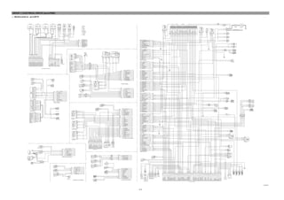
- 21. 4 -20 CN-50 CN-51 36PUMPEPPR(+) 35NC 34RS232(GND) 33RS232(-) 32RS232(+) 31GND 30SERIAL-RX 29SERIAL-TX 28GND(MAIN) 27NC 26NC 25NC BOOMPRIORITYSOL BRAKEFAILLAMP POWERIG BATTERY24V(+) NC PARKINGSW T/MOILLAMP ENGPREHEATER NC COCANCELSOL HOUR-METER ACCELACT(-) ENGOILFILTERSW PRE-HEATSW TRAVELSPEEDSOL OVERLOADSIG 24 NC 23 22 21 20 19 POWERMAXSOL 18 17 16 15 PUMPEPPR(-) 14 TRAVELBUZZER 13 MAXFLOWSOL ACCELACT(+) ANTI-RESTARTRY NC 12 11 10 9 8 7 6 5 4 3 2 1 36NC 35NC 34HYDTEMPSENDOR 33WATERTEMPSENDOR 32PUMPPROLIXSW 31GND(SENSOR) 30NC 29ACCELSW 28T/MOILPS 27BRAKEFAILPS 26TACHOSENSOR(+) 25TACHOSENSOR(-) WORKINGPS FUELLEVELSENSOR POT-SIG TRAVELHi/LoSW ACCELDIALSIG 5V(POT&DIAL) HEAVYLIFTSW GND(POT&DIAL) 24 23 22 21 20 19 TRAVELALARMSW 18 17 16AIRCLEANERSW POWERMAXSW BKT&ARMINPS 3 2 1 6 5 3 1 2 M- M+ NC 6 5 4 M 3 2 1P+ SIG P- AC&HEATER CPU 5 5A 27 12 20A 11 5A 10 5A 9 10A 8 5A 7 10A 6 20A 4 10A 3 5A 2 5A 1 20A CN-46 SPARE SWITCHPANEL CONVERTOR CPU FUELCUT-OFF CLUSTER CASSETTERADIO WIPER AC&HEATER ROOMLAMP STARTKEY 12 11 10 9 ACCEL ACTUATOR CN-76 8 CN-9 7 6 5 4 3 2 1 8 CN-5 7 6 5 4 3 2 1 12 11 10 9 8 CN-1 7 6 5 4 3 2 1 CPU CONTROLLER 2 3 1 6 54 T 1 3 4 6 2 5 1 2 3 4 5 6 CS-7 PROLIX SW rpm 1 2 2 1 CN-75 EPPR V/V CD-17 TACHO SENSOR h 2 1 CN-48 HOUR METER A B C S + CN-142 ACCEL DIAL 2 1 CN-47 RESISTOR - FUSE BOX OR W B B W R B Y OR L OR B W OR V Y OR W B B R L OR WW/OR OR OR OR W B Y L W B Y L W B Y L Y L OR OR OR V B OROR V B CONTROLLER CIRCUIT(up to #1000) 21074EL11
- 22. 4-21 MONITORING CIRCUIT(up to #1000) 21074EL13
- 23. 4-22 1 1 4-19 ELECTRIC CIRCUIT FOR HYDRAURIC CN-50 CN-51 36PUMPEPPR(+) 35NC 34RS232(GND) 33RS232(-) 32RS232(+) 31GND 30SERIAL-RX 29SERIAL-TX 28GND(MAIN) 27NC 26NC 25NC BOOMPRIORITYSOL BRAKEFAILLAMP POWERIG BATTERY24V(+) NC PARKINGSW T/MOILLAMP ENGPREHEATER NC COCANCELSOL HOUR-METER ACCELACT(-) ENGOILFILTERSW PRE-HEATSW TRAVELSPEEDSOL OVERLOADSIG 24 NC 23 22 21 20 19 POWERMAXSOL 18 17 16 15 PUMPEPPR(-) 14 TRAVELBUZZER 13 MAXFLOWSOL ACCELACT(+) ANTI-RESTARTRY NC 12 11 10 9 8 7 6 5 4 3 2 1 36NC 35NC 34HYDTEMPSENDOR 33WATERTEMPSENDOR 32PUMPPROLIXSW 31GND(SENSOR) 30NC 29ACCELSW 28T/MOILPS 27BRAKEFAILPS 26TACHOSENSOR(+) 25TACHOSENSOR(-) WORKINGPS WATERLEVELSW FUELLEVELSENSOR 24V(PRES.SENSOR) POT-SIG TRAVELHi/LoSW O/TDECELSW NC ALTLEVEL BOOMUPPS ENGOILPS ACCELDIALSIG 5V(POT&DIAL) HEAVYLIFTSW TRAVELOILPS GND(POT&DIAL) 24 P1PRESSSIG. 23 22 21 20 19 TRAVELALARMSW 18 17 16 15 GND(PRES.SENSOR) 14 AIRCLEANERSW 13 POWERMAXSW P3PRESSSIG. P2PRESSSIG. BKT&ARMINPS 12 11 10 9 8 7 6 5 4 3 2 1 2 1 Pa 2 1 2 1 Pa 2 1 2 1 2 1 2 1 2 1 2 1Pa 2 1Pa 2 1 2 1 2 1 2 1 2 1C 27 10A 26 10A 25 10A 24 5A 23 10A 22 5A 21 EARTH 1 FUSE BOX CD-37 CD-31 OVERLOAD PS CN-91 1 2 CN-131 BOOM DOWN EPPR BOOM DOWN PRESS GND SIG 24V3 2 1 CD-32 CD-33 BOOM UP PRESS GND SIG 24V3 2 1 6 5 4 3 2 1 CN-14 DO-4 QUICK COUPLING CN-140 CN-13 1 2 CN-66 BREAKER SOL. SAFETY SOL CN-68 CN-81 TRAVEL BZ 2PCSBOOMAUTO-IDLEPS CN-15CN-15 2 1 SPARE FUELFILLERP/P SOLENOID3 SAFETYSOL SOLENOID1 TRAVEL TRAVEL PS CD-6 CD-7 WORK PS CN-133 BOOM PRIORITY1 CN-137 MAX FLOW CN-88 POWER MAX CN-70 TRAVEL CD-1 HYD TEMP 12 11 10 9 8 CN-7 7 6 5 4 3 2 1 12 11 10 9 8 CN-6 7 6 5 4 3 2 1 8 CN-4 7 6 5 4 3 2 1 CN-2 6 5 4 3 2 1 12 11 10 9 8 7 CN-8 6 5 4 3 2 1 CPU CONTROLLER 21 10A 20 10A ETHER(PRE-HEAT) CIGARLIGHTER 7 8 6 2 10 9 8 7 6 5 4 3 2 1 109 5 1 CABIN LIGHT 24V CABIN LIGHT 24V INT. SIG TRAVEL ALARM GND WASHER SIG WORK LIGHT 24V WORK LIGHT 24V HEAD LIHGT 24V CABIN LIGHT OUT CABIN LIGHT OUT POWER 24V PRE-HEAT WIPER MOTOR DRIVE WORK LIGHT OUT WORK LIGHT OUT HEAD LIGHT OUT 17 16 15 14 13 12 11 10 9 8 7 6 5 4 3 2 1 2 1 CN-116 SWITCH PANEL BREAKER SW CS-27 BREAKER CS-26 7 8 6 2 10 9 8 7 6 5 4 3 2 1 109 5 1 I CS-52 BOOM DAMPING SW CS-67 CS-50 QUICKCOUPLINGSWOVERLOADSW 2 1 2 1 SAFETY SW CS-20 A CB C B A POWER MAX CS-19 ONE TOUCH DECEL CS-29 CS-4 SAFETY SW CD-44 PUMP1 PRESS GND SIG 24V 3 2 1 CD-43 CD-42 PUMP2 PRESS PUMP3 PRESS GND SIG 24V 3 2 1 GND SIG 24V 3 2 1 6 5 4 3 2 1 CN-16 20 10AHORN 10 9 8 7 6 5 4 3 2 10 9 8 7 6 5 4 3 2 7 8 6 2 109 5 1 7 8 6 2 109 5 1 R OR R Y GY OR Y L G B GY OR Y L/W G B GY OR Y L/W G Y B B B B LL L G G GY OR OR Y B GY B G OR OR G GY Y G GY Y W L BR G R G V B G GY L V W V BR W R B Y R G GY Y R BR R L R G Y W G Y G R RR VV BB VW VV RR R G W R G W R B V V R B Y B YY B B L B L GY B GY OR GY OR GY OR GY GY GY B G B G B G B W R V BR B W R V BR B W R V B W R V B BR BR B B R R R G W R G W R G W GY B Y B Y Y R B B B B B ELECTRIC CIRCUIT FOR HYDRAULIC(up to #1000) 21074EL12
- 24. 4 -54 1. POWER CIRCUIT (#1001 and up, TIER II) The negative terminal of battery is grounded to the machine chassis through master switch. When the start switch is in the OFF position, the current flows from the positive battery terminal as shown below. OPERATING FLOW Battery Battery relay Fusible link¡†CN-60¡‡ Fuse box¡†No.1¡‡ l/conn¡†CN-8(12)¡‡ Start switch¡†CS-2(1)¡‡ Power relay¡†CR-35(30)] Fuse box¡†No.2¡‡ I/conn¡†CN-10(6)¡‡ Room lamp¡†CL-1(2)¡‡ Door switch¡†CS-1¡‡ Cassette radio¡†CN-27(11)¡‡ Fuse box¡†No.3¡‡ l/conn¡†CN-11(4)¡‡ AC & Heater controller¡†CN -116(3, 4)¡‡ Fuse box¡†No.4¡‡ I/conn¡†CN - 5(4)¡‡ I/conn¡†CN -17(5)¡‡ Wiper motor controller ¡†CN-141(7)¡‡ Wiper motor¡†CN-21(4)¡‡ Fuse box¡†No.5¡‡ CPU controller¡†CN-50(7)¡‡ Fuse box¡†No.6¡‡ I/conn¡†CN-11(5)¡‡ Relay(Hi, M2) ¡ I/conn : Intermediate connector CHECK POINT Engine Start switch Check point Voltage 1) 2) ¡ GND : Ground OFF OFF ¤ - GND (Battery 1EA) ¤Ł- GND (Battery 2EA) ¤Ø- GND (Battery 2EA) ¤Œ - GND (Fusible link) 10~12.5V 20~25V 20~25V 20~25V
- 25. 4-55 POWER CIRCUIT (#1001 and up, TIER II) 21074EL51
- 26. 4 -56 2. STARTING CIRCUIT (#1001 and up, TIER II) OPERATING FLOW Battery(+) terminal Battery relay¡†CR-1¡‡ Reset button¡†CS-61¡‡ Fuse box¡†No.1¡‡ I/conn¡†CN-8(12)¡‡ Start switch¡†CS-2(1)¡‡ When start key switch is in ON position Start switch ON¡†CS-2(2)¡‡ I/conn¡†CN-8(11)¡‡ Battery relay¡†CR-1¡‡ Battery relay operating (All power is supplied with the electric component) Start switch ON¡†CS-2(3)¡‡ I/conn¡†CN-8(10)¡‡ Power relay¡†CR-35(86) ¡ (87)¡‡ Fuse box¡†No.12¡‡ l/conn¡†CN-2(5)¡‡ Fuel cut-off¡†CN-79(1)¡‡ When start key switch is in START position Start switch START¡†CS-2(5)¡‡ I/conn¡†CN-8(9)¡‡ Safety relay¡†CR-5(86) ¡ (30)¡‡ l/conn¡†CN-3(2)¡‡ Start relay¡†CR-23¡‡ l/conn¡†CN-2(4)¡‡ Fuel cut off¡†CN-79(2)¡‡ CHECK POINT 1) (1) (2) 2) Engine Start switch Check point Voltage OPERATING START ¤ - GND(Battery) ¤Ł- GND(Start key) ¤Ø- GND(Battery relay M4) ¤Œ- GND(Starter B+) ¤º- GND(Starter M) ¤ - GND(Start relay) ¤ - GND(Battery relay M8) 20~25V ¡ GND:Ground
- 27. 4-57 STARTING CIRCUIT (#1001 and up, TIER II) 21074EL52
- 28. 4 -58 CHECK POINT 3. CHARGING CIRCUIT (#1001 and up, TIER II) When the starter is activated and the engine is started, the operator releases the key switch to the ON position. Charging current generated by operating alternator flows into the battery through the battery relay (CR-1). The current also flows from alternator to each electrical component and controller through the fuse box. OPERATING FLOW Warning flow Alternator "I" terminal I/conn¡†CN-3(3)¡‡ CPU alternator level¡†CN-51(9)¡‡ Cluster charging warning lamp(Via serial interface) Charging flow Alternator "B+" terminal Battery relay(M8) Battery(+) terminal Reset button¡†CN-60¡‡ Fuse box 1) 2) (1) (2) ¡ GND : Ground Engine Start switch Check point Voltage Run ON ¤ - GND(Battery voltage) ¤Ł- GND(Battery relay) ¤Ø- GND(Alternator B+ terminal) ¤Œ- GND(Alternator I terminal) ¤º- GND(CPU) 20~30V
- 29. 4-59 CHARGING CIRCUIT (#1001 and up, TIER II) 21074EL53
- 30. 4 -60 4. HEAD AND WORK LIGHT CIRCUIT (#1001 and up, TIER II) OPERATING FLOW Fuse box (No.14) I/conn¡†CN-7(7)¡‡ Switch panel¡†CN-116(9)¡‡ Fuse box (No.15) I/conn¡†CN-7(8)¡‡ Switch panel¡†CN-116(10,11)¡‡ Head light switch ON Head light switch ON¡†CN-116(1)¡‡ l/conn¡†CN-7(1)] Head light ON¡†CL-4(2)¡‡: Head lamp ON l/conn¡†CN-10(2)¡‡ Cassette radio illumination ON¡†CN-27(7)¡‡ l/conn¡†CN-11(8)¡‡ AC & Heater controller illumination ON l/conn¡†CN-6(8)¡‡ Cigar light¡†CL-2¡‡ Work light switch ON Work light switch ON¡†CN-116(2,3)¡‡ l/conn¡†CN-7(2)¡‡ l/conn¡†CN-12(1)¡‡ Work light ON¡†CL-5(2), CL-6(2)¡‡ CHECK POINT 1) ¡ GND : Ground (1) (2) 2) Engine Start switch Check point Voltage STOP ON ONSTOP ¤ - GND(Fuse box) ¤Ł- GND(Switch power input) ¤Ø- GND(Switch power output) ¤Œ- GND(Head light) ¤º- GND(Fuse box) ¤ - GND(Switch power input) ¤ -GND(Switch power output) ¤ - GND(Work light) 20~25V 20~25V
- 31. 4-61 HEAD AND WORK LIGHT CIRCUIT (#1001 and up, TIER II) 21074EL54
- 32. 5. BEACON LAMP AND CAB LIGHT CIRCUIT (#1001 and up, TIER II) OPERATING FLOW Fuse box (No.17) I/conn¡†CN-8(3)¡‡ Beacon lamp switch¡†CN-23(6)¡‡ Fuse box (No.16) I/conn¡†CN-7(12)¡‡ Switch panel¡†CN-116(16, 17)¡‡ Beacon lamp switch ON Beacon lamp switch ON¡†CS-23(2)¡‡ Switch lndicator lamp ON¡†CS-23(9)¡‡ l/conn¡†CN-8(4)¡‡ l/conn¡†CN-10(10)¡‡ Beacon lamp ON¡†CL-7¡‡ Cab light switch ON Cab light switch ON¡†CN-116(7, 8)¡‡ I/conn¡†CN-7(6)¡‡ I/conn¡†CN-10(11)¡‡ Cab light ON¡†CL-8(2), CL-9(2)¡‡ CHECK POINT 4 -62 1) 2) (1) (2) ¡ GND : Ground Engine Start switch Check point Voltage STOP STOP ON ON ¤ - GND(Fuse box) ¤Ł- GND(Switch power input) ¤Ø- GND(Switch power output) ¤Œ- GND(Beacon lamp) ¤º- GND(Fuse box) ¤ - GND(Switch power input) ¤ - GND(Switch power output) ¤ - GND(Cab light) 20~25V 20~25V
- 33. 4-63 BEACON LAMP AND CAB LIGHT CIRCUIT (#1001 and up, TIER II) 21074EL55
- 34. 4 -64 6. WIPER AND WASHER CIRCUIT (#1001 and up, TIER II) OPERATING FLOW Key switch ON Fuse box (No.11) I/conn¡†CN-7(5)¡‡ Switch panel¡†CN-116(6)¡‡ Fuse box (No.4) I/conn¡†CN-5(4)¡‡ I/conn¡†CN-17(5)¡‡ Wiper motor controller¡†CN-141(7)¡‡ Wiper motor¡†CN-21(4)¡‡ Fuse box (No.13) I/conn¡†CN-6(5)¡‡ l/conn¡†CN-17(4)¡‡ Wiper motor controller¡†CN-141(6)¡‡ Washer pump¡†CN-22(2)¡‡ Wiper switch ON : 1st step(Intermittent) Wiper switch ON¡†CN-116(15)¡‡ I/conn¡†CN-9(4)¡‡ I/conn¡†CN-6(10)¡‡ I/conn¡†CN-17(8)¡‡ Wiper motor controller¡†CN-141(10) ¡ (3)¡‡ Wiper motor intermittently operating¡†CN-21(6)¡‡ Wiper switch ON : 2nd step(Low speed) Wiper switch ON¡†CN-116(4)¡‡ I/conn¡†CN-7(3)¡‡ I/conn¡†CN-6(9)¡‡ I/conn¡†CN-17(2)¡‡ Wiper motor controller¡†CN-141(2) ¡ (4)¡‡ Wiper motor operating¡†CN-21(2)¡‡ Washer switch ON Washer switch ON¡†CN-116(12)¡‡ I/conn¡†CN-7(9)¡‡ I/conn¡†CN-5(1)¡‡ I/conn¡†CN-17(7)¡‡ Wiper motor controller¡†CN-141(9) ¡ (8)¡‡ I/conn¡†CN-17(6)¡‡ I/conn¡†CN-6(11)¡‡ Washer pump¡†CN-22(1)¡‡ Washer operating Fuse box(No.13) I/conn¡†CN-6(5)¡‡ I/conn¡†CN-17(4)¡‡ Wiper motor controller¡†CN-141(6) ¡ (4)¡‡ Wiper motor operating¡†CN-21(2), Low speed¡‡ Auto parking(When switch OFF) Switch OFF¡†CN-116(15)¡‡ Wiper motor parking position by wiper motor controller CHECK POINT 1) (1) (2) (3) (4) (5) ¡ GND : Ground 2) Engine Start switch Check point Voltage STOP ON ¤ - GND(Fuse box) ¤Ł- GND(Switch power input) ¤Ø- GND(Switch power output) ¤Œ- GND(Wiper Power input) ¤º- GND(Wiper power output) ¤ - GND(Wiper motor) 0 ~ 5V 24V 0 or 24V
- 35. 4-65 WIPER AND WASHER CIRCUIT (#1001 and up, TIER II) 21074EL56
- 36. 4 -66 CONTROLLER CIRCUIT (#1001 and up, TIER II) 21074EL57
- 37. 4-67 MONTORING CIRCUIT (#1001 and up, TIERII) 21074EL58