SlideShare uma empresa Scribd logo
1 de 6
SSPC-PA Guide 11
August 1, 2008
1
SSPC: The Society for Protective Coatings
Paint Application Guide No. 11
Protecting Edges, Crevices, and Irregular Steel Surfaces by Stripe Coating
1. Scope
This guide discusses the technique called “stripe coating”
or “striping” as a way of providing extra corrosion protection
measures on edges, outside corners, crevices, bolt heads,
welds, and other irregular steel surfaces, including optional
surface preparation techniques for sharp edges to improve
coating performance. Some details, including the advantages
and limitations of specific methods of obtaining additional
coating thickness, are described to assist the specification
writer in assuring that the project specification will address
adequate corrosion protection.
2. Background
2.1 Sharp edges, outside corners, crevices, and welds
are often sites where coating failures and corrosion begin due
to reduced coating barrier protection (see Figure 1). Reduced
coating thickness on these surfaces can be a result of applica-
tion of inadequate amounts of coating, but the surface tension
of the wet coating or coating shrinkage during the drying/curing
process can also pull the film away from edges. Sharp edges
resulting from cutting, burning, and shearing are especially
difficult to coat adequately. Bolt threads combine the adverse
effects of sharp edges and crevices.
2.2 The solutions to this problem include (1) eliminating
the irregularities by grinding, mechanical sanding, or filing;
(2) applying a thicker protective coating film to problem areas
such as outside edges, pitted areas, and bolts; (3) applying a
penetrating and/or good wetting coating to crevice areas and/
or inside corners; or a combination of (1) and (2). In some
cases, both grinding and stripe coating may be specified for a
given area. The option of choice is usually determined by the
best cost/benefit ratio. Factors that enter into the cost/benefit
analysisofedgeprotectionincludetheseverityoftheexposure
environment,interferencewithproductionduringmaintenance,
anddifficultyinaccessingthestructuretoperformmaintenance
painting. These factors are unique to each project.
2.4 Sharp edges may be avoided at the prefabrication
stage or remedied by grinding after construction, but at a much
higher cost. When filing edges, care should be taken to assure
that additional sharp edges are not created while modifying the
original edge. It is generally much less expensive and easier
to grind or chamfer edges in the shop than in the field.
2.5 Additional coating thickness can be obtained by
applying an extra layer of coating to the areas requiring addi-
tional protection (the “stripe coat”). In some cases, the “stripe
coat” may be followed by the application of a full coat of a
coating with edge retention properties.
3. Preparing Outside Corners and Sharp
Edges
3.1 Outside corners and sharp edges can be ground such
that the edge is rounded to a 1.6 to 3.2 mm (1/16 to 1/8 inch)
radius. An alternative to rounding is to chamfer the edge to a
specified measurement, so instead of one 90-degree corner,
therearetwo135-degreecorners(seeFigure2).Thewidthofthe
flat ground area, i.e. the distance between the two 135-degree
corners, is usually 1.6 to 3.2 mm (1/16 to 1/8 inch). Paint will
not pull away from a 135-degree corner as much as from a
90-degree corner, resulting in more overall coating thickness.
Further, subsequent abrasive blast cleaning provides some
radius to the 135-degree corners.
Figure 1. Schematic showing how coating thick-
ness is reduced at a sharp edge.
90°
135 °
Chamfer
Figure 2. Chamfering reduces a sharp 90° corner to
two 135° corners.
Poor
Coating
Ideal
SSPC- PA Guide 11
August 1, 2008
2
3.2 The increased performance resulting from rounding
or chamfering edges depends on the service environment, the
generic type of coating and on the radius or size of the chamfer.
One research study1
showed that rounding or chamfering had
no measurable effect if an ethyl silicate inorganic zinc-rich
(IOZ) coating was applied over blast cleaned steel. Therefore,
there is no need to go to the added expense of grinding edges
if ethyl silicate IOZ coating is specified. However, the same
study indicated that rounding or chamfering edges before
application of an alkyd or organic zinc-rich primer improved
the coating’s performance. Even with edge rounding or cham-
fering, it is necessary that proper spray application techniques
be used.2,3
The use of coatings with edge-retention properties
(see Section 4.7.3) may also minimize or eliminate the need
for edge grinding.
3.3 Edge grinding is best done in the shop before blast
cleaning where the work is accessible. A sample statement
in a specification may read, “All corners and edges shall be
rounded to a 2 mm radius (1/16 inch) or ground to a 2 mm
(1/16 inch) chamfer.” In addition to edges, rough surfaces are
ground smooth. Flame cut edges are normally ground over
their entire surface to remove the hardened surface layer
resulting from flame cutting and permit creation of a profile.
For immersion service and other services where increased
corrosion can be expected, very rough welds should always
be ground because many coatings cannot adequately protect
them. NACE Standard RP0178 "Standard Recommended
Practice: Fabrication Details, Surface Finish Requirements,
and Proper Design Considerations for Tanks and Vessels to
Be Lined for Immersion Service"4
provides guidance on finish
requirements for welds.
4. Stripe Coat Application
A “stripe coat” is a coat of paint applied only to edges,
welds, outside corners, bolt heads and threads, and crevices,
either before or after a full coat is applied to the entire surface.
These areas are difficult to coat due to coating shrinkage
during cure. Shrinkage pulls coating away from sharp edges,
resulting in low dry film thickness. Wet coating may flow over
rather than into crevices. This results in a temporary creating
bridge over the crevice that disappears as the coating cures
and shrinks, leaving the crevice interior unprotected. Both
areas are susceptible to premature corrosion. The practice
of applying a “stripe coat” to such areas is frequently referred
to as “striping.”
The project specification normally specifies the areas are
to be striped, how to apply the stripe coat (brush or spray), in
what order to apply the stripe coat (before or after the full coat),
which coats are to be striped, whether tinting of the stripe coat
or use of another color of coating is required, and information
on the drying/curing requirements between application of the
stripe and full coat (may defer to the coating manufacturer).
4.1AreastoStripe:Thefacilityownernormallydetermines
whether stripe coating is warranted for some or all areas of the
particular project. Sometimes only specified areas of outside
corners, edges, welds, and crevices are striped. Situations
where stripe coating is usually warranted are:
Immersion service (e.g., interiors of fuel or water•	
storage tanks; ship hulls)
Areas with high corrosion rates (e.g. cooling towers•	
and splash zones)
Areas where access is difficult (e.g., towers, some•	
bridges).
Built up members (e.g., lattice bars and boxes)•	
Situations where stripe coating may not be cost effective
are:
Non-critical components (e.g., interior wall in living•	
space on a ship)
Mild exposure (e.g., SSPC environmental exposure•	
zones 1A and 1B(1),5
Inside corners (can be adequately covered using•	
proper spray technique)
Areas that are usually stripe coated include:
Crevices•	
Plate and sharp edges•	
Plate seams•	
Back-to-back angle seams (built up members)•	
Pitted steel•	
Bolt heads and nuts•	
Rivet heads•	
Welds•	
Other sharp discontinuities•	
Outside corners•	
•	
Stripe coating is most effective on edges that are either
rounded or chamfered by grinding (see Section 3).
4.2 How to Stripe
4.2.1 Brushing is the preferred method of applying stripe
coats. Unless otherwise specified, SSPC-PA 1 requires brush
application of coatings to cracks, crevices, blind areas of all
rivets and bolts, and all areas of limited access.(2),6
Brush
application provides the highest quality stripe coat on most
surfaces because it works the paint into the pores and crevices
and allows the greatest control over the boundaries of the
painted area. The coating should be allowed to dry to recoat
according to the product data sheet before the full prime coat
is applied. Coating manufacturers will usually provide guid-
ance on the amount of dry time required before application of
(1)
	SSPC Environmental Zone 1A–Interior, normally dry (or tem-
porary protection). Very mild (oil base paints now last six years
or more). SSPC Environmental Zone 1B–Exterior, normally dry
(includes most areas where oil base paints now last six years or
more)4
(2)
	SSPC-PA 1, Section 7.4.6.
SSPC-PA Guide 11
August 1, 2008
3
subsequent coatings. Table 1 compares application of stripe
coats by brush or spray.
4.2.2Whenapplyingastripecoat,thebrushstrokesshould
run parallel to, not across, edges and crevices. Variations in
pressure of the brush during application can result in thin film
on sharp edges and accumulation of coating on adjoining
perpendicularsurfaces.Toassureadequatefilmbuildonsharp
edges, multiple brush applications may be necessary. Bolt
heads and nuts should be striped in a circular brush motion.
Striping should extend at least 3 centimeters (cm) (1 inch) from
edges and other irregular surfaces. Round or oval brushes are
generally considered most suitable for rivets, bolts, irregular
surfaces, and rough or pitted steel.
4.2.3 SSPC-PA 1 does not permit rollers to be used to
applycoatingsonirregularsurfaces,suchasrivets,boltheads,
crevices, welds, corners or edges unless otherwise specified.
(3)
If the project specification permits the use of rollers for stripe
coat application in these areas, PA 1 requires that the coating
be brushed out to form a continuous and unbroken film over
these surfaces.
4.2.4 Spraying the stripe coat can reduce the amount
of time spent in brush application, but the painter has less
control over the precise boundaries of the area being coated.
Spray may be the best method for applying stripe coats using
coatings with edge retention properties or zinc-rich coatings,
or for applying a stripe coat to edges that have already been
painted. The applicator should spray the coating along the flat
surface, not directly at the edge itself, to prevent the atomiza-
tion pressure from pushing the coating away from the edge
that is to be protected.
3	 SSPC-PA 1, Section 7.3.4.
4.2.5 When striping with a coating that is prone to pigment
settling, such as zinc-rich primers, the coating in the pot should
be constantly agitated, unless otherwise recommended by the
coating manufacturer.
4.2.6Whenstripingwithamulti-componentthermosetting
coating, the curing reaction will eventually progress to the point
where the coating fails to wet the surface and level adequately.
Sincehightemperaturesoftenacceleratecuringrates,thiseffect
ismostpronouncedinhotweather.Heatofreaction(exotherm)
may also be generated when multiple components of thermo-
setting coatings are mixed, so it may be more cost effective
to use smaller kits (e.g., 1-liter or 1-gallon units) rather than
5-liter or 5-gallon units. Note that most coating manufacturers
prohibit mixing of partial kits. Thinning should not be used to
restore the flow properties of a multi-component coating that
has increased viscosity from partial curing.
4.2.7 It is good practice for the stripe coat to be a different
color from the adjoining full coats or the bare steel surface.
Thecolordifferenceenablespaintersandinspectorstovisually
verify there are no misses, skips, or thin spots in the stripe coat.
In addition, the application can be verified after the fact (as
necessary) for thickness and proper coverage using a destruc-
tive thickness gage (i.e., Tooke Gage), a holiday detector, or
(on some specialty coatings) ultraviolet light.
4.3 What Coats to Stripe: Usually, a stripe application is
specified for the primer coating because of the importance of
complete coverage. After a surface has received its first coat
of paint, there is less probability of incomplete coverage of
subsequent coats. Occasionally, multiple stripe coats may be
required over rough hand welds. In critical areas, the specifier
TABLE 1
COMPARISON OF APPLICATION METHODS
APPLICATION
METHOD
ADVANTAGES DISADVANTAGES
Brush Best method to work paint into pores and•	
crevices
Most complete coverage of rivet heads, bolt•	
heads, nuts, and threads
Best control of extent of area coated•	
Most labor-intensive method•	
May pull incompletely cured paint from edge•	
Spray Fastest method of application•	
Least labor-intensive method•	
May be best method of applying coatings with•	
edge retention properties, zinc-rich coatings
Quick method for applying a stripe coat to•	
edges al-ready painted
May bridge (rather than penetrate into) pores and crev-•	
ices. Back-brushing needed to work wet coating into
pits, crevices, and angles.
More likely to miss areas in tight spaces, resulting in•	
holidays.
Builds coating thickness on larger area (control of area•	
coated is difficult)
More risk of overspray and dry spray•
SSPC- PA Guide 11
August 1, 2008
4
may require that striping be done for two or more coats in a
multi-coat system. Nevertheless, multiple coat striping is not
commonly specified.
4.4 When to Stripe - Before or After Full Coat
4.4.1 Many coatings professionals feel that the stripe
coat of the primer should be applied first to maximize corro-
sion protection. For example, it is easier to work stripe coats
into crevices that have not been bridged by a spray-applied
full coat. However, there are several reasons why the stripe
coat could be applied after the first full coat. If the stripe coat
is applied prior to primer application, there is opportunity for
the surrounding clean, unprotected steel to deteriorate while
the stripe coat is drying/curing. Another reason is that stripe
coating after application of the full coat (particularly an inter-
mediate coat) will fill in pinholes and other holidays that have
formed in the spray-applied coat.
4.4.2 If striping is specified for each coat in a multi-coat
system, application of the stripe coat before the final finish
coat will result in a more uniform finish.
4.4.3 When painting a tank floor or other surface subject
to foot or vehicle traffic, it may be wise to delay application of
the final stripe coat over the welds to minimize erosion of the
coating by foot traffic or air hoses being dragged across the
raised welds prior to the coating being put into service.
4.4.4 The advantages and limitations of striping before
and after the full coat are summarized in Table 2. Final deter-
mination of the best sequence of stripe coats and full coats will
depend on the coating systems being used and the specific
requirements of each project.
4.5 If the stripe coat is applied first, it is usually allowed to
dry to touch (per ASTM D 1640) before the full coat is applied.
However,therecanbeexceptionstothispractice.Therecoating
instructions in the coating manufacturer’s product data sheet
should be followed unless otherwise specified.
4.6 Controlling Thickness
4.6.1 The thickness of the stripe coat is difficult to control.
Somecontractorswillmeasurethicknesstoassuretheminimum
and maximum specified thickness limits have been satisfied,
while others will make only a visual check for excessive build.
For the most part, thickness is controlled by the skill of the
applicatoranduseofawetfilmthickness(WFT)gage.However,
notch gages cannot provide reliable WFTreadings on irregular
surfaces and should not be used on edges.
4.6.2 Leeway on maximum thickness is usually allowed
within 2 inches (5 cm) of an edge or 1 inch (3 cm) of a weld.
Coatings may be tolerant of thickness beyond the specified
upper limit. Near a striped area (2 inches [5 cm] from an edge
and 1 inch [3 cm] from a weld), the maximum thickness is
sometimesallowedtobetwicethenormalmaximum.Designers
orspecifiersshouldusecoatingmanufacturer’srecommended
dry film thickness (DFT) ranges as guidance for required thick-
ness of a stripe coat.
4.6.3Conflictscanbeavoidedifthicknessrequirementsat
or near the stripe coat and any allowed deviation from speci-
fied minimum and maximum DFT thickness requirements are
clearly stated in the project specification.
4.6.4 Although thickness of the stripe coat can often be
measured in the immediate vicinity of an edge, it is very difficult
to measure thickness of a coating over the edge itself. Some
TABLE 2
ADVANTAGES AND LIMITATIONS OF STRIPING
BEFORE VS. AFTER APPLICATION OF FULL COAT
TIMING ADVANTAGES LIMITATIONS
BEFORE Better application and protection of irregularities•	
Better appearance•	
Holidays, light spots are more obvious•	
Assists painter in monitoring progress•	
Rust-back of cleaned areas surrounding•	
the striped area may occur before full coat
can be applied
AFTER Surroundingblastcleanedsurfacewillnotrustwhile•	
stripe coat dries
Can sometimes apply by spray (brush-back usually•	
required)
Better coverage of pinholes and holidays•	
Can visually ensure that stripe coat has been•	
applied properly
Damage to previously coated surfaces•	
may occur during application of stripe
coat
Higher chance of incomplete coverage of•	
irregularities
Aesthetics (stripe coat may be more•	
visible)
SSPC-PA Guide 11
August 1, 2008
5
electronic gages include very small tips (probes) to improve
the reliability of dry film thickness readings taken on an edge.
Notches in the probe tip aid in alignment of the gauge and thin
flexible shims can be used to verify the accuracy of the gauge
when measuring on an edge.
4.7 Coatings to Use for Striping
4.7.1 Welds and crevices are best protected when striped
with a coating with good wetting properties. High build coat-
ings are best for striping edges. However, it is impractical
to specify two different stripe coatings on a job with edges,
crevices and welds. The paint should be of a consistency to
function on both surfaces.
4.7.2 The manufacturer should be consulted to determine
the appropriate coating to use for the striping. If the stripe coat
contains a zinc loading and is to be applied over a surface
already primed with inorganic zinc, an organic zinc primer
is used for the stripe coat, as inorganic zinc coatings do not
bond well over themselves or over organic zinc. High solids
coatings may have a relatively short dry time and may not
possess good wetting properties, which is paramount to the
success of the stripe coat. In this case, a compatible stripe coat
with a slower drying time and improved wetting may be used
with the high-solids coating. The coating selected for striping
should be designed for the service environment.
4.7.3 Coatings with Edge Retention Properties: An
alternative method for the protection of edges that may avoid
the need for grinding and chamfering is the use of a coating
that has edge retention properties. Typically these types of
coatings are high-solids products that provide improved film
thicknessretentionattheapexofanedgetoimproveprotection
inthesecriticalareas.Amethodformeasuringtheedgeretention
properties of a coating is published in MIL-PRF-23236C.7
This
test method compares the film thickness of three specimens
cut from a sample of coating applied to a non-chamfered 90
degree angle. The ratio of the film thickness at the apex vs. the
film thickness on the flat area is calculated and expressed as
the percentage of edge retention of the coating, as shown in
Figure3.AccordingtoMIL-PRF-23236C,anyspecimenhaving
less than 50 percent edge retention fails the test. An average
value of 70 percent edge retention for three test specimens
measured using an optical microscope is required to qualify
a coating as having edge-retention properties.
Note that very sharp edges, or “knife” edges, are very
difficult to protect even with coatings with edge-retention
properties. It is recommended that “knife” edges have their
surface modified as described in Section 3 prior to coating to
provide suitable corrosion protection.
5. Disclaimer
5.1 This guide is designed to describe, review, or analyze
new or improved technology and does not meet the definition
of a standard as defined by SSPC. A guide differs from a stan-
dard in that it is not suitable for referencing in a specification or
procurement document. SSPC guides are intended to provide
consensus recommendations for best industry practice. They
are not written as requirements that may be cited in a contract.
However,specifiersmayincorporateinformationfromanSSPC
guide into job-specific contract requirements.
5.2 While every precaution is taken to ensure that all
informationfurnishedinSSPCguidesisasaccurate,complete,
and useful as possible, SSPC cannot assume responsibility
nor incur any obligation resulting from the use of any materials,
coatings, or methods described herein, or of the guide itself.
5.3 This guide does not attempt to address problems
concerning safety associated with its use. The user of this
specification, as well as the user of all products or practices
described herein, is responsible for instituting appropriate
health and safety practices and for ensuring compliance with
all governmental regulations.
References
1. Corbett, W. D. “The Same Old Grind...An Investigation
ofZinc-RichPrimerPerformanceOverSteelCorners.”Modern
Steel Construction, Vol. 40, No. 6: p. 43-49.
2. Graco Publications, Airless Spray Techniques. Minne-
apolis, MN: Graco Inc., 1993. This document is available as a
downloadable .pdf file from http://www.graco.com.
3.GracoPublications,AirSprayTechniques.Minneapolis,
MN: Graco Inc., 1995. This document is available as a down-
loadable .pdf file from http://www.graco.com.
4. NACE Standard RP0178 (latest edition); Standard
Recommended Practice: Fabrication Details, Surface Finish
Requirements, and Proper Design Considerations for Tanks
and Vessels to Be Lined for Immersion Service.”
Measure paint thickness
here (dft )
Measure paint thickness here (dft )
PAIN
T
PAIN
T
SU
BSTR
ATE
flat
Measure paint thickness
here (dft )flat
edge
Figure 3. Diagram of edge retention test
(courtesy of MIL-PRF-23236C)
The edge retention percentage is calculated as:
% Retention = dft (edge)/dft (flat) x 100
SSPC- PA Guide 11
August 1, 2008
6
5. SSPC, “How to Use SSPC Standards and Guides.”
Pittsburgh,PA:SSPC,2008.Houston,TX:NACEInternational.
This standard is available from NACE International at http://
www.nace.org.
6. SSPC-PA 1 (latest edition), Shop, Field, and Mainte-
nance Painting of Steel. Pittsburgh, PA: SSPC.This standard
is available online at http:// www.sspc.org.
7. MIL-PRF-23236C (latest edition); Coating System for
ShipStructures.WashingtonNavyYard,DC:NavalSeaSystems
Command. This standard is available online at http://assist.
daps.dla.mil/quicksearch

Mais conteúdo relacionado

Mais procurados

Stainless steels, problems causes-remedies
Stainless steels, problems causes-remediesStainless steels, problems causes-remedies
Stainless steels, problems causes-remediesAnnamalai Ram
 
Painting procedure rev 0 (d 1157)
Painting procedure rev 0 (d 1157)Painting procedure rev 0 (d 1157)
Painting procedure rev 0 (d 1157)ghani386
 
Procedure qualification
Procedure qualificationProcedure qualification
Procedure qualificationvaasuBandaru
 
Surface Preparation & Treatment
Surface Preparation & TreatmentSurface Preparation & Treatment
Surface Preparation & TreatmentAnsar Lawi
 
WELDING JOINT DESING AND WELDINGSYMBOLS
WELDING JOINT DESING AND WELDINGSYMBOLSWELDING JOINT DESING AND WELDINGSYMBOLS
WELDING JOINT DESING AND WELDINGSYMBOLSRAJA K
 
How to review wps part 1 (mau company)
How to review wps part 1 (mau company)How to review wps part 1 (mau company)
How to review wps part 1 (mau company)Mohamed Farouk
 
Companion Guide to the Asme Boiler & Pressure Vessel Codes. Vol. 1_ Criteria...
Companion Guide to the Asme Boiler & Pressure Vessel Codes.  Vol. 1_ Criteria...Companion Guide to the Asme Boiler & Pressure Vessel Codes.  Vol. 1_ Criteria...
Companion Guide to the Asme Boiler & Pressure Vessel Codes. Vol. 1_ Criteria...sayujkaruvathil1
 
Asme sec ix overview
Asme sec ix overviewAsme sec ix overview
Asme sec ix overviewAshifuddinAli
 
Welding Joint Design and Welding Symbols.pptx
Welding Joint Design and Welding Symbols.pptxWelding Joint Design and Welding Symbols.pptx
Welding Joint Design and Welding Symbols.pptxShah Nadzri Jasmir
 
Painting and coating for industrial
Painting and coating for industrialPainting and coating for industrial
Painting and coating for industrialHASAN OZDEMIR
 
Welding distortion and its control
Welding distortion and its controlWelding distortion and its control
Welding distortion and its controlAnnamalai Ram
 

Mais procurados (20)

2 Construction
2 Construction2 Construction
2 Construction
 
Stainless steels, problems causes-remedies
Stainless steels, problems causes-remediesStainless steels, problems causes-remedies
Stainless steels, problems causes-remedies
 
Post weld heat treatment 06
Post weld heat treatment 06Post weld heat treatment 06
Post weld heat treatment 06
 
Qc piping guide
Qc piping guideQc piping guide
Qc piping guide
 
Painting procedure rev 0 (d 1157)
Painting procedure rev 0 (d 1157)Painting procedure rev 0 (d 1157)
Painting procedure rev 0 (d 1157)
 
Procedure qualification
Procedure qualificationProcedure qualification
Procedure qualification
 
Surface Preparation & Treatment
Surface Preparation & TreatmentSurface Preparation & Treatment
Surface Preparation & Treatment
 
Heat Treatment
Heat TreatmentHeat Treatment
Heat Treatment
 
WELDING JOINT DESING AND WELDINGSYMBOLS
WELDING JOINT DESING AND WELDINGSYMBOLSWELDING JOINT DESING AND WELDINGSYMBOLS
WELDING JOINT DESING AND WELDINGSYMBOLS
 
236135365 heat-treatment-manual
236135365 heat-treatment-manual236135365 heat-treatment-manual
236135365 heat-treatment-manual
 
How to review wps part 1 (mau company)
How to review wps part 1 (mau company)How to review wps part 1 (mau company)
How to review wps part 1 (mau company)
 
Companion Guide to the Asme Boiler & Pressure Vessel Codes. Vol. 1_ Criteria...
Companion Guide to the Asme Boiler & Pressure Vessel Codes.  Vol. 1_ Criteria...Companion Guide to the Asme Boiler & Pressure Vessel Codes.  Vol. 1_ Criteria...
Companion Guide to the Asme Boiler & Pressure Vessel Codes. Vol. 1_ Criteria...
 
Welding Defects
Welding DefectsWelding Defects
Welding Defects
 
Welding defects
Welding defectsWelding defects
Welding defects
 
Asme sec ix overview
Asme sec ix overviewAsme sec ix overview
Asme sec ix overview
 
Welding Joint Design and Welding Symbols.pptx
Welding Joint Design and Welding Symbols.pptxWelding Joint Design and Welding Symbols.pptx
Welding Joint Design and Welding Symbols.pptx
 
Shell fabrication.pptx
Shell fabrication.pptxShell fabrication.pptx
Shell fabrication.pptx
 
Lethal service quick guide
Lethal service   quick guideLethal service   quick guide
Lethal service quick guide
 
Painting and coating for industrial
Painting and coating for industrialPainting and coating for industrial
Painting and coating for industrial
 
Welding distortion and its control
Welding distortion and its controlWelding distortion and its control
Welding distortion and its control
 

Destaque

Implementación de nuevas tecnologías en marketing
Implementación de nuevas tecnologías en marketingImplementación de nuevas tecnologías en marketing
Implementación de nuevas tecnologías en marketingGalaxy PRO
 
Online Course Catalog 2009
Online Course Catalog 2009Online Course Catalog 2009
Online Course Catalog 2009Allied Schools
 
Ensayo de ordinario de taller de radio
Ensayo de ordinario de taller de radioEnsayo de ordinario de taller de radio
Ensayo de ordinario de taller de radioGalaxy PRO
 
CURRICULAM-VITAE
CURRICULAM-VITAECURRICULAM-VITAE
CURRICULAM-VITAENasim Khan
 
Yaw Owusu Resume-2
Yaw Owusu Resume-2Yaw Owusu Resume-2
Yaw Owusu Resume-2Yaw Owusu
 
WINSTON S KILBURN Resume 1
WINSTON S KILBURN Resume 1WINSTON S KILBURN Resume 1
WINSTON S KILBURN Resume 1Winston Kilburn
 
Adam Wiltse Resume
Adam Wiltse ResumeAdam Wiltse Resume
Adam Wiltse ResumeAdam Wiltse
 
Executive Profile in Teletime, Brazil's major telecom magazine
Executive Profile in Teletime, Brazil's major telecom magazineExecutive Profile in Teletime, Brazil's major telecom magazine
Executive Profile in Teletime, Brazil's major telecom magazineEduardo Miccolis
 
Presentacion 16 17
Presentacion 16 17Presentacion 16 17
Presentacion 16 17Adc Ensanche
 
Explosion reynosa pemex
Explosion reynosa pemexExplosion reynosa pemex
Explosion reynosa pemexGalaxy PRO
 

Destaque (16)

Implementación de nuevas tecnologías en marketing
Implementación de nuevas tecnologías en marketingImplementación de nuevas tecnologías en marketing
Implementación de nuevas tecnologías en marketing
 
Online Course Catalog 2009
Online Course Catalog 2009Online Course Catalog 2009
Online Course Catalog 2009
 
Ensayo de ordinario de taller de radio
Ensayo de ordinario de taller de radioEnsayo de ordinario de taller de radio
Ensayo de ordinario de taller de radio
 
CURRICULAM-VITAE
CURRICULAM-VITAECURRICULAM-VITAE
CURRICULAM-VITAE
 
Artist Resume
Artist ResumeArtist Resume
Artist Resume
 
Yaw Owusu Resume-2
Yaw Owusu Resume-2Yaw Owusu Resume-2
Yaw Owusu Resume-2
 
Programa fisica cei
Programa fisica ceiPrograma fisica cei
Programa fisica cei
 
WINSTON S KILBURN Resume 1
WINSTON S KILBURN Resume 1WINSTON S KILBURN Resume 1
WINSTON S KILBURN Resume 1
 
Resume.AM
Resume.AMResume.AM
Resume.AM
 
Adam Wiltse Resume
Adam Wiltse ResumeAdam Wiltse Resume
Adam Wiltse Resume
 
LOR_MichalSzuba
LOR_MichalSzubaLOR_MichalSzuba
LOR_MichalSzuba
 
Executive Profile in Teletime, Brazil's major telecom magazine
Executive Profile in Teletime, Brazil's major telecom magazineExecutive Profile in Teletime, Brazil's major telecom magazine
Executive Profile in Teletime, Brazil's major telecom magazine
 
P3 lno41014b
P3 lno41014bP3 lno41014b
P3 lno41014b
 
Proyecto final
Proyecto finalProyecto final
Proyecto final
 
Presentacion 16 17
Presentacion 16 17Presentacion 16 17
Presentacion 16 17
 
Explosion reynosa pemex
Explosion reynosa pemexExplosion reynosa pemex
Explosion reynosa pemex
 

Semelhante a Stripe coat

Coating work in the fabrication shop
Coating work in the fabrication shopCoating work in the fabrication shop
Coating work in the fabrication shopTanmay Gor
 
Good-painting-practic-amp-maintenance-amp-repair-painting-standard.pdf
Good-painting-practic-amp-maintenance-amp-repair-painting-standard.pdfGood-painting-practic-amp-maintenance-amp-repair-painting-standard.pdf
Good-painting-practic-amp-maintenance-amp-repair-painting-standard.pdfNguyenQuang243252
 
Electroplating - Spencer Electroplating
Electroplating - Spencer ElectroplatingElectroplating - Spencer Electroplating
Electroplating - Spencer Electroplatingspencerelectroplating
 
Induron coatings t&d
Induron coatings t&dInduron coatings t&d
Induron coatings t&dKendall Smith
 
Pre treatment of Surface coatings.pdf
Pre treatment of Surface coatings.pdfPre treatment of Surface coatings.pdf
Pre treatment of Surface coatings.pdfSanDeepSharma926061
 
Study of sliding wear rate of hot rolled steel specimen subjected to Zirconia...
Study of sliding wear rate of hot rolled steel specimen subjected to Zirconia...Study of sliding wear rate of hot rolled steel specimen subjected to Zirconia...
Study of sliding wear rate of hot rolled steel specimen subjected to Zirconia...IJERA Editor
 
Nano coating solder
Nano coating solderNano coating solder
Nano coating solderFCT Solder
 
6000 Series aluminum Extrusion processs-2023.pptx
6000 Series aluminum Extrusion processs-2023.pptx6000 Series aluminum Extrusion processs-2023.pptx
6000 Series aluminum Extrusion processs-2023.pptxsrinivasrao394717
 
DLC coatings in oil and gas production
DLC coatings in oil and gas productionDLC coatings in oil and gas production
DLC coatings in oil and gas productionTomasz Liskiewicz
 
Conformal coating masking technical bulletin
Conformal coating masking technical bulletinConformal coating masking technical bulletin
Conformal coating masking technical bulletinLee Hitchens
 
Surface condition impacts part performancwe
Surface condition impacts part performancweSurface condition impacts part performancwe
Surface condition impacts part performancweDave Davidson
 
Surface condition impacts part performancwe
Surface condition impacts part performancweSurface condition impacts part performancwe
Surface condition impacts part performancweDave Davidson
 

Semelhante a Stripe coat (20)

Coating work in the fabrication shop
Coating work in the fabrication shopCoating work in the fabrication shop
Coating work in the fabrication shop
 
Introduction to linings
Introduction to liningsIntroduction to linings
Introduction to linings
 
Good-painting-practic-amp-maintenance-amp-repair-painting-standard.pdf
Good-painting-practic-amp-maintenance-amp-repair-painting-standard.pdfGood-painting-practic-amp-maintenance-amp-repair-painting-standard.pdf
Good-painting-practic-amp-maintenance-amp-repair-painting-standard.pdf
 
Electroplating - Spencer Electroplating
Electroplating - Spencer ElectroplatingElectroplating - Spencer Electroplating
Electroplating - Spencer Electroplating
 
2395 1
2395 12395 1
2395 1
 
Spencer Electroplating Service
Spencer Electroplating ServiceSpencer Electroplating Service
Spencer Electroplating Service
 
Induron coatings t&d
Induron coatings t&dInduron coatings t&d
Induron coatings t&d
 
Pre treatment of Surface coatings.pdf
Pre treatment of Surface coatings.pdfPre treatment of Surface coatings.pdf
Pre treatment of Surface coatings.pdf
 
04099
0409904099
04099
 
Study of sliding wear rate of hot rolled steel specimen subjected to Zirconia...
Study of sliding wear rate of hot rolled steel specimen subjected to Zirconia...Study of sliding wear rate of hot rolled steel specimen subjected to Zirconia...
Study of sliding wear rate of hot rolled steel specimen subjected to Zirconia...
 
Nano coating solder
Nano coating solderNano coating solder
Nano coating solder
 
Casing design
Casing designCasing design
Casing design
 
Juan 2015
Juan 2015Juan 2015
Juan 2015
 
6000 Series aluminum Extrusion processs-2023.pptx
6000 Series aluminum Extrusion processs-2023.pptx6000 Series aluminum Extrusion processs-2023.pptx
6000 Series aluminum Extrusion processs-2023.pptx
 
SPE 134239
SPE 134239SPE 134239
SPE 134239
 
DLC coatings in oil and gas production
DLC coatings in oil and gas productionDLC coatings in oil and gas production
DLC coatings in oil and gas production
 
Conformal coating masking technical bulletin
Conformal coating masking technical bulletinConformal coating masking technical bulletin
Conformal coating masking technical bulletin
 
Surface condition impacts part performancwe
Surface condition impacts part performancweSurface condition impacts part performancwe
Surface condition impacts part performancwe
 
Surface condition impacts part performancwe
Surface condition impacts part performancweSurface condition impacts part performancwe
Surface condition impacts part performancwe
 
3.doc
3.doc3.doc
3.doc
 

Último

"Exploring the Essential Functions and Design Considerations of Spillways in ...
"Exploring the Essential Functions and Design Considerations of Spillways in ..."Exploring the Essential Functions and Design Considerations of Spillways in ...
"Exploring the Essential Functions and Design Considerations of Spillways in ...Erbil Polytechnic University
 
Comprehensive energy systems.pdf Comprehensive energy systems.pdf
Comprehensive energy systems.pdf Comprehensive energy systems.pdfComprehensive energy systems.pdf Comprehensive energy systems.pdf
Comprehensive energy systems.pdf Comprehensive energy systems.pdfalene1
 
Mine Environment II Lab_MI10448MI__________.pptx
Mine Environment II Lab_MI10448MI__________.pptxMine Environment II Lab_MI10448MI__________.pptx
Mine Environment II Lab_MI10448MI__________.pptxRomil Mishra
 
Robotics Group 10 (Control Schemes) cse.pdf
Robotics Group 10  (Control Schemes) cse.pdfRobotics Group 10  (Control Schemes) cse.pdf
Robotics Group 10 (Control Schemes) cse.pdfsahilsajad201
 
Computer Graphics Introduction, Open GL, Line and Circle drawing algorithm
Computer Graphics Introduction, Open GL, Line and Circle drawing algorithmComputer Graphics Introduction, Open GL, Line and Circle drawing algorithm
Computer Graphics Introduction, Open GL, Line and Circle drawing algorithmDeepika Walanjkar
 
ROBOETHICS-CCS345 ETHICS AND ARTIFICIAL INTELLIGENCE.ppt
ROBOETHICS-CCS345 ETHICS AND ARTIFICIAL INTELLIGENCE.pptROBOETHICS-CCS345 ETHICS AND ARTIFICIAL INTELLIGENCE.ppt
ROBOETHICS-CCS345 ETHICS AND ARTIFICIAL INTELLIGENCE.pptJohnWilliam111370
 
US Department of Education FAFSA Week of Action
US Department of Education FAFSA Week of ActionUS Department of Education FAFSA Week of Action
US Department of Education FAFSA Week of ActionMebane Rash
 
System Simulation and Modelling with types and Event Scheduling
System Simulation and Modelling with types and Event SchedulingSystem Simulation and Modelling with types and Event Scheduling
System Simulation and Modelling with types and Event SchedulingBootNeck1
 
Prach: A Feature-Rich Platform Empowering the Autism Community
Prach: A Feature-Rich Platform Empowering the Autism CommunityPrach: A Feature-Rich Platform Empowering the Autism Community
Prach: A Feature-Rich Platform Empowering the Autism Communityprachaibot
 
Robotics-Asimov's Laws, Mechanical Subsystems, Robot Kinematics, Robot Dynami...
Robotics-Asimov's Laws, Mechanical Subsystems, Robot Kinematics, Robot Dynami...Robotics-Asimov's Laws, Mechanical Subsystems, Robot Kinematics, Robot Dynami...
Robotics-Asimov's Laws, Mechanical Subsystems, Robot Kinematics, Robot Dynami...Sumanth A
 
Katarzyna Lipka-Sidor - BIM School Course
Katarzyna Lipka-Sidor - BIM School CourseKatarzyna Lipka-Sidor - BIM School Course
Katarzyna Lipka-Sidor - BIM School Coursebim.edu.pl
 
Levelling - Rise and fall - Height of instrument method
Levelling - Rise and fall - Height of instrument methodLevelling - Rise and fall - Height of instrument method
Levelling - Rise and fall - Height of instrument methodManicka Mamallan Andavar
 
Energy Awareness training ppt for manufacturing process.pptx
Energy Awareness training ppt for manufacturing process.pptxEnergy Awareness training ppt for manufacturing process.pptx
Energy Awareness training ppt for manufacturing process.pptxsiddharthjain2303
 
Artificial Intelligence in Power System overview
Artificial Intelligence in Power System overviewArtificial Intelligence in Power System overview
Artificial Intelligence in Power System overviewsandhya757531
 
THE SENDAI FRAMEWORK FOR DISASTER RISK REDUCTION
THE SENDAI FRAMEWORK FOR DISASTER RISK REDUCTIONTHE SENDAI FRAMEWORK FOR DISASTER RISK REDUCTION
THE SENDAI FRAMEWORK FOR DISASTER RISK REDUCTIONjhunlian
 
SOFTWARE ESTIMATION COCOMO AND FP CALCULATION
SOFTWARE ESTIMATION COCOMO AND FP CALCULATIONSOFTWARE ESTIMATION COCOMO AND FP CALCULATION
SOFTWARE ESTIMATION COCOMO AND FP CALCULATIONSneha Padhiar
 
Turn leadership mistakes into a better future.pptx
Turn leadership mistakes into a better future.pptxTurn leadership mistakes into a better future.pptx
Turn leadership mistakes into a better future.pptxStephen Sitton
 
11. Properties of Liquid Fuels in Energy Engineering.pdf
11. Properties of Liquid Fuels in Energy Engineering.pdf11. Properties of Liquid Fuels in Energy Engineering.pdf
11. Properties of Liquid Fuels in Energy Engineering.pdfHafizMudaserAhmad
 
Novel 3D-Printed Soft Linear and Bending Actuators
Novel 3D-Printed Soft Linear and Bending ActuatorsNovel 3D-Printed Soft Linear and Bending Actuators
Novel 3D-Printed Soft Linear and Bending ActuatorsResearcher Researcher
 

Último (20)

"Exploring the Essential Functions and Design Considerations of Spillways in ...
"Exploring the Essential Functions and Design Considerations of Spillways in ..."Exploring the Essential Functions and Design Considerations of Spillways in ...
"Exploring the Essential Functions and Design Considerations of Spillways in ...
 
Comprehensive energy systems.pdf Comprehensive energy systems.pdf
Comprehensive energy systems.pdf Comprehensive energy systems.pdfComprehensive energy systems.pdf Comprehensive energy systems.pdf
Comprehensive energy systems.pdf Comprehensive energy systems.pdf
 
Mine Environment II Lab_MI10448MI__________.pptx
Mine Environment II Lab_MI10448MI__________.pptxMine Environment II Lab_MI10448MI__________.pptx
Mine Environment II Lab_MI10448MI__________.pptx
 
Robotics Group 10 (Control Schemes) cse.pdf
Robotics Group 10  (Control Schemes) cse.pdfRobotics Group 10  (Control Schemes) cse.pdf
Robotics Group 10 (Control Schemes) cse.pdf
 
Computer Graphics Introduction, Open GL, Line and Circle drawing algorithm
Computer Graphics Introduction, Open GL, Line and Circle drawing algorithmComputer Graphics Introduction, Open GL, Line and Circle drawing algorithm
Computer Graphics Introduction, Open GL, Line and Circle drawing algorithm
 
Designing pile caps according to ACI 318-19.pptx
Designing pile caps according to ACI 318-19.pptxDesigning pile caps according to ACI 318-19.pptx
Designing pile caps according to ACI 318-19.pptx
 
ROBOETHICS-CCS345 ETHICS AND ARTIFICIAL INTELLIGENCE.ppt
ROBOETHICS-CCS345 ETHICS AND ARTIFICIAL INTELLIGENCE.pptROBOETHICS-CCS345 ETHICS AND ARTIFICIAL INTELLIGENCE.ppt
ROBOETHICS-CCS345 ETHICS AND ARTIFICIAL INTELLIGENCE.ppt
 
US Department of Education FAFSA Week of Action
US Department of Education FAFSA Week of ActionUS Department of Education FAFSA Week of Action
US Department of Education FAFSA Week of Action
 
System Simulation and Modelling with types and Event Scheduling
System Simulation and Modelling with types and Event SchedulingSystem Simulation and Modelling with types and Event Scheduling
System Simulation and Modelling with types and Event Scheduling
 
Prach: A Feature-Rich Platform Empowering the Autism Community
Prach: A Feature-Rich Platform Empowering the Autism CommunityPrach: A Feature-Rich Platform Empowering the Autism Community
Prach: A Feature-Rich Platform Empowering the Autism Community
 
Robotics-Asimov's Laws, Mechanical Subsystems, Robot Kinematics, Robot Dynami...
Robotics-Asimov's Laws, Mechanical Subsystems, Robot Kinematics, Robot Dynami...Robotics-Asimov's Laws, Mechanical Subsystems, Robot Kinematics, Robot Dynami...
Robotics-Asimov's Laws, Mechanical Subsystems, Robot Kinematics, Robot Dynami...
 
Katarzyna Lipka-Sidor - BIM School Course
Katarzyna Lipka-Sidor - BIM School CourseKatarzyna Lipka-Sidor - BIM School Course
Katarzyna Lipka-Sidor - BIM School Course
 
Levelling - Rise and fall - Height of instrument method
Levelling - Rise and fall - Height of instrument methodLevelling - Rise and fall - Height of instrument method
Levelling - Rise and fall - Height of instrument method
 
Energy Awareness training ppt for manufacturing process.pptx
Energy Awareness training ppt for manufacturing process.pptxEnergy Awareness training ppt for manufacturing process.pptx
Energy Awareness training ppt for manufacturing process.pptx
 
Artificial Intelligence in Power System overview
Artificial Intelligence in Power System overviewArtificial Intelligence in Power System overview
Artificial Intelligence in Power System overview
 
THE SENDAI FRAMEWORK FOR DISASTER RISK REDUCTION
THE SENDAI FRAMEWORK FOR DISASTER RISK REDUCTIONTHE SENDAI FRAMEWORK FOR DISASTER RISK REDUCTION
THE SENDAI FRAMEWORK FOR DISASTER RISK REDUCTION
 
SOFTWARE ESTIMATION COCOMO AND FP CALCULATION
SOFTWARE ESTIMATION COCOMO AND FP CALCULATIONSOFTWARE ESTIMATION COCOMO AND FP CALCULATION
SOFTWARE ESTIMATION COCOMO AND FP CALCULATION
 
Turn leadership mistakes into a better future.pptx
Turn leadership mistakes into a better future.pptxTurn leadership mistakes into a better future.pptx
Turn leadership mistakes into a better future.pptx
 
11. Properties of Liquid Fuels in Energy Engineering.pdf
11. Properties of Liquid Fuels in Energy Engineering.pdf11. Properties of Liquid Fuels in Energy Engineering.pdf
11. Properties of Liquid Fuels in Energy Engineering.pdf
 
Novel 3D-Printed Soft Linear and Bending Actuators
Novel 3D-Printed Soft Linear and Bending ActuatorsNovel 3D-Printed Soft Linear and Bending Actuators
Novel 3D-Printed Soft Linear and Bending Actuators
 

Stripe coat

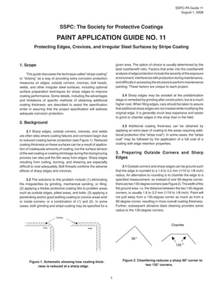
  • 1. SSPC-PA Guide 11 August 1, 2008 1 SSPC: The Society for Protective Coatings Paint Application Guide No. 11 Protecting Edges, Crevices, and Irregular Steel Surfaces by Stripe Coating 1. Scope This guide discusses the technique called “stripe coating” or “striping” as a way of providing extra corrosion protection measures on edges, outside corners, crevices, bolt heads, welds, and other irregular steel surfaces, including optional surface preparation techniques for sharp edges to improve coating performance. Some details, including the advantages and limitations of specific methods of obtaining additional coating thickness, are described to assist the specification writer in assuring that the project specification will address adequate corrosion protection. 2. Background 2.1 Sharp edges, outside corners, crevices, and welds are often sites where coating failures and corrosion begin due to reduced coating barrier protection (see Figure 1). Reduced coating thickness on these surfaces can be a result of applica- tion of inadequate amounts of coating, but the surface tension of the wet coating or coating shrinkage during the drying/curing process can also pull the film away from edges. Sharp edges resulting from cutting, burning, and shearing are especially difficult to coat adequately. Bolt threads combine the adverse effects of sharp edges and crevices. 2.2 The solutions to this problem include (1) eliminating the irregularities by grinding, mechanical sanding, or filing; (2) applying a thicker protective coating film to problem areas such as outside edges, pitted areas, and bolts; (3) applying a penetrating and/or good wetting coating to crevice areas and/ or inside corners; or a combination of (1) and (2). In some cases, both grinding and stripe coating may be specified for a given area. The option of choice is usually determined by the best cost/benefit ratio. Factors that enter into the cost/benefit analysisofedgeprotectionincludetheseverityoftheexposure environment,interferencewithproductionduringmaintenance, anddifficultyinaccessingthestructuretoperformmaintenance painting. These factors are unique to each project. 2.4 Sharp edges may be avoided at the prefabrication stage or remedied by grinding after construction, but at a much higher cost. When filing edges, care should be taken to assure that additional sharp edges are not created while modifying the original edge. It is generally much less expensive and easier to grind or chamfer edges in the shop than in the field. 2.5 Additional coating thickness can be obtained by applying an extra layer of coating to the areas requiring addi- tional protection (the “stripe coat”). In some cases, the “stripe coat” may be followed by the application of a full coat of a coating with edge retention properties. 3. Preparing Outside Corners and Sharp Edges 3.1 Outside corners and sharp edges can be ground such that the edge is rounded to a 1.6 to 3.2 mm (1/16 to 1/8 inch) radius. An alternative to rounding is to chamfer the edge to a specified measurement, so instead of one 90-degree corner, therearetwo135-degreecorners(seeFigure2).Thewidthofthe flat ground area, i.e. the distance between the two 135-degree corners, is usually 1.6 to 3.2 mm (1/16 to 1/8 inch). Paint will not pull away from a 135-degree corner as much as from a 90-degree corner, resulting in more overall coating thickness. Further, subsequent abrasive blast cleaning provides some radius to the 135-degree corners. Figure 1. Schematic showing how coating thick- ness is reduced at a sharp edge. 90° 135 ° Chamfer Figure 2. Chamfering reduces a sharp 90° corner to two 135° corners. Poor Coating Ideal
  • 2. SSPC- PA Guide 11 August 1, 2008 2 3.2 The increased performance resulting from rounding or chamfering edges depends on the service environment, the generic type of coating and on the radius or size of the chamfer. One research study1 showed that rounding or chamfering had no measurable effect if an ethyl silicate inorganic zinc-rich (IOZ) coating was applied over blast cleaned steel. Therefore, there is no need to go to the added expense of grinding edges if ethyl silicate IOZ coating is specified. However, the same study indicated that rounding or chamfering edges before application of an alkyd or organic zinc-rich primer improved the coating’s performance. Even with edge rounding or cham- fering, it is necessary that proper spray application techniques be used.2,3 The use of coatings with edge-retention properties (see Section 4.7.3) may also minimize or eliminate the need for edge grinding. 3.3 Edge grinding is best done in the shop before blast cleaning where the work is accessible. A sample statement in a specification may read, “All corners and edges shall be rounded to a 2 mm radius (1/16 inch) or ground to a 2 mm (1/16 inch) chamfer.” In addition to edges, rough surfaces are ground smooth. Flame cut edges are normally ground over their entire surface to remove the hardened surface layer resulting from flame cutting and permit creation of a profile. For immersion service and other services where increased corrosion can be expected, very rough welds should always be ground because many coatings cannot adequately protect them. NACE Standard RP0178 "Standard Recommended Practice: Fabrication Details, Surface Finish Requirements, and Proper Design Considerations for Tanks and Vessels to Be Lined for Immersion Service"4 provides guidance on finish requirements for welds. 4. Stripe Coat Application A “stripe coat” is a coat of paint applied only to edges, welds, outside corners, bolt heads and threads, and crevices, either before or after a full coat is applied to the entire surface. These areas are difficult to coat due to coating shrinkage during cure. Shrinkage pulls coating away from sharp edges, resulting in low dry film thickness. Wet coating may flow over rather than into crevices. This results in a temporary creating bridge over the crevice that disappears as the coating cures and shrinks, leaving the crevice interior unprotected. Both areas are susceptible to premature corrosion. The practice of applying a “stripe coat” to such areas is frequently referred to as “striping.” The project specification normally specifies the areas are to be striped, how to apply the stripe coat (brush or spray), in what order to apply the stripe coat (before or after the full coat), which coats are to be striped, whether tinting of the stripe coat or use of another color of coating is required, and information on the drying/curing requirements between application of the stripe and full coat (may defer to the coating manufacturer). 4.1AreastoStripe:Thefacilityownernormallydetermines whether stripe coating is warranted for some or all areas of the particular project. Sometimes only specified areas of outside corners, edges, welds, and crevices are striped. Situations where stripe coating is usually warranted are: Immersion service (e.g., interiors of fuel or water• storage tanks; ship hulls) Areas with high corrosion rates (e.g. cooling towers• and splash zones) Areas where access is difficult (e.g., towers, some• bridges). Built up members (e.g., lattice bars and boxes)• Situations where stripe coating may not be cost effective are: Non-critical components (e.g., interior wall in living• space on a ship) Mild exposure (e.g., SSPC environmental exposure• zones 1A and 1B(1),5 Inside corners (can be adequately covered using• proper spray technique) Areas that are usually stripe coated include: Crevices• Plate and sharp edges• Plate seams• Back-to-back angle seams (built up members)• Pitted steel• Bolt heads and nuts• Rivet heads• Welds• Other sharp discontinuities• Outside corners• • Stripe coating is most effective on edges that are either rounded or chamfered by grinding (see Section 3). 4.2 How to Stripe 4.2.1 Brushing is the preferred method of applying stripe coats. Unless otherwise specified, SSPC-PA 1 requires brush application of coatings to cracks, crevices, blind areas of all rivets and bolts, and all areas of limited access.(2),6 Brush application provides the highest quality stripe coat on most surfaces because it works the paint into the pores and crevices and allows the greatest control over the boundaries of the painted area. The coating should be allowed to dry to recoat according to the product data sheet before the full prime coat is applied. Coating manufacturers will usually provide guid- ance on the amount of dry time required before application of (1) SSPC Environmental Zone 1A–Interior, normally dry (or tem- porary protection). Very mild (oil base paints now last six years or more). SSPC Environmental Zone 1B–Exterior, normally dry (includes most areas where oil base paints now last six years or more)4 (2) SSPC-PA 1, Section 7.4.6.
  • 3. SSPC-PA Guide 11 August 1, 2008 3 subsequent coatings. Table 1 compares application of stripe coats by brush or spray. 4.2.2Whenapplyingastripecoat,thebrushstrokesshould run parallel to, not across, edges and crevices. Variations in pressure of the brush during application can result in thin film on sharp edges and accumulation of coating on adjoining perpendicularsurfaces.Toassureadequatefilmbuildonsharp edges, multiple brush applications may be necessary. Bolt heads and nuts should be striped in a circular brush motion. Striping should extend at least 3 centimeters (cm) (1 inch) from edges and other irregular surfaces. Round or oval brushes are generally considered most suitable for rivets, bolts, irregular surfaces, and rough or pitted steel. 4.2.3 SSPC-PA 1 does not permit rollers to be used to applycoatingsonirregularsurfaces,suchasrivets,boltheads, crevices, welds, corners or edges unless otherwise specified. (3) If the project specification permits the use of rollers for stripe coat application in these areas, PA 1 requires that the coating be brushed out to form a continuous and unbroken film over these surfaces. 4.2.4 Spraying the stripe coat can reduce the amount of time spent in brush application, but the painter has less control over the precise boundaries of the area being coated. Spray may be the best method for applying stripe coats using coatings with edge retention properties or zinc-rich coatings, or for applying a stripe coat to edges that have already been painted. The applicator should spray the coating along the flat surface, not directly at the edge itself, to prevent the atomiza- tion pressure from pushing the coating away from the edge that is to be protected. 3 SSPC-PA 1, Section 7.3.4. 4.2.5 When striping with a coating that is prone to pigment settling, such as zinc-rich primers, the coating in the pot should be constantly agitated, unless otherwise recommended by the coating manufacturer. 4.2.6Whenstripingwithamulti-componentthermosetting coating, the curing reaction will eventually progress to the point where the coating fails to wet the surface and level adequately. Sincehightemperaturesoftenacceleratecuringrates,thiseffect ismostpronouncedinhotweather.Heatofreaction(exotherm) may also be generated when multiple components of thermo- setting coatings are mixed, so it may be more cost effective to use smaller kits (e.g., 1-liter or 1-gallon units) rather than 5-liter or 5-gallon units. Note that most coating manufacturers prohibit mixing of partial kits. Thinning should not be used to restore the flow properties of a multi-component coating that has increased viscosity from partial curing. 4.2.7 It is good practice for the stripe coat to be a different color from the adjoining full coats or the bare steel surface. Thecolordifferenceenablespaintersandinspectorstovisually verify there are no misses, skips, or thin spots in the stripe coat. In addition, the application can be verified after the fact (as necessary) for thickness and proper coverage using a destruc- tive thickness gage (i.e., Tooke Gage), a holiday detector, or (on some specialty coatings) ultraviolet light. 4.3 What Coats to Stripe: Usually, a stripe application is specified for the primer coating because of the importance of complete coverage. After a surface has received its first coat of paint, there is less probability of incomplete coverage of subsequent coats. Occasionally, multiple stripe coats may be required over rough hand welds. In critical areas, the specifier TABLE 1 COMPARISON OF APPLICATION METHODS APPLICATION METHOD ADVANTAGES DISADVANTAGES Brush Best method to work paint into pores and• crevices Most complete coverage of rivet heads, bolt• heads, nuts, and threads Best control of extent of area coated• Most labor-intensive method• May pull incompletely cured paint from edge• Spray Fastest method of application• Least labor-intensive method• May be best method of applying coatings with• edge retention properties, zinc-rich coatings Quick method for applying a stripe coat to• edges al-ready painted May bridge (rather than penetrate into) pores and crev-• ices. Back-brushing needed to work wet coating into pits, crevices, and angles. More likely to miss areas in tight spaces, resulting in• holidays. Builds coating thickness on larger area (control of area• coated is difficult) More risk of overspray and dry spray•
  • 4. SSPC- PA Guide 11 August 1, 2008 4 may require that striping be done for two or more coats in a multi-coat system. Nevertheless, multiple coat striping is not commonly specified. 4.4 When to Stripe - Before or After Full Coat 4.4.1 Many coatings professionals feel that the stripe coat of the primer should be applied first to maximize corro- sion protection. For example, it is easier to work stripe coats into crevices that have not been bridged by a spray-applied full coat. However, there are several reasons why the stripe coat could be applied after the first full coat. If the stripe coat is applied prior to primer application, there is opportunity for the surrounding clean, unprotected steel to deteriorate while the stripe coat is drying/curing. Another reason is that stripe coating after application of the full coat (particularly an inter- mediate coat) will fill in pinholes and other holidays that have formed in the spray-applied coat. 4.4.2 If striping is specified for each coat in a multi-coat system, application of the stripe coat before the final finish coat will result in a more uniform finish. 4.4.3 When painting a tank floor or other surface subject to foot or vehicle traffic, it may be wise to delay application of the final stripe coat over the welds to minimize erosion of the coating by foot traffic or air hoses being dragged across the raised welds prior to the coating being put into service. 4.4.4 The advantages and limitations of striping before and after the full coat are summarized in Table 2. Final deter- mination of the best sequence of stripe coats and full coats will depend on the coating systems being used and the specific requirements of each project. 4.5 If the stripe coat is applied first, it is usually allowed to dry to touch (per ASTM D 1640) before the full coat is applied. However,therecanbeexceptionstothispractice.Therecoating instructions in the coating manufacturer’s product data sheet should be followed unless otherwise specified. 4.6 Controlling Thickness 4.6.1 The thickness of the stripe coat is difficult to control. Somecontractorswillmeasurethicknesstoassuretheminimum and maximum specified thickness limits have been satisfied, while others will make only a visual check for excessive build. For the most part, thickness is controlled by the skill of the applicatoranduseofawetfilmthickness(WFT)gage.However, notch gages cannot provide reliable WFTreadings on irregular surfaces and should not be used on edges. 4.6.2 Leeway on maximum thickness is usually allowed within 2 inches (5 cm) of an edge or 1 inch (3 cm) of a weld. Coatings may be tolerant of thickness beyond the specified upper limit. Near a striped area (2 inches [5 cm] from an edge and 1 inch [3 cm] from a weld), the maximum thickness is sometimesallowedtobetwicethenormalmaximum.Designers orspecifiersshouldusecoatingmanufacturer’srecommended dry film thickness (DFT) ranges as guidance for required thick- ness of a stripe coat. 4.6.3Conflictscanbeavoidedifthicknessrequirementsat or near the stripe coat and any allowed deviation from speci- fied minimum and maximum DFT thickness requirements are clearly stated in the project specification. 4.6.4 Although thickness of the stripe coat can often be measured in the immediate vicinity of an edge, it is very difficult to measure thickness of a coating over the edge itself. Some TABLE 2 ADVANTAGES AND LIMITATIONS OF STRIPING BEFORE VS. AFTER APPLICATION OF FULL COAT TIMING ADVANTAGES LIMITATIONS BEFORE Better application and protection of irregularities• Better appearance• Holidays, light spots are more obvious• Assists painter in monitoring progress• Rust-back of cleaned areas surrounding• the striped area may occur before full coat can be applied AFTER Surroundingblastcleanedsurfacewillnotrustwhile• stripe coat dries Can sometimes apply by spray (brush-back usually• required) Better coverage of pinholes and holidays• Can visually ensure that stripe coat has been• applied properly Damage to previously coated surfaces• may occur during application of stripe coat Higher chance of incomplete coverage of• irregularities Aesthetics (stripe coat may be more• visible)
  • 5. SSPC-PA Guide 11 August 1, 2008 5 electronic gages include very small tips (probes) to improve the reliability of dry film thickness readings taken on an edge. Notches in the probe tip aid in alignment of the gauge and thin flexible shims can be used to verify the accuracy of the gauge when measuring on an edge. 4.7 Coatings to Use for Striping 4.7.1 Welds and crevices are best protected when striped with a coating with good wetting properties. High build coat- ings are best for striping edges. However, it is impractical to specify two different stripe coatings on a job with edges, crevices and welds. The paint should be of a consistency to function on both surfaces. 4.7.2 The manufacturer should be consulted to determine the appropriate coating to use for the striping. If the stripe coat contains a zinc loading and is to be applied over a surface already primed with inorganic zinc, an organic zinc primer is used for the stripe coat, as inorganic zinc coatings do not bond well over themselves or over organic zinc. High solids coatings may have a relatively short dry time and may not possess good wetting properties, which is paramount to the success of the stripe coat. In this case, a compatible stripe coat with a slower drying time and improved wetting may be used with the high-solids coating. The coating selected for striping should be designed for the service environment. 4.7.3 Coatings with Edge Retention Properties: An alternative method for the protection of edges that may avoid the need for grinding and chamfering is the use of a coating that has edge retention properties. Typically these types of coatings are high-solids products that provide improved film thicknessretentionattheapexofanedgetoimproveprotection inthesecriticalareas.Amethodformeasuringtheedgeretention properties of a coating is published in MIL-PRF-23236C.7 This test method compares the film thickness of three specimens cut from a sample of coating applied to a non-chamfered 90 degree angle. The ratio of the film thickness at the apex vs. the film thickness on the flat area is calculated and expressed as the percentage of edge retention of the coating, as shown in Figure3.AccordingtoMIL-PRF-23236C,anyspecimenhaving less than 50 percent edge retention fails the test. An average value of 70 percent edge retention for three test specimens measured using an optical microscope is required to qualify a coating as having edge-retention properties. Note that very sharp edges, or “knife” edges, are very difficult to protect even with coatings with edge-retention properties. It is recommended that “knife” edges have their surface modified as described in Section 3 prior to coating to provide suitable corrosion protection. 5. Disclaimer 5.1 This guide is designed to describe, review, or analyze new or improved technology and does not meet the definition of a standard as defined by SSPC. A guide differs from a stan- dard in that it is not suitable for referencing in a specification or procurement document. SSPC guides are intended to provide consensus recommendations for best industry practice. They are not written as requirements that may be cited in a contract. However,specifiersmayincorporateinformationfromanSSPC guide into job-specific contract requirements. 5.2 While every precaution is taken to ensure that all informationfurnishedinSSPCguidesisasaccurate,complete, and useful as possible, SSPC cannot assume responsibility nor incur any obligation resulting from the use of any materials, coatings, or methods described herein, or of the guide itself. 5.3 This guide does not attempt to address problems concerning safety associated with its use. The user of this specification, as well as the user of all products or practices described herein, is responsible for instituting appropriate health and safety practices and for ensuring compliance with all governmental regulations. References 1. Corbett, W. D. “The Same Old Grind...An Investigation ofZinc-RichPrimerPerformanceOverSteelCorners.”Modern Steel Construction, Vol. 40, No. 6: p. 43-49. 2. Graco Publications, Airless Spray Techniques. Minne- apolis, MN: Graco Inc., 1993. This document is available as a downloadable .pdf file from http://www.graco.com. 3.GracoPublications,AirSprayTechniques.Minneapolis, MN: Graco Inc., 1995. This document is available as a down- loadable .pdf file from http://www.graco.com. 4. NACE Standard RP0178 (latest edition); Standard Recommended Practice: Fabrication Details, Surface Finish Requirements, and Proper Design Considerations for Tanks and Vessels to Be Lined for Immersion Service.” Measure paint thickness here (dft ) Measure paint thickness here (dft ) PAIN T PAIN T SU BSTR ATE flat Measure paint thickness here (dft )flat edge Figure 3. Diagram of edge retention test (courtesy of MIL-PRF-23236C) The edge retention percentage is calculated as: % Retention = dft (edge)/dft (flat) x 100
  • 6. SSPC- PA Guide 11 August 1, 2008 6 5. SSPC, “How to Use SSPC Standards and Guides.” Pittsburgh,PA:SSPC,2008.Houston,TX:NACEInternational. This standard is available from NACE International at http:// www.nace.org. 6. SSPC-PA 1 (latest edition), Shop, Field, and Mainte- nance Painting of Steel. Pittsburgh, PA: SSPC.This standard is available online at http:// www.sspc.org. 7. MIL-PRF-23236C (latest edition); Coating System for ShipStructures.WashingtonNavyYard,DC:NavalSeaSystems Command. This standard is available online at http://assist. daps.dla.mil/quicksearch