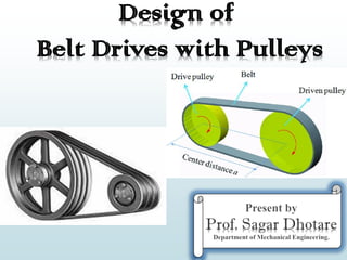
Design of Belt Drives With Pulley Theory By Prof. Sagar A. Dhotare
•
2 likes•1,883 views

It covers following points :- Introduction flat and V Belt Types of Belts Calculations for Tensions Maximum Torque Transmitted pulley design Advantage and disadvantages of V belt over flat belt

Recommended
More Related Content
What's hot
What's hot (20)
Similar to Design of Belt Drives With Pulley Theory By Prof. Sagar A. Dhotare
Similar to Design of Belt Drives With Pulley Theory By Prof. Sagar A. Dhotare (20)
More from Sagar Dhotare
More from Sagar Dhotare (20)
Recently uploaded
Recently uploaded (20)
Design of Belt Drives With Pulley Theory By Prof. Sagar A. Dhotare
- 1. Design of Belt Drives with Pulleys
- 2. Introduction Prof. Sagar A. Dhotare, Deparment of Mechanical Engineering, ViMEET. The belts are used to transmit power from one shaft to another by means of pulleys which rotate at the same speed or at different speeds. The amount of power transmitted depends upon the following factors : 1. The velocity of the belt. 2. The tension under which the belt is placed on the pulleys. 3. The arc of contact between the belt and the smaller pulley. 4. The conditions under which the belt is used. It may be noted that (a) The shafts should be properly in line to insure uniform tension across the belt section. (b) The pulleys should not be too close together, in order that the arc of contact on the smaller pulley may be as large as possible. (c) The pulleys should not be so far apart as to cause the belt to weigh heavily on the shafts, thus increasing the friction load on the bearings. (d) A long belt tends to swing from side to side, causing the belt to run out of the pulleys, which in turn develops crooked spots in the belt. (e) The tight side of the belt should be at the bottom, so that whatever sag is present on the loose side will increase the arc of contact at the pulleys. (f) In order to obtain good results with flat belts, the maximum distance between the shafts should not exceed 10 meters and the minimum should not be less than 3.5 times the diameter of the larger pulley.
- 3. Selection of a Belt Drive Prof. Sagar A. Dhotare, Deparment of Mechanical Engineering, ViMEET. Following are the various important factors upon which the selection of a belt drive depends: 1. Speed of the driving and driven shafts, 2. Speed reduction ratio, 3. Power to be transmitted, 4. Centre distance between the shafts, 5. Positive drive requirements, 6. Shafts layout, 7. Space available, 8. Service conditions
- 4. Types of Belt Drives Prof. Sagar A. Dhotare, Deparment of Mechanical Engineering, ViMEET. The belt drives are usually classified into the following three groups: 1. Light drives:- These are used to transmit small powers at belt speeds up to about 10 m/s as in agricultural machines and small machine tools. 2. Medium drives:- These are used to transmit medium powers at belt speeds over 10 m/s but up to 22 m/s, as in machine tools. 3. Heavy drives:- These are used to transmit large powers at belt speeds above 22 m/s as in compressors and generators.
- 5. Types of Belts Prof. Sagar A. Dhotare, Deparment of Mechanical Engineering, ViMEET. Though there are many types of belts used these days, yet the following are important from the subject point of view: 1. Flat belt:- The flat belt as shown in Fig.1 (a), is mostly used in the factories and workshops, where a moderate amount of power is to be transmitted, from one pulley to another when the two pulleys are not more than 8 meters apart. Fig. 1. Types of belts 2. V- belt:- The V-belt as shown in Fig.1 (b), is mostly used in the factories and workshops, where a great amount of power is to be transmitted, from one pulley to another, when the two pulleys are very near to each other. 3. Circular belt or rope:- The circular belt or rope as shown in Fig.1 (c) is mostly used in the factories and workshops, where a great amount of power is to be transmitted, from one pulley to another, when the two pulleys are more than 8 meters apart. If a huge amount of power is to be transmitted, then a single belt may not be sufficient. In such a case, wide pulleys (for V-belts or circular belts) with a number of grooves are used. Then a belt in each groove is provided to transmit the required amount of power from one pulley to another.
- 6. Material used for Belts Prof. Sagar A. Dhotare, Deparment of Mechanical Engineering, ViMEET. The material used for belts must be strong, flexible, and durable. It must have a high coefficient of friction. The belts, according to the material used, are classified as follows: 1. Leather belts :- The most important material for flat belt is leather. The best leather belts are made from 1.2 meters to 1.5 meters long strips cut from either side of the back bone of the top grade steer hides. The hair side of the leather is smoother and harder than the flesh side, but the flesh side is stronger. The fibers on the hair side are perpendicular to the surface, while those on the flesh side are interwoven and parallel to the surface. Therefore for these reasons the hair side of a belt should be in contact with the pulley surface as shown in Fig. 2. This gives a more intimate contact between belt and pulley and places the greatest tensile strength of the belt section on the outside, where the tension is maximum as the belt passes over the pulley. The leather may be either oak-tanned or mineral salt-tanned e.g. chrome-tanned. In order to increase the thickness of belt, the strips are cemented together. The belts are specified according to the number of layers e.g. single, double or triple ply and according to the thickness of hides used e.g. light, medium or heavy. Fig.2. Leather belts. The leather belts must be periodically cleaned and dressed or treated with a compound or dressing containing neat's foot or other suitable oils so that the belt will remain soft and flexible
- 7. Material used for Belts Prof. Sagar A. Dhotare, Deparment of Mechanical Engineering, ViMEET. 2. Cotton or fabric belts:- Most of the fabric belts are made by folding canvass or cotton duck to three or more layers (depending upon the thickness desired) and stitching together. These belts are woven also into a strip of the desired width and thickness. They are impregnated with some filler like linseed oil in order to make the belt water-proof and to prevent injury to the fibres. The cotton belts are cheaper and suitable in warm climates, in damp atmospheres and in exposed positions. Since the cotton belts require little attention, therefore these belts are mostly used in farm machinery, belt conveyor etc. 3. Rubber belt:- The rubber belts are made of layers of fabric impregnated with rubber composition and have a thin layer of rubber on the faces. These belts are very flexible but are quickly destroyed if allowed to come into contact with heat, oil or grease. One of the principle advantage of these belts is that they may be easily made endless. These belts are found suitable for saw mills, paper mills where they are exposed to moisture. 4. Balata belts:- These belts are similar to rubber belts except that balata gum is used in place of rubber. These belts are acid proof and water proof and it is not effected by animal oils or alkalies. The balata belts should not be at temperatures above 40°C because at this temperature the balata begins to soften and becomes sticky. The strength of balata belts is 25 per cent higher than rubber belts.
- 8. Working Stresses in Belts Prof. Sagar A. Dhotare, Deparment of Mechanical Engineering, ViMEET. The ultimate strength of leather belt varies from 21 to 35 MPa and a factor of safety may be taken as 8 to 10. However, the wear life of a belt is more important than actual strength. It has been shown by experience that under average conditions an allowable stress of 2.8 MPa or less will give a reasonable belt life. An allowable stress of 1.75 MPa may be expected to give a belt life of about 15 years. Density of Belt Materials The density of various belt materials are given in the following table. Belt Speed It is seen that when the speed of belt increases, the centrifugal force also increases which tries to pull the belt away from the pulley. This will result in the decrease of power transmitted by the belt. It has been found that for the efficient transmission of power, the belt speed 20 m/s to 22.5 m/s may be used.
- 9. Coefficient of Friction Between Belt and Pulley Prof. Sagar A. Dhotare, Deparment of Mechanical Engineering, ViMEET. The coefficient of friction between the belt and the pulley depends upon the following factors: 1. The material of belt; 2. The material of pulley; 3. The slip of belt; and 4. The speed of belt. According to C.G. Barth, the coefficient of friction (μ) for oak tanned leather belts on cast iron pulley, at the point of slipping, is given by the following relation, i.e. where v = Speed of the belt in meters per minute. The following table shows the values of coefficient of friction for various materials of belt and pulley.
- 10. Standard Belt Thicknesses and Widths Prof. Sagar A. Dhotare, Deparment of Mechanical Engineering, ViMEET. The standard flat belt thicknesses are 5, 6.5, 8, 10 and 12 mm. The preferred values of thicknesses are as follows: (a) 5 mm for nominal belt widths of 35 to 63 mm, (b) 6.5 mm for nominal belt widths of 50 to 140 mm, (c) 8 mm for nominal belt widths of 90 to 224 mm, (d) 10 mm for nominal belt widths of 125 to 400 mm, and (e) 12 mm for nominal belt widths of 250 to 600 mm. The standard values of nominal belt widths are in R10 series, starting from 25 mm upto 63 mm and in R 20 series starting from 71 mm up to 600 mm. Thus, the standard widths will be 25, 32, 40, 50, 63, 71, 80, 90, 100, 112, 125, 140, 160, 180, 200, 224, 250, 280, 315, 355, 400, 450, 500, 560 and 600 mm.
- 11. Belt Joints Prof. Sagar A. Dhotare, Deparment of Mechanical Engineering, ViMEET. When the endless belts are not available, then the belts are cut from big rolls and the ends are joined together by fasteners. The various types of joints are 1. Cemented joint, 2. Laced joint, 3. Hinged joint. The cemented joint, as shown in Fig.3 (a), made by the manufacturer to form an endless belt, is preferred than other joints. The laced joint is formed by punching holes in line across the belt, leaving a margin between the edge and the holes. A raw hide strip is used for lacing the two ends together to form a joint. This type of joint is known as straight-stitch raw hide laced joint, as shown in Fig. 3 (b). Metal laced joint as shown in Fig.3 (c), is made like a staple connection. The points are driven through the flesh side of the belt and clinched on the inside. Sometimes, metal hinges may be fastened to the belt ends and connected by a steel or fiber pin as shown in Fig.3 (d). Fig.3. Belt joints.
- 12. Belt Joints Prof. Sagar A. Dhotare, Deparment of Mechanical Engineering, ViMEET. The following table shows the efficiencies of these joints.
- 13. Types of Flat Belt Drives Prof. Sagar A. Dhotare, Deparment of Mechanical Engineering, ViMEET. The power from one pulley to another may be transmitted by any of the following types of belt drives. 1. Open belt drive:- The open belt drive, as shown in Fig. 18.4, is used with shafts arranged parallel and rotating in the same direction. In this case, the driver A pulls the belt from one side (i.e. lower side RQ) and delivers it to the other side (i.e. upper side LM). Thus the tension in the lower side belt will be more than that in the upper side belt. The lower side belt (because of more tension) is known as tight side whereas the upper side belt (because of less tension) is known as slack side, as shown in Fig.4. Fig.4. Open belt drive.
- 14. Types of Flat Belt Drives Prof. Sagar A. Dhotare, Deparment of Mechanical Engineering, ViMEET. 2. Crossed or twist belt drive:- The crossed or twist belt drive, as shown in Fig.5, is used with shafts arranged parallel and rotating in the opposite directions. In this case, the driver pulls the belt from one side (i.e. RQ) and delivers it to the other side (i.e. LM). Thus, the tension in the belt RQ will be more than that in the belt LM. The belt RQ (because of more tension) is known as tight side, whereas the belt LM (because of less tension) is known as slack side, as shown in Fig.5. Fig.5. Crossed or twist belt drive. A little consideration will show that at a point where the belt crosses, it rubs against each other and there will be excessive wear and tear. In order to avoid this, the shafts should be placed at a maximum distance of 20 b, where b is the width of belt and the speed of the belt should be less than 15 m/s.
- 15. Types of Flat Belt Drives Prof. Sagar A. Dhotare, Deparment of Mechanical Engineering, ViMEET. 3. Quarter turn belt drive:- The quarter turn belt drive (also known as right angle belt drive) as shown in Fig. 6 (a), is used with shafts arranged at right angles and rotating in one definite direction. In order to prevent the belt from leaving the pulley, the width of the face of the pulley should be greater or equal to 1.4 b, where b is width of belt. In case the pulleys cannot be arranged as shown in Fig.6 (a) or when the reversible motion is desired, then a quarter turn belt drive with a guide pulley, as shown in Fig.6 (b), may be used. Fig.6 Quarter turn belt drive
- 16. Types of Flat Belt Drives Prof. Sagar A. Dhotare, Deparment of Mechanical Engineering, ViMEET. 4. Belt drive with idler pulleys:- A belt drive with an idler pulley (also known as jockey pulley drive) as shown in Fig.7, is used with shafts arranged parallel and when an open belt drive can not be used due to small angle of contact on the smaller pulley. This type of drive is provided to obtain high velocity ratio and when the required belt tension can not be obtained by other means. Fig. 8. Belt drive with many idler pulleys.Fig.7. Belt drive with single idler pulley. When it is desired to transmit motion from one shaft to several shafts, all arranged in parallel, a belt drive with many idler pulleys, as shown in Fig.8, may be employed.
- 17. Types of Flat Belt Drives Prof. Sagar A. Dhotare, Deparment of Mechanical Engineering, ViMEET. 5. Compound belt drive:- A compound belt drive as shown in Fig. 9, is used when power is transmitted from one shaft to another through a number of pulleys. Fig. 9. Compound belt drive.
- 18. Types of Flat Belt Drives Prof. Sagar A. Dhotare, Deparment of Mechanical Engineering, ViMEET. 6. Stepped or cone pulley drive:- A stepped or cone pulley drive, as shown in Fig.10, is used for changing the speed of the driven shaft while the main or driving shaft runs at constant speed. This is accomplished by shifting the belt from one part of the steps to the other. Fig.10. Stepped or cone pulley drive.
- 19. Types of Flat Belt Drives Prof. Sagar A. Dhotare, Deparment of Mechanical Engineering, ViMEET. 7. Fast and loose pulley drive:- A fast and loose pulley drive, as shown in Fig.11, is used when the driven or machine shaft is to be started or stopped whenever desired without interfering with the driving shaft. A pulley which is keyed to the machine shaft is called fast pulley and runs at the same speed as that of machine shaft. A loose pulley runs freely over the machine shaft and is incapable of transmitting any power. When the driven shaft is required to be stopped, the belt is pushed on to the loose pulley by means of sliding bar having belt forks. Fig.11. Fast and loose pulley drive.
- 20. Velocity Ratio of a Belt Drive Prof. Sagar A. Dhotare, Deparment of Mechanical Engineering, ViMEET.
- 21. Slip of the Belt Prof. Sagar A. Dhotare, Deparment of Mechanical Engineering, ViMEET. The motion of belts and pulleys assuming a firm frictional grip between the belts and the pulleys. But sometimes, the frictional grip becomes insufficient. This may cause some forward motion of the driver without carrying the belt with it. This is called slip of the belt and is generally expressed as a percentage. The result of the belt slipping is to reduce the velocity ratio of the system. As the slipping of the belt is a common phenomenon, thus the belt should never be used where a definite velocity ratio is of importance (as in the case of hour, minute and second arms in a watch). Let s1 % = Slip between the driver and the belt, and s2 % = Slip between the belt and follower,
- 22. Creep of Belt Prof. Sagar A. Dhotare, Deparment of Mechanical Engineering, ViMEET.
- 23. Length of an Open Belt Drive Prof. Sagar A. Dhotare, Deparment of Mechanical Engineering, ViMEET. open belt drive, both the pulleys rotate in the same direction as shown in Fig.12. Let r1 and r2 = Radii of the larger and smaller pulleys, x = Distance between the centres of two pulleys (i.e. O1O2), L = Total length of the belt Fig. 12. Open belt drive. Let the belt leaves the larger pulley at E and G and the smaller pulley at F and H as shown in Fig. 12. Through O2 draw O2M parallel to FE. From the geometry of the figure, we find that O2M will be perpendicular to O1E. Let the angle MO2O1 = 𝛼 radians. We know that the length of the belt, L = Arc GJE + EF + Arc FKH + HG = 2 (Arc JE + EF + Arc FK) ...(i)
- 24. Length of an Open Belt Drive Prof. Sagar A. Dhotare, Deparment of Mechanical Engineering, ViMEET.
- 25. Length of an Open Belt Drive Prof. Sagar A. Dhotare, Deparment of Mechanical Engineering, ViMEET. L
- 26. Length of a Cross Belt Drive Prof. Sagar A. Dhotare, Deparment of Mechanical Engineering, ViMEET. In a cross belt drive, both the pulleys rotate in the opposite directions as shown in Fig. 13. Fig. 13 Crossed belt drive. Let r1 and r2 = Radii of the larger and smaller pulleys, x = Distance between the centers of two pulleys (i.e. O1O2 ), L = Total length of the belt. Let the belt leaves the larger pulley at E and G and the smaller pulley at F and H as shown in Fig.13. Through O2 draw O2M parallel to FE. From the geometry of the figure, we find that O2M will be perpendicular to O1E. Let the angle MO2O1 = α radians. We know that the length of the belt, L = Arc GJE + EF + Arc FKH + HG = 2 (Arc JE + FE + Arc FK) ...(i)
- 27. Length of a Cross Belt Drive Prof. Sagar A. Dhotare, Deparment of Mechanical Engineering, ViMEET.
- 28. Length of a Cross Belt Drive Prof. Sagar A. Dhotare, Deparment of Mechanical Engineering, ViMEET. The above expression is a function of (r1 + r2). It is thus obvious, that if sum of the radii of the two pulleys be constant, length of the belt required will also remain constant, provided the distance between centers of the pulleys remain unchanged.
- 29. Power Transmitted by a Belt Prof. Sagar A. Dhotare, Deparment of Mechanical Engineering, ViMEET. Fig. 14 shows the driving pulley (or driver) A and the driven pulley (or follower) B. As already discussed, the driving pulley pulls the belt from one side and delivers it to the other side. It is thus obvious that the tension on the former side (i.e. tight side) will be greater than the latter side (i.e. slack side) as shown in Fig. 14. Fig. 14 Power transmitted by a belt. Let T1 and T2 = Tensions in the tight side and slack side of the belt respectively in newton's, r1 and r2 = Radii of the driving and driven pulleys respectively in meters, ν = Velocity of the belt in m/s. The effective turning (driving) force at the circumference of the driven pulley or follower is the difference between the two tensions (i.e. T1 – T2). Work done per second = (T1 – T2) ν N-m/s and Power transmitted = (T1 – T2) ν W ... (Q 1 N-m/s = 1W) A little consideration will show that torque exerted on the driving pulley is (T1 – T2) r1 . Similarly, the torque exerted on the driven pulley is (T1 – T2) r2.
- 30. Ratio of Driving Tensions for Flat Belt Drive Prof. Sagar A. Dhotare, Deparment of Mechanical Engineering, ViMEET. Consider a driven pulley rotating in the clockwise direction as shown in Fig. 15. Let T1 = Tension in the belt on the tight side, T2 = Tension in the belt on the slack side, and θ = Angle of contact in radians (i.e. angle subtended by the arc AB, along which the belt touches the pulley, at the centre). Now consider a small portion of the belt PQ, subtending an angle δθ at the centre of the pulley as shown in Fig. 15. The belt PQ is in equilibrium under the following forces: 1. Tension T in the belt at P, 2. Tension (T + δT) in the belt at Q, 3. Normal reaction RN, and 4. Frictional force F = μ × RN, where μ is the coefficient of friction between the belt and pulley. Fig. 15 Ratio of driving tensions for flat belt.
- 31. Ratio of Driving Tensions for Flat Belt Drive Prof. Sagar A. Dhotare, Deparment of Mechanical Engineering, ViMEET.
- 32. Centrifugal Tension Prof. Sagar A. Dhotare, Deparment of Mechanical Engineering, ViMEET. Since the belt continuously runs over the pulleys, therefore, some centrifugal force is caused, whose effect is to increase the tension on both the tight as well as the slack sides. The tension caused by centrifugal force is called centrifugal tension. At lower belt speeds (less than 10 m/s), the centrifugal tension is very small, but at higher belt speeds (more than 10 m/s), its effect is considerable and thus should be taken into account. Consider a small portion PQ of the belt subtending an angle dθ at the centre of the pulley, as shown in Fig.16. Fig. 16 Centrifugal tension.
- 33. Centrifugal Tension Prof. Sagar A. Dhotare, Deparment of Mechanical Engineering, ViMEET.
- 34. Maximum Tension in the Belt Prof. Sagar A. Dhotare, Deparment of Mechanical Engineering, ViMEET. A little consideration will show that the maximum tension in the belt (T ) is equal to the total tension in the tight side of the belt (Tt1). Let σ = Maximum safe stress, b = Width of the belt, and t = Thickness of the belt. We know that the maximum tension in the belt, T = Maximum stress × Cross-sectional area of belt = σ.b.t When centrifugal tension is neglected, then T (or Tt1) = T1, i.e. Tension in the tight side of the belt. When centrifugal tension is considered, then T (or Tt1) = T1 + TC
- 35. Condition for the Transmission of Maximum Power Prof. Sagar A. Dhotare, Deparment of Mechanical Engineering, ViMEET.
- 36. Condition for the Transmission of Maximum Power Prof. Sagar A. Dhotare, Deparment of Mechanical Engineering, ViMEET.
- 37. Initial Tension in the Belt Prof. Sagar A. Dhotare, Deparment of Mechanical Engineering, ViMEET. When a belt is wound round the two pulleys (i.e. driver and follower), its two ends are joined together, so that the belt may continuously move over the pulleys, since the motion of the belt (from the driver) and the follower (from the belt) is governed by a firm grip due to friction between the belt and the pulleys. In order to increase this grip, the belt is tightened up. At this stage, even when the pulleys are stationary, the belt is subjected to some tension, called initial tension. When the driver starts rotating, it pulls the belt from one side (increasing tension in the belt on this side) and delivers to the other side (decreasing tension in the belt on that side). The increased tension in one side of the belt is called tension in tight side and the decreased tension in the other side of the belt is called tension in the slack side. Let T0 = Initial tension in the belt, T1 = Tension in the tight side of the belt, T2 = Tension in the slack side of the belt, and α = Coefficient of increase of the belt length per unit force. A little consideration will show that the increase of tension in the tight side = T1 – T0 and increase in the length of the belt on the tight side = α (T1 – T0) ...(i) Similarly, decrease in tension in the slack side = T0 – T2 and decrease in the length of the belt on the slack side = α (T0 – T2) ...(ii) Assuming that the belt material is perfectly elastic such that the length of the belt remains constant, when it is at rest or in motion, therefore increase in length on the tight side is equal to decrease in the length on the slack side. Thus, equating equations (i) and (ii), we have α (T1 – T0) = α (T0 – T2)
- 38. Initial Tension in the Belt Prof. Sagar A. Dhotare, Deparment of Mechanical Engineering, ViMEET.
- 39. Flat Belt Pulleys Prof. Sagar A. Dhotare, Deparment of Mechanical Engineering, ViMEET. The pulleys are used to transmit power from one shaft to another by means of flat belts, V-belts or ropes. Since the velocity ratio is the inverse ratio of the diameters of driving and driven pulleys, therefore the pulley diameters should be carefully selected in order to have a desired velocity ratio. The pulleys must be in perfect alignment in order to allow the belt to travel in a line normal to the pulley faces. The pulleys may be made of cast iron, cast steel or pressed steel, wood and paper. The cast materials should have good friction and wear characteristics. The pulleys made of pressed steel are lighter than cast pulleys, but in many cases they have lower friction and may produce excessive wear.
- 40. Types of Pulleys for Flat Belts Prof. Sagar A. Dhotare, Deparment of Mechanical Engineering, ViMEET. Following are the various types of pulleys for flat belts : 1. Cast iron pulleys, 2. Steel pulleys, 3. Wooden pulleys, 4. Paper pulleys, and 5. Fast and loose pulleys. 1. Cast Iron Pulleys :- Fig. 17 Solid cast iron pulleys. The pulleys are generally made of cast iron, because of their low cost. The rim is held in place by web from the central boss or by arms or spokes. The arms may be straight or curved as shown in Fig. 17 (a) and (b) and the cross-section is usually elliptical. When a cast pulley contracts in the mold, the arms are in a state of stress and very liable to break. The curved arms tend to yield rather than to break. The arms are near the hub.
- 41. Types of Pulleys for Flat Belts Prof. Sagar A. Dhotare, Deparment of Mechanical Engineering, ViMEET. Fig. 18. Split cast iron pulley. The cast iron pulleys are generally made with rounded rims. This slight convexity is known as crowning. The crowning tends to keep the belt in centre on a pulley rim while in motion. The crowning may be 9 mm for 300 mm width of pulley face. The cast iron pulleys may be solid as shown in Fig. 17 or split type as shown in Fig. 18. When it is necessary to mount a pulley on a shaft which already carrying pulleys etc. or have its ends swelled, it is easier to use a split-pulley. There is a clearance between the faces and the two halves are readily tightened upon the shafts by the bolts as shown in Fig. 18. A sunk key is used for heavy drives.
- 42. Types of Pulleys for Flat Belts Prof. Sagar A. Dhotare, Deparment of Mechanical Engineering, ViMEET. 2. Steel Pulleys :- Steel pulleys are made from pressed steel sheets and have great strength and durability. These pulleys are lighter in weight (about 40 to 60% less) than cast iron pulleys of the same capacity and are designed to run at high speeds. They present a coefficient of friction with leather belting which is at least equal to that obtained by cast iron pulleys. Steel pulleys are generally made in two halves which are bolted together. The clamping action of the hub holds the pulley to its shaft, thus no key is required except for most severe service. Steel pulleys are generally equipped with interchangeable bushings to permit their use with shafts of different sizes. The following table shows the number of spokes and their sizes according to Indian Standards, IS : 1691 – 1980 (Reaffirmed 1990).
- 43. Types of Pulleys for Flat Belts Prof. Sagar A. Dhotare, Deparment of Mechanical Engineering, ViMEET.
- 44. Types of Pulleys for Flat Belts Prof. Sagar A. Dhotare, Deparment of Mechanical Engineering, ViMEET. 3. Wooden Pulleys :- Wooden pulleys are lighter and possesses higher coefficient of friction than cast iron or steel pulleys. These pulleys have 2/3rd of the weight of cast iron pulleys of similar size. They are generally made from selected maple which is laid in segments and glued together under heavy pressure. They are kept from absorbing moisture by protective coatings of shellac or varnish so that warping may not occur. These pulleys are made both solid or split with cast iron hubs with keyways or have adjustable bushings which prevents relative rotation between them and the shaft by the frictional resistance set up. These pulleys are used for motor drives in which the contact arc between the pulley face and belt is restricted. 4. Paper Pulleys :- Paper pulleys are made from compressed paper fiber and are formed with a metal in the center. These pulleys are usually used for belt transmission from electric motors, when the center to center shaft distance is small.
- 45. Types of Pulleys for Flat Belts Prof. Sagar A. Dhotare, Deparment of Mechanical Engineering, ViMEET. 5. Fast and Loose Pulleys :- Fig. 19. Fast and loose pulley. A fast and loose pulley, as shown in Fig. 19, used on shafts enables machine to be started or stopped at will. A fast pulley is keyed to the machine shaft while the loose pulley runs freely. The belt runs over the fast pulley to transmit power by the machine and it is shifted to the loose pulley when the machine is not required to transmit power. By this way, stopping of one machine does not interfere with the other machines which run by the same line shaft. The loose pulley is provided with a cast iron or gun- metal bush with a collar at one end to prevent axial movement. The rim of the fast pulley is made larger than the loose pulley so that the belt may run slackly on the loose pulley. The loose pulley usually have longer hub in order to reduce wear and friction and it requires proper lubrication.
- 46. Design of Cast Iron Pulleys Prof. Sagar A. Dhotare, Deparment of Mechanical Engineering, ViMEET. The following procedure may be adopted for the design of cast iron pulleys. 1. Dimensions of pulley :- (i) The diameter of the pulley (D) may be obtained either from velocity ratio consideration or centrifugal stress consideration. We know that the centrifugal stress induced in the rim of the pulley, σt = ρ.ν2 Where ρ = Density of the rim material = 7200 kg/m3 for cast iron ν = Velocity of the rim = πDN / 60, D being the diameter of pulley and N is speed of the pulley. The following are the diameter of pulleys in mm for flat and V-belts. 20, 22, 25, 28, 32, 36, 40, 45, 50, 56, 63, 71, 80, 90, 100, 112, 125, 140, 160, 180, 200, 224, 250, 280, 315, 355, 400, 450, 500, 560, 630, 710, 800, 900, 1000, 1120, 1250, 1400, 1600, 1800, 2000, 2240, 2500, 2800, 3150, 3550, 4000, 5000, 5400. The first six sizes (20 to 36 mm) are used for V-belts only. (ii) If the width of the belt is known, then width of the pulley or face of the pulley (B) is taken 25% greater than the width of belt. ∴ B = 1.25 b ; where b = Width of belt. According to Indian Standards, IS : 2122 (Part I) – 1973 (Reaffirmed 1990), the width of pulley is fixed as given in the following table :
- 47. Design of Cast Iron Pulleys Prof. Sagar A. Dhotare, Deparment of Mechanical Engineering, ViMEET. 2. Dimensions of arms (i) The number of arms may be taken as 4 for pulley diameter from 200 mm to 600 mm and 6 for diameter from 600 mm to 1500 mm. Note : The pulleys less than 200 mm diameter are made with solid disc instead of arms. The thickness of the solid web is taken equal to the thickness of rim measured at the center of the pulley face. (ii) The cross-section of the arms is usually elliptical with major axis (a1) equal to twice the minor axis (b1). The cross-section of the arm is obtained by considering the arm as cantilever i.e. fixed at the hub end and carrying a concentrated load at the rim end. The length of the cantilever is taken equal to the radius of the pulley. It is further assumed that at any given time, the power is transmitted from the hub to the rim or vice versa, through only half the total number of arms.
- 48. Design of Cast Iron Pulleys Prof. Sagar A. Dhotare, Deparment of Mechanical Engineering, ViMEET. Fig. 20. Cast iron pulley with two rows of arms. (iii) The arms are tapered from hub to rim. The taper is usually 1/48 to 1/32. (iv) When the width of the pulley exceeds the diameter of the pulley, then two rows of arms are provided, as shown in Fig. 20. This is done to avoid heavy arms in one row.
- 49. Design of Cast Iron Pulleys Prof. Sagar A. Dhotare, Deparment of Mechanical Engineering, ViMEET.
- 50. V-Belt Drive Prof. Sagar A. Dhotare, Deparment of Mechanical Engineering, ViMEET. V-belt is mostly used in factories and workshops where a great amount of power is to be transmitted from one pulley to another when the two pulleys are very near to each other. The V-belts are made of fabric and cords moulded in rubber and covered with fabric and rubber as shown in Fig. 21 (a). These belts are moulded to a trapezoidal shape and are made endless. These are particularly suitable for short drives. The included angle for the V-belt is usually from 30° to 40°. The power is transmitted by the wedging action between the belt and the V-groove in the pulley or sheave. The wedging action of the V-belt in the groove of the pulley results in higher forces of friction. A little consideration will show that the wedging action and the transmitted torque will be more if the groove angle of the pulley is small. But a small groove angle will require more force to pull the belt out of the groove which will result in loss of power and excessive belt wear due to friction and heat. Hence the selected groove angle is a compromise between the two. Usually the groove angles of 32° to 38° are used. Fig. 21. V-Belt and V-grooved pulley.
- 51. V-Belt Drive Prof. Sagar A. Dhotare, Deparment of Mechanical Engineering, ViMEET. A clearance must be provided at the bottom of the groove as shown in Fig. 21 (b), in order to prevent touching of the bottom as it becomes narrower from wear. The V-belt drive may be inclined at any angle with tight side either at top or bottom. In order to increase the power output, several V-belts may be operated side by side. It may be noted that in multiple V-belt drive, all the belts should stretch at the same rate so that the load is equally divided between them. When one of the set of belts break, the entire set should be replaced at the same time. If only one belt is replaced, the new unworn and unstretched belt will be more tightly stretched and will move with different velocity.
- 52. Types of V-belts and Pulleys Prof. Sagar A. Dhotare, Deparment of Mechanical Engineering, ViMEET. According to Indian Standards (IS: 2494 – 1974), the V-belts are made in five types i.e. A, B, C, D and E. The dimensions for standard V-belts are shown in Table 1. The pulleys for V-belts may be made of cast iron or pressed steel in order to reduce weight. The dimensions for the standard V- grooved pulley according to IS: 2494 – 1974, are shown in Table According to Indian Standards (IS: 2494 – 1974), the V-belts are made in five types i.e. A, B, C, D and E. The dimensions for standard V- belts are shown in below table. The pulleys for V-belts may be made of cast iron or pressed steel in order to reduce weight. The dimensions for the standard V-grooved pulley according to IS: 2494 – 1974, are shown in Table 2. Table 1. Dimensions of standard V-belts according to IS: 2494 – 1974. Table 2. Dimensions of standard V-grooved pulleys according to IS : 2494–1974. (All dimensions in mm) Face width (B) = (n – 1) e + 2 f
- 53. Standard Pitch Lengths of V-belts Prof. Sagar A. Dhotare, Deparment of Mechanical Engineering, ViMEET. According to IS: 2494-1974, the V-belts are designated by its type and nominal inside length. For example, a V-belt of type A and inside length 914 mm is designated as A 914–IS: 2494. The standard inside lengths of V-belts in mm are as follows : 610, 660, 711, 787, 813, 889, 914, 965, 991, 1016, 1067, 1092, 1168, 1219, 1295, 1372, 1397, 1422, 1473, 1524, 1600, 1626, 1651, 1727, 1778, 1905, 1981, 2032, 2057, 2159, 2286, 2438, 2464, 2540, 2667, 2845, 3048, 3150, 3251, 3404, 3658, 4013, 4115, 4394, 4572, 4953, 5334, 6045, 6807, 7569, 8331, 9093, 9885, 10 617, 12 141, 13 665, 15 189, 16 713 According to IS: 2494-1974, the pitch length is defined as the circumferential length of the belt at the pitch width (i.e. the width at the neutral axis) of the belt. The value of the pitch width remains constant for each type of belt irrespective of the groove angle. The pitch lengths are obtained by adding to inside length: 36 mm for type A, 43 mm for type B, 56 mm for type C, 79 mm for type D and 92 mm for type E. The following table shows the standard pitch lengths for the various types of belt.
- 54. Standard Pitch Lengths of V-belts Prof. Sagar A. Dhotare, Deparment of Mechanical Engineering, ViMEET. The V-belts are also manufactured in non-standard pitch lengths (i.e. in oversize and undersize). The standard pitch length belt is designated by grade number 50. The oversize belts are designated by a grade number more than 50, while the undersize belts are designated by a grade number less than 50. It may be noted that one unit of a grade number represents 2.5 mm in length from nominal pitch length. For example, a V-belt marked A – 914 – 50 denotes a standard belt of inside length 914 mm and a pitch length 950 mm. A belt marked A – 914 – 52 denotes an oversize belt by an amount of (52 – 50) = 2 units of grade number. Since one unit of grade number represents 2.5 mm, therefore the pitch length of this belt will be 950 + 2 × 2.5 = 955 mm. Similarly, a belt marked A – 914 – 48 denotes an undersize belt, whose pitch length will be 950 – 2 × 2.5 = 945 mm.
- 55. Ratio of Driving Tensions for V-belt Prof. Sagar A. Dhotare, Deparment of Mechanical Engineering, ViMEET. Fig. 22. V-belt with pulley. A V-belt with a grooved pulley is shown in Fig. 22. Let R1 = Normal reactions between belts and sides of the groove. R = Total reaction in the plane of the groove. μ = Coefficient of friction between the belt and sides of the groove. Resolving the reactions vertically to the groove, we have R = R1 sin β + R1 sin β = 2R1 sin β Consider a small portion of the belt subtending an angle δθ at the centre, the tension on one side will be T and on the other side (T + δT). Now proceeding in the same way as flat belt, we get the frictional resistance equal to μ R. cosec β against μ.R. Thus the relation between T1 and T2 for the V-belt drive will be 2.3 log (T1 / T2) = μ.θ cosec β
- 56. Advantages and Disadvantages of V-belt Drive over Flat Belt Drive Prof. Sagar A. Dhotare, Deparment of Mechanical Engineering, ViMEET. Advantages 1. The V-belt drive gives compactness due to the small distance between centres of pulleys. 2. The drive is positive, because the slip between the belt and the pulley groove is negligible. 3. Since the V-belts are made endless and there is no joint trouble, therefore the drive is smooth. 4. It provides longer life, 3 to 5 years. 5. It can be easily installed and removed. 6. The operation of the belt and pulley is quiet. 7. The belts have the ability to cushion the shock when machines are started. 8. The high velocity ratio (maximum 10) may be obtained. 9. The wedging action of the belt in the groove gives high value of limiting ratio of tensions. Therefore the power transmitted by V-belts is more than flat belts for the same coefficient of friction, arc of contact and allowable tension in the belts. 10. The V-belt may be operated in either direction, with tight side of the belt at the top or bottom. The centre line may be horizontal, vertical or inclined.
- 57. Advantages and Disadvantages of V-belt Drive over Flat Belt Drive Prof. Sagar A. Dhotare, Deparment of Mechanical Engineering, ViMEET. Disadvantages :- 1. The V-belt drive can not be used with large centre distances, because of larger weight per unit length. 2. The V-belts are not so durable as flat belts. 3. The construction of pulleys for V-belts is more complicated than pulleys of flat belts. 4. Since the V-belts are subjected to certain amount of creep, therefore these are not suitable for constant speed applications such as synchronous machines and timing devices. 5. The belt life is greatly influenced with temperature changes, improper belt tension and mismatching of belt lengths. 6. The centrifugal tension prevents the use of V-belts at speeds below 5 m/ s and above 50 m / s.