

Recommended
More Related Content
What's hot
What's hot (20)
Viewers also liked
Viewers also liked (20)
Similar to Lecture10 mohr's circle
Similar to Lecture10 mohr's circle (20)
Recently uploaded
Recently uploaded (20)
Lecture10 mohr's circle
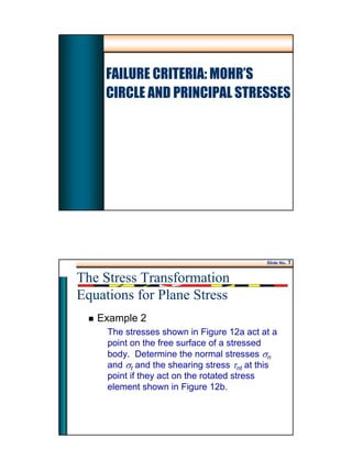
- 1. 1 FAILURE CRITERIA: MOHR’S CIRCLE AND PRINCIPAL STRESSES Slide No. 1 Example 2 The stresses shown in Figure 12a act at a point on the free surface of a stressed body. Determine the normal stresses σn and σt and the shearing stress τnt at this point if they act on the rotated stress element shown in Figure 12b. The Stress Transformation Equations for Plane Stress
- 2. 2 Slide No. 2 The Stress Transformation Equations for Plane Stress Example 2 (cont’d) MPa70 MPa40 MPa10 nσ tσ ntτ 0 15 nt Figure 12 (a) (b) Slide No. 3 The Stress Transformation Equations for Plane Stress Example 2 (cont’d) The given values are as follows: 000 t 0 1059015,15 MPa40MPa,70MPa,10 =+== +=−=−= θθ τσσ n xyyx nσ tσ ntτ 0 15 nt t 0 15 0 90 n
- 3. 3 Slide No. 4 The Stress Transformation Equations for Plane Stress Example 2 (cont’d) Applying Eq. 12 for the given values ( ) ( ) ( ) ( ) (Tension)MPa981.5MPa981.5 15cos15sin)40(215sin7015cos10 cossin2sincos 22 22 == +−−= ++= n xyyxn σ θθτθσθσσ ( ) ( ) ( ) ( ) n)(comprssioMPa86MPa98.85 105cos105sin)40(2105sin70105cos10 cossin2sincos 22 22 =−= +−−= ++= t xyyxt σ θθτθσθσσ Slide No. 5 The Stress Transformation Equations for Plane Stress Example 2 (cont’d) ( ) ( ) ( ) ( ) ( )( ) MPa64.19 15sin15cos40)15cos()15sin()70(10 sincoscossin 22 22 = −+−−−−= −+−−= nt xyyxnt τ θθτθθσστ MPa70 MPa40 MPa10 MPa98.5=nσ MPa86=tσ MPa64.19=ntτ 0 15 nt
- 4. 4 Slide No. 6 Principal Stresses and Maximum Shearing Stress Principal Stresses – The transformation equations (Eq. 12 or 13) provides a means for determining the normal stress σn and the shearing stress τnt on different planes through a point O in stressed body. – Consider, for example, the state of stress at a point O of the free surface of a structure or machine component (Fig. 13). Slide No. 7 Principal Stresses and Maximum Shearing Stress Principal Stresses x y z (b) ksi7 ksi12 ksi25⋅ o (a) ⋅ Surfaces perpendicular to z-axis are stress-free. Figure 13
- 5. 5 Slide No. 8 Principal Stresses and Maximum Shearing Stress Principal Stresses – As the element is rotated through an angle θ about an axis perpendicular to the stress- free surface, the normal stress σn and the shearing stressτnt on different planes vary continuously as shown in Figure 14. – For design purposes, critical stress at the point are usually the maximum tensile (or compressive) and shearing stresses. Slide No. 9 Principal Stresses and Maximum Shearing Stress Principal Stresses – The principal stresses are the maximum normal stress σmax and minimum normal stress σmin. – In general, these maximum and minimum or principal stresses can be determined by plotting curves similar to those of Fig. 14. – But this process is time-consuming, and therefore, general methods are needed.
- 6. 6 Slide No. 10 Principal Stresses and Maximum Shearing Stress Variation of Stresses as Functions of θ -20 -10 0 10 20 30 40 0 60 120 180 240 300 360 Angle θ (Degrees) Stress(Ksi) Stress sn Stress tnt nt n τ σ ksi12 ksi7 ksi25 x y nt θ Figure 14 Slide No. 11 ENES 220 ©Assakkaf Principal Stresses and Maximum Shearing Stress Principal Stresses – Principal Stresses for Special Loading Conditions: • Bar under axial load • Shaft under Pure Bending A P A P 2 and maxmax == τσ (14) J cTmax maxmax ==τσ (15)
- 7. 7 Slide No. 12 Principal Stresses and Maximum Shearing Stress Principal Stresses for Axially Loaded Bar θ P P F Original Area, A Inclined Area, An Figure 15 Slide No. 13 Principal Stresses and Maximum Shearing Stress Principal Stresses for Axially Loaded Bar P N V θ θ θ θ θ cos sin cos A A PV PN n = = = θ ( )θθ θ θ σ 2cos1 2 cos cos cos 2 +==== A P A P A P A N n n Figure 16a
- 8. 8 Slide No. 14 Principal Stresses and Maximum Shearing Stress Principal Stresses for Axially Loaded Bar P N V θ θ θ θ θ cos sin cos A A PV PN n = = = θ θθθ θ θ τ 2sin 2 cossin cos sin A P A P A P A V n n ==== Figure 16b Slide No. 15 Principal Stresses for Axially Loaded Bar σn is maximum when θ = 00 or 1800 τn is maximum when θ = 450 or 1350 – Also Therefore 2 max max σ τ = A P A P 2 and maxmax == τσ (16) (17) Principal Stresses and Maximum Shearing Stress
- 9. 9 Slide No. 16 Principal Stresses and Maximum Shearing Stress Principal Stresses for Shaft under Pure Torsion x y A x y xyτ xyτ yxτ yxτ (a) (b) x yt α α n σn dA τn t dA α τyx dA sin α τxydAcosα (c) Fig.17 Slide No. 17 Principal Stresses and Maximum Shearing Stress Principal Stresses for Shaft under Pure Torsion yt α n σn dA τn t dA α τyx dA sin α τxydAcosα ( ) ατααττ 2cossincos 22 xyxynt =−= (18)αταατσ 2sincossin2 xyxyn == (19) J cTmax maxmax ==τσ (20)
- 10. 10 Slide No. 18 Principal Stresses and Maximum Shearing Stress Development of Principal Stresses Equations Recall Eq 13 θτθ σσ τ 2cos2sin 2 xy yx nt + − −= θτθ σσσσ σ 2sin2cos 22 xy yxyx n + − + + = (13a) (13b) Slide No. 19 Principal Stresses and Maximum Shearing Stress Development of Principal Stresses Equations Differentiating the first equation with respect to θ and equate the result to zero, gives ( ) 02cos22sin 2sin2cos 22 =+−−= + − + + = θτθσσ θτθ σσσσ θθ xyyx xy yxyxn d d d dσ 2 tan2or 2 2tan or 1 − = − = − yx xy p yx xy p σσ τ θ σσ τ θ (21) set
- 11. 11 Slide No. 20 Principal Stresses and Maximum Shearing Stress Development of Principal Stresses Equations Substituting the expression for 2θp into Eq. 13a, yields Eq. 21 gives the two principal stresses in the xy-plane, and the third stress σp3 = σz = 0. 2 2 2,1 22 xy yxyx pp τ σσσσ σ + − ± + = (22) Slide No. 21 Principal Stresses and Maximum Shearing Stress Principal Stresses Principal stresses σmax and σmin can be computed from where subscript p refers to the planes of maximum and minimum values of σn. 2 2 2,1 22 xy yxyx pp τ σσσσ σ + − ± + = (22a)
- 12. 12 Slide No. 22 Principal Stresses and Maximum Shearing Stress Location of the Plane of Principal Stresses 2 tan 2 1 1 − = − yx xy p σσ τ θ (22b) Slide No. 23 Principal Stresses and Maximum Shearing Stress Notes on Principal Stresses Equation 1. Eq. 22 gives the angle θp and θp + 900 between x-plane (or y-plane) and the mutually perpendicular planes on which the principal stresses act. 2. When tan 2θp is positive, θp is positive, and the rotation is counterclockwise from the x- and y-planes to the planes on which the two principal stresses act.
- 13. 13 Slide No. 24 Principal Stresses and Maximum Shearing Stress Notes on Principal Stresses Equation 3. When tan 2θp is negative, θp is negative, and the rotation is clockwise. 4. The shearing stress is zero on planes experiencing maximum and minimum values of normal stresses. 5. If one or both of the principal stresses from Eq.22 is negative, the algebraic maximum stress can have a smaller absolute value than the minimum stress. Slide No. 25 Development of Maximum Shearing Stress Equation Recall Eq 13b: θτθ σσ τ 2cos2sin 2 xy yx nt + − −= ( ) 02sin22cos 2cos2sin 2 =−−−= + − −= θτθσσ θτθ σσ θθ τ xyyx xy yxnt d d d d 2 tan2or 2 2tan or 1 − = − −= − xy yx xy yx τ σσ θ τ σσ θ ττ set (23) Principal Stresses and Maximum Shearing Stress
- 14. 14 Slide No. 26 Development of Principal Shearing Stress Equation Substituting the expression for 2θτ into Eq. 13b, yields Eq. 24 gives the maximum in-plane shearing stress. 2 2 2 xy yx p τ σσ τ + − ±= (24) Principal Stresses and Maximum Shearing Stress Slide No. 27 Maximum In-Plane Shearing Stress Maximum in-plane shearing stress can be computed from where the subscript p refers to the plane of maximum in-plane shearing stress τp. (24a)2 2 2 xy yx p τ σσ τ + − ±= Principal Stresses and Maximum Shearing Stress
- 15. 15 Slide No. 28 Principal Stresses and Maximum Shearing Stress Location of the Plane of Maximum Shearing Stress 2 tan 2 1 1 − = − xy yx τ σσ θτ (24b) Slide No. 29 Principal Stresses and Maximum Shearing Stress Notes on Principal Stresses and Maximum In-Plane Shearing Stress Equation 1. The two angles 2θp and 2θτ differ by 900, therefore, θp and θτ are 450 apart. 2. This means that the planes in which the maximum in-plane shearing stress occur are 450 from the principal planes.
- 16. 16 Slide No. 30 Principal Stresses and Maximum Shearing Stress Notes on Principal Stresses and Maximum In-Plane Shearing Stress Equation 3. The direction of the maximum shearing stress can be determined by drawing a wedge-shaped block with two sides parallel to the planes having the maximum and minimum principal stresses, and with the third side at an angle of 450. The direction of the maximum shearing stress must oppose the larger of the two principal stresses. Slide No. 31 pθ xyτ xσ pθ yσ 1pσ 2pσ nσ maxτ maxτ nσ 1pσ 2pσ 21 Pp σσ > 0 45 0 45 x y Wedge-shaped BlockFig.18 Principal Stresses and Maximum Shearing Stress
- 17. 17 Slide No. 32 Principal Stresses and Maximum Shearing Stress Useful Relationships • The maximum value of τnt is equal to one half the difference between the two in-plane principal stresses, that is • For plane stress, the sum of the normal stresses on any two orthogonal planes through a point in a body is a constant or in invariant. 2 21 pp p σσ τ − = yxpp σσσσ +=+ 21 (25) (26) Slide No. 33 Principal Stresses and Maximum Shearing Stress Useful Relationships – When a state of plane exists, one of the principal stresses is zero. – If the values of σp1 and σp2 from Eq. 25 have the same sign, then the third principal stress σp3 equals zero, will be either the maximum or minimum normal stresses. – Three possibilities: ( ) ( ) ( ) 2/0max,2/0max,2/max 2121 pppp σσσσ −=−=−=
- 18. 18 Slide No. 34 Principal Stresses and Maximum Shearing Stress Example 3 Normal and shearing stresses on horizontal and vertical planes through a point in a structural member subjected to plane stress are shown in Figure 19. Determine and show on a sketch the principal and maximum shearing stresses. Slide No. 35 Principal Stresses and Maximum Shearing Stress Example 3 (cont’d) ksi4 ksi12 ksi6 Fig.19 The given values for use in Eqs. 22 and 24 are: σx = +12 ksi σy = - 4 ksi τxy = - 6 ksi
- 19. 19 Slide No. 36 Principal Stresses and Maximum Shearing Stress Example 3 (cont’d) Using Eq. 22a for the given values: Therefore, ( ) ( ) 1046 2 412 2 )4(12 22 2 2 2 2 ±=−+ −− ± −+ = + − ± + = xy yxyx p τ σσσσ σ 0 (C)ksi6ksi6104 (T)ksi14ksi14104 3 2 1 == =−=−= =+=+= zp p P σσ σ σ Slide No. 37 Principal Stresses and Maximum Shearing Stress Example 3 (cont’d) Since the σp1 and σp2 have opposite sign, the maximum shearing stress is The location θp of the principal stresses is computed from Eq. 22b ( ) ksi10 2 20 2 614 2 21 max +== −− = − = pp σσ τ ( ) ( ) 01 18.43 412 62 tan 2 1 = −− − = − yx pθ
- 20. 20 Slide No. 38 Principal Stresses and Maximum Shearing Stress Example 3 (cont’d) Sketch of principal and max shearing stressesksi6 ksi12 0 43.18 ksi4 ksi10 ksi4 ksi14 ksi6 0 45 x y ksi6 maxksi10 ττ ==p (T)ksi4 2 412 2 = − = + = yx n σσ σ Slide No. 39 Principal Stresses and Maximum Shearing Stress Example 4 Normal and shearing stresses on horizontal and vertical planes through a point in a structural member subjected to plane stress are shown in Figure 20. Determine and show on a sketch the principal and maximum shearing stresses
- 21. 21 Slide No. 40 Principal Stresses and Maximum Shearing Stress Example 4 (cont’d) MPa36 MPa72 MPa24 Fig.20 The given values for use in Eqs. 22 and 24 are: σx = +72 MPa σy = +36 MPa τxy = - 24 MPa Slide No. 41 Example 4 (cont’d) Using Eq. 22a for the given values: Therefore, ( ) ( ) 305424 2 3672 2 )36(72 22 2 2 2 2 ±=−+ +− ± ++ = + − ± + = xy yxyx p τ σσσσ σ 0 (T)MPa24ksi243054 (T)MPa84ksi843054 3 2 1 == =+=−= =+=+= zp p P σσ σ σ Principal Stresses and Maximum Shearing Stress
- 22. 22 Slide No. 42 Example 4 (cont’d) Since the σp1 and σp2 have the same sign, the maximum shearing stress is The location θp of the principal stresses is computed from Eq. 22b MPa42 2 84 2 084 2 01 max +== − = − = pσ τ 011 57.26 3672 )24(2 tan 2 12 tan 2 1 −= − − = − = −− yx xy p σσ τ θ Principal Stresses and Maximum Shearing Stress Slide No. 43 Example 4 (cont’d) Sketch of principal and max shearing stressesksi6 MPa72 0 57.26 MPa36 MPa30 MPa54 MPa84 MPa24 0 45 x y MPa24 MPa42 MPa30 2 2484 2 max 21 max = = − = − = ≠ τ σσ τ ττ pp p p (T)MPa54 2 3672 2 = + = + = yx n σσ σ 0 45 MPa42 MPa84 03 =pσ MPa42 Principal Stresses and Maximum Shearing Stress
- 23. 23 Slide No. 44 Mohr’s Circle for Plane Stress Introduction – Mohr’s circle is a pictorial or graphical interpretation of the transformation equations for plane stress. – The process involves the construction of a circle in such a manner that the coordinates of each point on the circle represent the normal and shearing stresses on one plane through the stressed Slide No. 45 ENES 220 ©Assakkaf Maximum Shearing Stress Maximum shearing stress occurs for avex σσ =′ 2 45byfromoffset and90byseparatedanglestwodefines:Note 2 2tan 2 o o 2 2 max yx ave p xy yx s xy yx R σσ σσ θ τ σσ θ τ σσ τ + ==′ − −= + − ==
- 24. 24 Slide No. 46 Mohr’s Circle for Plane Stress Introduction Point, and the angular position of the radius to the point gives the orientation of the plane. – The proof that normal and shearing components of stress on arbitrary plane through a point can be represented as points on a circle follows from Eqs. 13a and 13b. Slide No. 47 Mohr’s Circle for Plane Stress Plane Stresses using Mohr’s Circle • Recall Eqs. 13a and 13b, • Squaring both equations, adding, and simplifying gives θτθ σσ τ 2cos2sin 2 xy yx nt + − −= θτθ σσσσ σ 2sin2cos 22 xy yxyx n + − + + = (13a) (13a) 2 2 2 2 22 xy yxyx n nt τ σσ τ σσ σ + − =+ + − (27)
- 25. 25 Slide No. 48 Mohr’s Circle for Plane Stress Plane Stresses using Mohr’s Circle – The previous equation is indeed an equation of a circle in terms of the variable σn and τnt. The circle is centered on the the σ axis at a distance (σx - σy)/2 from the τ axis, and the radius of the circle is given by 2 2 2 xy yx R τ σσ + − = (28) Slide No. 49 Mohr’s Circle for Plane Stress Plane Stresses using Mohr’s Circle – Normal stresses are plotted as horizontal coordinates, with tensile stresses (positive) plotted to the right of the origin and compressive stresses (negative) plotted to the left. – Shearing stresses are plotted as vertical coordinates, with those tending to produce a clockwise rotation of the stress element
- 26. 26 Slide No. 50 Mohr’s Circle for Plane Stress Plane Stresses using Mohr’s Circle plotted above the σ-axis, and those tending to produce counterclockwise rotation of the stress element plotted below the σ-axis. – Sign conventions for interpreting the normal and shearing stresses will be provided, and illustrated through examples. Slide No. 51 Mohr’s Circle for Plane Stress Plane Stresses using Mohr’s Circle • Mohr’s circle for any point subjected to plane stress can be drawn when stresses on two mutually perpendicular planes through the point are known. x y n t θ yσ xσ xyτ yxτ xyτ yxτ xσ yσ A A θ
- 27. 27 Slide No. 52 Mohr’s Circle for Plane Stress Mohr’s Circle yxτ yσ 2pσ 2 yx σσ + xσ nσ 1pσ τ σ θ2 pθ2 pτ ntτ xyτ 2 yx σσ − ),( yxyH τσ ),( xyxV τσ Fig.21 C Slide No. 53 Mohr’s Circle for Plane Stress Mohr’s Circle Maximum shearing stress occurs for avex σσ =′ 2 45byfromoffset and90byseparatedanglestwodefines:Note 2 2tan 2 o o 2 2 max yx ave p xy yx s xy yx R σσ σσ θ τ σσ θ τ σσ τ + ==′ − −= + − ==
- 28. 28 Slide No. 54 Mohr’s Circle for Plane Stress Plane Stresses using Mohr’s Circle Drawing Procedure for Mohr’s Circle 1. Choose a set of x-y coordinate axes. 2. Identify the stresses σx, σy and τxy = τyx and list them with proper sign. 3. Draw a set of στ-coordinate axes with σ and τ positive to the right and upward, respectively. 4. Plot the point (σx, -τxy) and label it point V (vertical plane). Slide No. 55 Mohr’s Circle for Plane Stress Plane Stresses using Mohr’s Circle Drawing Procedure for Mohr’s Circle (cont’d) 5. Plot the point (σy, τyx) and label it point H (horizontal plane). 6. Draw a line between V and H. This establishes the center and the radius R of Mohr’s circle. 7. Draw the circle. 8. An extension of the radius between C and V can be identified as the x-axis or reference line for the angle measurements (I.e., θ =0).
- 29. 29 Slide No. 56 Mohr’s Circle for Plane Stress Sign Conventions – In a given face of the stressed element, the shearing stresses that tends to rotate the element clockwise will be plotted above the σ-axis in the circle. – In a given face of the stressed element, the shearing stresses that tends to rotate the element counterclockwise will be plotted below the σ-axis in the circle. Slide No. 57 Mohr’s Circle for Plane Stress Sign Conventions σ τ (a) Clockwise → Above σ τ (b) Counterclockwise → Below Fig.22 The following jingle may be helpful in remembering this conventions: “In the kitchen, the clock is above, and the counter is below.” Beer and Johnston (1992) σ τ • στ •
- 30. 30 Slide No. 58 Mohr’s Circle for Plane Stress Points of Interests on Mohr’s Circle 1. Point D that provides the principal stress σp1. 2. Point E that gives the principal stress σp2. 3. Point A that provides the maximum in- plane shearing stress -τp and the accompanied normal stress σavg that acts on the plane. Slide No. 59 ENES 220 ©Assakkaf Mohr’s Circle for Plane Stress • With the physical significance of Mohr’s circle for plane stress established, it may be applied with simple geometric considerations. Critical values are estimated graphically or calculated. • For a known state of plane stress plot the points X and Y and construct the circle centered at C. xyyx τσσ ,, 2 2 22 xy yxyx ave R τ σσσσ σ + − = + = • The principal stresses are obtained at A and B. yx xy p ave R σσ τ θ σσ − = ±= 2 2tan minmax, The direction of rotation of Ox to Oa is the same as CX to CA.
- 31. 31 Slide No. 60 ENES 220 ©Assakkaf Mohr’s Circle for Plane Stress • With Mohr’s circle uniquely defined, the state of stress at other axes orientations may be depicted. • For the state of stress at an angle θ with respect to the xy axes, construct a new diameter X’Y’ at an angle 2θ with respect to XY. • Normal and shear stresses are obtained from the coordinates X’Y’. Slide No. 61 ENES 220 ©Assakkaf Mohr’s Circle for Plane Stress • Mohr’s circle for centric axial loading: 0, === xyyx A P τσσ A P xyyx 2 === τσσ • Mohr’s circle for torsional loading: J Tc xyyx === τσσ 0 0=== xyyx J Tc τσσ
- 32. 32 Slide No. 62 Mohr’s Circle for Plane Stress Example 5 The stresses shown in Figure 23 act at a point on the free surface of a stressed body. Use Mohr’s circle to determine the normal and shearing stresses at this point on the inclined plane AB shown in the figure. ksi14 ksi20 B A 12 5 Fig.23 Slide No. 63 Mohr’s Circle for Plane Stress Example 5 (cont’d) The given values for use in drawing Mohr’s circle are: ( ) ksi89.14)7.0(31724.45cos 3 2 1420 radius ksi17 2 1420 76.134 5 12 tan220 ksi14 ksi20 01 3 2 1 =−=−= = − == = + = −= − === == == − RC R C n pz py px σ θσσ σσ σσ 0 76.134 24.45 3=R σ τ C 3=Rnσ ( ) ( ) ksi13.224.45sin324.45sin === Rntτ ntτ
- 33. 33 Slide No. 64 Mohr’s Circle for Plane Stress Example 6 For the state of plane stress shown, (a) construct Mohr’s circle, determine (b) the principal planes, (c) the principal stresses, (d) the maximum shearing stress and the corresponding normal stress. Slide No. 65 Mohr’s Circle for Plane Stress Example 6 (cont’d) SOLUTION: • Construction of Mohr’s circle ( ) ( ) ( ) ( ) MPa504030 MPa40MPa302050 MPa20 2 1050 2 22 =+== ==−= = −+ = + = CXR FXCF yx ave σσ σ
- 34. 34 Slide No. 66 ENES 220 ©Assakkaf Example 6 (cont’d) • Principal planes and stresses 5020max +=+== CAOCOAσ MPa70max =σ 5020max −=−== BCOCOBσ MPa30max −=σ °= == 1.532 30 40 2tan p p CP FX θ θ °= 6.26pθ Slide No. 67 ENES 220 ©Assakkaf Example 6 (cont’d) • Maximum shear stress °+= 45ps θθ °= 6.71sθ R=maxτ MPa50max =τ aveσσ =′ MPa20=′σ