SlideShare a Scribd company logo
1 of 8
Download to read offline
Gas Turbine Basics
Design and operation
A turbine is any kind of spinning device that uses the action of a fluid to produce work. Typical fluids are:
air, wind, water, steam and helium. Windmills and hydroelectric dams have used turbine action for
decades to turn the core of an electrical generator to produce power for both industrial and residential
consumption. Simpler turbines are much older, with the first known appearance dating to the time of
ancient Greece.
In the history of energy conversion, however, the gas turbine is relatively, new. The first practical gas
turbine used to generate electricity ran at Neuchatel, Switzerland in 1939, and was developed by the
Brown Boveri Company. The first gas turbine-powered airplane flight also took place in 1939 Germany,
using the gas turbine developed by Hans P. von Ohain. In England, the 1930’s invention and
development of the aircraft gas turbine by Frank Whittle resulted in a similar British flight in 1941.
The name “gas turbine” is somewhat misleading, because to many it implies a turbine engine that uses
gas its fuel. Actually gas turbine (as shown schematically in Fig.1) has a compressor to draw in and
compress gas (most usually air); a combustor (or burner) to add fuel to heat the compressed air; and a
turbine to extract power from the hot air flow. The gas turbine is an internal combustion (IC) engine
employing a continuous combustion process. This differs from the intermittent combustion occurring in
diesel and automotive ID engines.
Because the 1939 origin of the gas turbine lies simultaneously in the electric power field and in aviation,
there have been a profusion of “other names” for the gas turbine. For electrical power generation and
marine applications it is generally called a gas turbine, also a combustion turbine (CT), a turbo shaft
engine, and sometimes a gas turbine engine. For aviation applications it is usually called a jet engine, and
various other names depending on the particular engine configuration or application, such as jet turbine
engine; turbojet; turbofan; fanjet; and turboprop or prop jet (if it is used to drive a propeller). The
compressor-combustor turbine part of the gas turbine (Fig. 1) is commonly termed the gas generator.
Gas turbine usage
In an aircraft gas turbine the output of the turbine is used to turn the compressor (which may also have an
associated fan or propeller). The hot air flow leaving the turbine is then accelerated into the atmosphere
through an exhaust nozzle (Fig. 1a) to provide thrust or propulsion power.
A typical jet engine is shown in Figure 2. Such engines can range from about 100 pounds of thrust (lbst).
to as high as 100,000 lbst. with weights ranging from about 30 lbs. to 20,000 lbs. The smallest jets are
used for devices such as the cruise missile, the largest for future generations of commercial aircraft. The
jet engine of Figure 2 is a turbofan engine, with a large diameter compressor mounted fan. Thrust is
generated both by air passing through the fan (bypass air) and through the gas generator itself. With a
large frontal area, the turbofan generates peak thrust at low (takeoff) speeds making it most suitable for
commercial aircraft. A turbojet does not have a fan and generates all of its thrust from air that passes
through the gas generator. Turbojets have smaller frontal areas and generate peak thrusts at high
speeds, making them most suitable for fighter aircraft. In non-aviation gas turbines, part of the turbine
power is used to drive the compressor. The remainder, the “useful power”, is used as output shaft power
to turn an energy conversion device (fig. 1b) such as an electrical generator or a ship’s propeller.
A typical land-based gas turbine is shown in Figure 3. Such units can range in power output from 0.05
MW to as high as 240 MW. The unit shown in figure 3 is an aeroderivative gas turbines i.e., a lighter
weight unit derived from an aircraft jet engine. Heavier weight units designed specifically for land use are
called industrial or frame machines. Although aeroderivative gas turbines are being increasingly used for
baseload electrical power generation, they are most frequently used to drive compressors for natural gas
pipelines, power ships and provide peaking and intermittent power for electric utility applications. Peaking
power supplements a utility’s normal steam turbine or hydroelectric power output during high demand
periods – such as the summer demand for air-conditioning in many major cities.
Some of the principal advantages of the gas turbine are:
It is capable of producing large amounts of useful power for a relatively small size and weight.
Since motion of all its major components involves pure rotation (i.e., no reciprocating motion as in
a piston engine), its mechanical life is long and the corresponding maintenance cost is low.
Although the gas turbine must be started by some external means (a small external motor or
other source, such as another gas turbine), it can be brought up to full-load (peak output)
conditions in minutes as contrasted to a steam turbine plant whose start-up time is measured in
hours.
A wide variety of fuels can be utilised. Natural gas is commonly used in land based gas turbines
while light distillate (kerosene-like) oils power aircraft gas turbines. Diesel oil or specially treated
residual oils can also be used, as well as combustible gases derived from blast furnaces,
refineries and the gasification of solid fuels such as coal, wood chips and bagasse.
The usual working fluid is atmospheric air. As a basic power supply, the gas turbine requires no
coolant (e.g., water).
In the past, one of the major disadvantages of the gas turbine was its lower efficiency (hence higher fuel
usage) when compared to other IC engines and to steam turbine power plants. However, during the last
50 years, continuous engineering development work has pushed the thermal efficiency (18 per cent for
the 1939 Neuchatel gas turbine) to present levels of about 40 per cent for simple cycle operation, and
about 55 per cent for combined cycle operation. Even more fuel-efficient gas turbines are in the planning
stages, with simple cycle efficiencies predicted as high as 45-47 per cent and combined cycle machines
in the 60 per cent range. These projected values are significantly higher than other prime movers, such
as steam power plants.
Gas turbines cycles
A cycle describes what happens to air as it passes into, through, and out of the gas turbine. The cycle
usually describes the relationship between the space occupied by the air in the system (called volume, V)
and the pressure (P) it is under. The Brayaton cycle (1876), shown in graphic form in Figure 4a as a
pressure volume diagram, is a representation of the properties of a fixed amount of air as it passes
through a gas turbine in operation. These same points are also shown in the engine schematic in Figure
4b.
Air is compressed from point 1 to point 2. This increases the pressure as the volume of space occupied
by the air is reduced.
The air is then heated at constant pressure from 2 to 3 in Figure 4. This heat is added by injecting fuel
into the combustor and igniting it on a continuous basis.
The hot compressed air at point 3 is then allowed to expand (from point 3 to 4) reducing the pressure and
temperature and increasing its volume. In the engine in Figure 4b, this represents flow through the turbine
to point 3’ and then flow through the power turbine to point 4 to turn a shaft or a ship’s propeller. In Figure
1a, the flow from point 3’ to 4 is through the exit nozzle to produce thrust. The “useful work” in figure 4a is
indicated by the curve 3’ to 4. This is the energy available to cause output shaft power for a land-based
gas turbine, or thrust for a jet aircraft. The Brayton cycle is completed in Figure 4 by a process in which
the volume of the air is decreased (temperature decrease) as heat is absorbed into the atmosphere.
Most gas turbine operate in an open cycle mode where, for instance, air is taken in from the atmosphere
(point1 in Figs. 4a and 4b) and discharged back into the atmosphere (point 4), with the hot air being
cooled naturally after it exits the engine. In a closed cycle gas turbine facility the working fluid (air or other
gas) is continuously recycled by cooling the exhaust air (point 4) through a heat exchanger (shown
schematically in Fig. 5) and directing. It back to the compressor inlet (point 1). Because of its confined,
fixed amount of gas, the closed cycle gas turbine is not an internal combustion engine. In the closed cycle
system, combustion cannot be sustained and the normal combustor is replaced with a second heat
exchanger to heat the compressed air before it enters the turbine. The heat is supplied by an external
source such as a nuclear reactor, the fludised bed of a coal combustion process, or some other heat
source. Closed cycle systems using gas turbines have been proposed for missions to Mars and other
long-term space applications.
A gas turbine that is configured and operated to closely follow the Brayton cycle (Fig. 4) is called a simple
cycle gas turbine. Most aircraft gas turbines operate in a simple configuration since attention must be paid
to engine weight and frontal area. However, in land or marine applications, additional equipment can be
added to the simple cycle gas turbine, leading to increases in efficiency and / or the output of a unit.
Three such modifications are regeneration, intercooling and reheating.
Regeneration involves the installation of a heat exchanger (recuperator) through which the turbine
exhaust gases (point 4 in Fig. 4b) pass. The compressed air (point 2 in Fig. 4b) is then heated in the
exhaust gas heat exchanger, before the flow enters the combustor (Fig. 6a).
If the regeneration is well designed (i.e., the heat exchanger effectiveness is high and the pressure drops
are small) the efficiency will be increased over the simple cycle value. However, the relatively high cost of
such a regenerator must also be taken into account.
Intercooling also involves the use of a heat exchanger. An intercooler is a heat exchanger. An intercooler
is a heat exchanger that cools compressor gas during the compression process. For instance, if the
compressor consists of a high and a low pressure unit, the intercooler could be mounted between them to
cool the flow and decrease the work necessary for compression in the high pressure compressor
(Fig. 6b). The cooling fluid could be atmospheric air or water (e.g., sea water in the case of a marine gas
turbine). It can be shown that the output of a gas turbine is increased with a well-designed intercooler.
Reheating occurs in the turbine and is a way to increase turbine work without changing compressor work
or melting the materials from which the turbine is constructed. If a gas turbine has a high pressure and a
low pressure turbine at the back end of the machine, a reheater (usually another combustor) can be used
to “reheat” the flow between the two turbines (Fig. 6c.)This can increase efficiency by 1-3 per cent.
Reheat in a jet engine is accomplished by adding an afterburner at the turbine exhaust, thereby
increasing thrust, at the expense of a greatly increased fuel consumption rate.
A combined cycle gas turbine power plant, frequently identified by the abbreviation CCGT, is essentially
an electrical power plant in which a gas turbine and a steam turbine are used in combination to achieve
greater efficiency than would be possible independently. The gas turbine drives an electrical generator.
The gas turbine exhaust is then used to produce steam in a heat exchanger (called a heat recovery
steam generator) to supply a steam turbine whose output provides the means to generate more
electricity. If the steam is used for heat (e.g., heating buildings), the unit would be called a cogeneration
plant or a CHP (combined heat and power) plant. Fig. 7 is a simplified representation of a CCGT and
shows it to be two heat engines coupled in series. The “upper” engine is the gas turbine. It expels heat as
the input to the “lower” engine (the steam turbine). The steam turbine then rejects heat by means of a
steam condenser.
Actual efficiency values as high as 52-58 per cent have been attained with CCGT units during the last few
years. These units are particularly popular for gas turbine power plants constructed in developing
countries.
Gas turbine components
A greater understanding of the gas turbine and its operation can be gained by considering its three major
components (Fig. 1, Fig. 2 and Fig. 3): the compressor, the combustor and the turbine. The features and
characteristics will be touched on here only briefly.
Compressors and turbines: The compressor components are connected to the turbine by a shaft in order
to allow the turbine to turn the compressor. A single shaft gas turbine (Figs. 1a and 1b) has only one shaft
connecting the compressor and turbine components. A twinspool gas turbine (Figs. 6b and 6c) has two
concentric shafts, a longer one connecting a low pressure compressor to a low pressure turbine (the low
spool) which rotates inside a shorter, larger diameter shaft. The shorter, larger diameter shaft connects
the high pressure turbine with the higher pressure compressor (the high spool) which rotates at higher
speeds than the low spool. A triple-spool engine would have a third, intermediate pressure compressor
turbine spool.
Gas turbine compressors are either centrifugal or axial, or can be combination of both. Centrifugal
compressors (with compressed air output around the outer perimeter of the machine) are robust,
generally cost less and are limited to pressure ratios of 6 or 7 to 1. They are found in early gas turbines or
in modern, smaller gas turbines.
The more efficient, higher capacity axial flow compressors (with compressor air output directed along the
centre line of the machine) are used in most gas turbines (e.g., Fig. 2 and Fig. 3). An axial compressor is
made up of a relatively large number of stages, each stage, consisting of a row of rotating blades (air
foils) and a row of stationary blades (stators), arranged so that the air is compressed as it passes through
each stage.
Turbines are generally easier to design and operate then compressors, since the hot air flow is expanding
rather than being compressed. Axial flow turbines (e.g., Fig. 2 and Fig. 3) will require fewer stages than
an axial compressor. There are some smaller gas turbines that utilise centrifugal turbines (radial inflow),
but most utilise axial turbines.
Turbines design and manufacture is complicated by the need to extend turbine component life in the hot
air flow. The problem of ensuring durability is especially critical in the first turbine stage where
temperatures are highest. Special materials and elaborate cooling schemes must be used to allow turbine
airfoils that melt at 982-1,038o
C to survive in air flows with temperatures as high as 1,649o
C.
Combustors: A successful combustor design must satisfy many requirements and has been a challenge
from the earliest gas turbines of Whittle and von Ohain. The relative importance of each requirement
varies with the application of the gas turbine, and of course, some requirements are conflicting, requiring
design compromises to be made. Most design requirements reflect concerns over engine costs,
efficiency, and the environment. The basic design requirements can be classified as follows:
High combustion efficiency at all operating conditions.
Low levels of unburnt hydrocarbons and carbon monoxide, low oxides of nitrogen at high power
and no visible smoke. (Minimised pollutants and emissions)
Low pressure drop. Three to 4 per cent is common.
Combustion must be stable under all operating conditions.
Consistently reliable ignition must be attained at very low temperatures, and at high altitudes (for
aircraft).
Smooth combustion, with no pulsations or rough burning.
A low temperature variation for good turbine life requirements.
Useful life (thousands of hours), particularly for industrial use.
Multi-fuel use. Characteristically natural gas and diesel fuel are used for industrial applications
and kerosene for aircraft.
Length and diameter compatible with engine envelope (outside dimensions).
Designed for minimum cost, repair and maintenance.
Minimum weight (for aircraft applications).
A combustor consists of at least three basic parts: a flame tube and a fuel injection system. The casing
must withstand the cycle pressures and may be a part of the structure of the gas turbine. It encloses a
relatively thin-walled flame tube within which combustion takes place, and a fuel injection system.
Compared to other prime movers (such as diesel and reciprocating automobile engines), gas turbines are
considered to produce very low levels of combustion pollution. The gas turbine emissions of major
concern are unburnt hydrocarbons, carbon monoxide, oxides of nitrogen (NOx) and smoke. While the
contribution of jet aircraft to atmospheric pollution is less then 1 per cent, jet aircraft emissions injected
directly into the upper troposphere have doubled between the latitudes of 40 to 60 degrees north,
increasing ozone by about 20 per cent. In the stratosphere, where supersonic aircraft fly, NOx will deplete
ozone. Both effects are harmful so further NOx reduction in gas turbine operation is a challenge for the
21st
century.
Lee S. Langston and George Opdyke, Jr.
Reference book:
Power Line,
May 2005

More Related Content

What's hot

Gas Turbine Cycles for Aircraft Propulsion
Gas Turbine Cycles for Aircraft Propulsion Gas Turbine Cycles for Aircraft Propulsion
Gas Turbine Cycles for Aircraft Propulsion ebrahemeemhmmd
 
Aircraft Propulsion Systems
Aircraft Propulsion SystemsAircraft Propulsion Systems
Aircraft Propulsion Systemsahmad bassiouny
 
Turbine machines Gas turbine
Turbine machines Gas turbineTurbine machines Gas turbine
Turbine machines Gas turbineoday hatem
 
Gas turbine driven compressors
Gas turbine driven compressorsGas turbine driven compressors
Gas turbine driven compressorsManish Kumar
 
Turbine engine 1
Turbine engine 1Turbine engine 1
Turbine engine 1Zaib Amjad
 
Gas turbine and Jet Propulsion
Gas turbine and Jet PropulsionGas turbine and Jet Propulsion
Gas turbine and Jet PropulsionChinmay Paranjpe
 
Basic Scheme Open Cycle Gas Turbine Plant
Basic Scheme Open Cycle Gas Turbine Plant Basic Scheme Open Cycle Gas Turbine Plant
Basic Scheme Open Cycle Gas Turbine Plant Aman Gupta
 
Effect of Compression Ratio on Performance of Combined Cycle Gas Turbine
Effect of Compression Ratio on Performance of Combined Cycle Gas TurbineEffect of Compression Ratio on Performance of Combined Cycle Gas Turbine
Effect of Compression Ratio on Performance of Combined Cycle Gas Turbineijsrd.com
 
Improved efficiency of gas turbine by Razin Sazzad Molla
Improved efficiency of gas turbine by Razin Sazzad MollaImproved efficiency of gas turbine by Razin Sazzad Molla
Improved efficiency of gas turbine by Razin Sazzad MollaRazin Sazzad Molla
 
Turbine section of gas turbine
Turbine section of gas turbineTurbine section of gas turbine
Turbine section of gas turbinemargouki
 
GT Inlet Cooling
GT Inlet CoolingGT Inlet Cooling
GT Inlet CoolingRoss Rhyme
 
Gas turbine engine
Gas turbine engineGas turbine engine
Gas turbine engineUday Wankar
 
Power plant engineering unit 2 notes by Varun Pratap Singh
Power plant engineering unit 2 notes by Varun Pratap SinghPower plant engineering unit 2 notes by Varun Pratap Singh
Power plant engineering unit 2 notes by Varun Pratap SinghVarun Pratap Singh
 

What's hot (19)

Gas Turbine Cycles for Aircraft Propulsion
Gas Turbine Cycles for Aircraft Propulsion Gas Turbine Cycles for Aircraft Propulsion
Gas Turbine Cycles for Aircraft Propulsion
 
Aircraft Propulsion Systems
Aircraft Propulsion SystemsAircraft Propulsion Systems
Aircraft Propulsion Systems
 
Gas turbine power plant
Gas turbine power plantGas turbine power plant
Gas turbine power plant
 
Turbine machines Gas turbine
Turbine machines Gas turbineTurbine machines Gas turbine
Turbine machines Gas turbine
 
Gas turbine
Gas turbineGas turbine
Gas turbine
 
Gas turbine driven compressors
Gas turbine driven compressorsGas turbine driven compressors
Gas turbine driven compressors
 
Turbine engine 1
Turbine engine 1Turbine engine 1
Turbine engine 1
 
Gas turbine and Jet Propulsion
Gas turbine and Jet PropulsionGas turbine and Jet Propulsion
Gas turbine and Jet Propulsion
 
Basic Scheme Open Cycle Gas Turbine Plant
Basic Scheme Open Cycle Gas Turbine Plant Basic Scheme Open Cycle Gas Turbine Plant
Basic Scheme Open Cycle Gas Turbine Plant
 
Effect of Compression Ratio on Performance of Combined Cycle Gas Turbine
Effect of Compression Ratio on Performance of Combined Cycle Gas TurbineEffect of Compression Ratio on Performance of Combined Cycle Gas Turbine
Effect of Compression Ratio on Performance of Combined Cycle Gas Turbine
 
Improved efficiency of gas turbine by Razin Sazzad Molla
Improved efficiency of gas turbine by Razin Sazzad MollaImproved efficiency of gas turbine by Razin Sazzad Molla
Improved efficiency of gas turbine by Razin Sazzad Molla
 
Wheel space Temperature
Wheel space Temperature Wheel space Temperature
Wheel space Temperature
 
Gas turbines
Gas turbinesGas turbines
Gas turbines
 
Turbine section of gas turbine
Turbine section of gas turbineTurbine section of gas turbine
Turbine section of gas turbine
 
GT Inlet Cooling
GT Inlet CoolingGT Inlet Cooling
GT Inlet Cooling
 
Gas turbine engine
Gas turbine engineGas turbine engine
Gas turbine engine
 
Chapter 4 Gas Turbine
Chapter 4 Gas TurbineChapter 4 Gas Turbine
Chapter 4 Gas Turbine
 
Power plant engineering unit 2 notes by Varun Pratap Singh
Power plant engineering unit 2 notes by Varun Pratap SinghPower plant engineering unit 2 notes by Varun Pratap Singh
Power plant engineering unit 2 notes by Varun Pratap Singh
 
Gas turbine
Gas turbineGas turbine
Gas turbine
 

Viewers also liked

Cicle superior ha visitat l'abocador
Cicle superior ha visitat l'abocadorCicle superior ha visitat l'abocador
Cicle superior ha visitat l'abocadorIngridBP
 
Reader Profile
Reader ProfileReader Profile
Reader Profileashcane
 
Question 3
Question 3Question 3
Question 3maraamk
 
Harga tas dompet maika
Harga tas dompet maikaHarga tas dompet maika
Harga tas dompet maikaDawang Sirita
 
Avsec%20Bio%202015
Avsec%20Bio%202015Avsec%20Bio%202015
Avsec%20Bio%202015Mark Avsec
 
Critical Reflection Preliminary Task 1 Schloss
Critical Reflection Preliminary Task 1 SchlossCritical Reflection Preliminary Task 1 Schloss
Critical Reflection Preliminary Task 1 Schlossgbbcastle
 
Aschalew Yeshet CV Job Fair 291114
Aschalew Yeshet CV Job Fair 291114Aschalew Yeshet CV Job Fair 291114
Aschalew Yeshet CV Job Fair 291114Aschalew Yeshet
 
Neil Fletcher resume 2014b[1]
Neil Fletcher resume 2014b[1]Neil Fletcher resume 2014b[1]
Neil Fletcher resume 2014b[1]Neil Fletcher
 
Vegan Booklet
Vegan BookletVegan Booklet
Vegan BookletBHuyton10
 
(675401495) lesson plan aswathymaths
(675401495) lesson plan aswathymaths(675401495) lesson plan aswathymaths
(675401495) lesson plan aswathymathsaswathymaths
 
BBFC Classification
BBFC Classification BBFC Classification
BBFC Classification BHuyton10
 

Viewers also liked (16)

Cicle superior ha visitat l'abocador
Cicle superior ha visitat l'abocadorCicle superior ha visitat l'abocador
Cicle superior ha visitat l'abocador
 
Reader Profile
Reader ProfileReader Profile
Reader Profile
 
ostad kool
ostad koolostad kool
ostad kool
 
Amigas no hipocritas
Amigas no hipocritasAmigas no hipocritas
Amigas no hipocritas
 
Question 3
Question 3Question 3
Question 3
 
Harga tas dompet maika
Harga tas dompet maikaHarga tas dompet maika
Harga tas dompet maika
 
Avsec%20Bio%202015
Avsec%20Bio%202015Avsec%20Bio%202015
Avsec%20Bio%202015
 
Modul2
Modul2Modul2
Modul2
 
Critical Reflection Preliminary Task 1 Schloss
Critical Reflection Preliminary Task 1 SchlossCritical Reflection Preliminary Task 1 Schloss
Critical Reflection Preliminary Task 1 Schloss
 
Aschalew Yeshet CV Job Fair 291114
Aschalew Yeshet CV Job Fair 291114Aschalew Yeshet CV Job Fair 291114
Aschalew Yeshet CV Job Fair 291114
 
Neil Fletcher resume 2014b[1]
Neil Fletcher resume 2014b[1]Neil Fletcher resume 2014b[1]
Neil Fletcher resume 2014b[1]
 
Joseph crowley 2016
Joseph crowley 2016Joseph crowley 2016
Joseph crowley 2016
 
Vegan Booklet
Vegan BookletVegan Booklet
Vegan Booklet
 
(675401495) lesson plan aswathymaths
(675401495) lesson plan aswathymaths(675401495) lesson plan aswathymaths
(675401495) lesson plan aswathymaths
 
BBFC Classification
BBFC Classification BBFC Classification
BBFC Classification
 
Ebu Cv
Ebu CvEbu Cv
Ebu Cv
 

Similar to Gas turbinebasics

GAS_TURBINE_ENGINE_PROJECT_FOR_DIPLOMA
GAS_TURBINE_ENGINE_PROJECT_FOR_DIPLOMAGAS_TURBINE_ENGINE_PROJECT_FOR_DIPLOMA
GAS_TURBINE_ENGINE_PROJECT_FOR_DIPLOMADevendra Hembade
 
PROJECT_GAS_TURBINE_ENGINE
PROJECT_GAS_TURBINE_ENGINEPROJECT_GAS_TURBINE_ENGINE
PROJECT_GAS_TURBINE_ENGINEDevendra Hembade
 
A40076857 gas-turbine-engines
A40076857 gas-turbine-enginesA40076857 gas-turbine-engines
A40076857 gas-turbine-enginesmanojg1990
 
GAS TURBINE POWER PLANTS INLET AIR COOLING
GAS TURBINE POWER PLANTS INLET AIR COOLINGGAS TURBINE POWER PLANTS INLET AIR COOLING
GAS TURBINE POWER PLANTS INLET AIR COOLINGAhmed Abbas
 
Contribution in Development of Design and Performance of Turbine Jet Engine
Contribution in Development of Design and Performance of Turbine Jet EngineContribution in Development of Design and Performance of Turbine Jet Engine
Contribution in Development of Design and Performance of Turbine Jet Engineiosrjce
 
GAS TURBINES IN SIMPLE CYCLE & COMBINED CYCLE APPLICATIONS
GAS TURBINES IN SIMPLE CYCLE & COMBINED CYCLE APPLICATIONSGAS TURBINES IN SIMPLE CYCLE & COMBINED CYCLE APPLICATIONS
GAS TURBINES IN SIMPLE CYCLE & COMBINED CYCLE APPLICATIONSAbdelrhman Uossef
 
Gas turbine lecture by kpm
Gas turbine lecture by kpmGas turbine lecture by kpm
Gas turbine lecture by kpmKrunal Mudafale
 
Brayton cycle for gas turbine
Brayton cycle for gas turbineBrayton cycle for gas turbine
Brayton cycle for gas turbineNikhil Nagdev
 
A Report on Steam Turbine
A Report on Steam TurbineA Report on Steam Turbine
A Report on Steam TurbineRajput Chauhan
 
168 w1a0352 intern ppt
168 w1a0352 intern ppt168 w1a0352 intern ppt
168 w1a0352 intern pptAshok Mannava
 

Similar to Gas turbinebasics (20)

Gas turbine details
Gas turbine detailsGas turbine details
Gas turbine details
 
GAS_TURBINE_ENGINE_PROJECT_FOR_DIPLOMA
GAS_TURBINE_ENGINE_PROJECT_FOR_DIPLOMAGAS_TURBINE_ENGINE_PROJECT_FOR_DIPLOMA
GAS_TURBINE_ENGINE_PROJECT_FOR_DIPLOMA
 
PROJECT_GAS_TURBINE_ENGINE
PROJECT_GAS_TURBINE_ENGINEPROJECT_GAS_TURBINE_ENGINE
PROJECT_GAS_TURBINE_ENGINE
 
A40076857 gas-turbine-engines
A40076857 gas-turbine-enginesA40076857 gas-turbine-engines
A40076857 gas-turbine-engines
 
GAS TURBINE POWER PLANTS INLET AIR COOLING
GAS TURBINE POWER PLANTS INLET AIR COOLINGGAS TURBINE POWER PLANTS INLET AIR COOLING
GAS TURBINE POWER PLANTS INLET AIR COOLING
 
D012631423
D012631423D012631423
D012631423
 
D012631423
D012631423D012631423
D012631423
 
Contribution in Development of Design and Performance of Turbine Jet Engine
Contribution in Development of Design and Performance of Turbine Jet EngineContribution in Development of Design and Performance of Turbine Jet Engine
Contribution in Development of Design and Performance of Turbine Jet Engine
 
Supercharger vs turbocharger
Supercharger vs turbochargerSupercharger vs turbocharger
Supercharger vs turbocharger
 
GAS TURBINES IN SIMPLE CYCLE & COMBINED CYCLE APPLICATIONS
GAS TURBINES IN SIMPLE CYCLE & COMBINED CYCLE APPLICATIONSGAS TURBINES IN SIMPLE CYCLE & COMBINED CYCLE APPLICATIONS
GAS TURBINES IN SIMPLE CYCLE & COMBINED CYCLE APPLICATIONS
 
gas turbine
gas turbinegas turbine
gas turbine
 
Gas turbine lecture by kpm
Gas turbine lecture by kpmGas turbine lecture by kpm
Gas turbine lecture by kpm
 
Gas turbine
Gas turbineGas turbine
Gas turbine
 
Brayton cycle for gas turbine
Brayton cycle for gas turbineBrayton cycle for gas turbine
Brayton cycle for gas turbine
 
A Report on Steam Turbine
A Report on Steam TurbineA Report on Steam Turbine
A Report on Steam Turbine
 
Gas turbines
Gas turbinesGas turbines
Gas turbines
 
Gas turbine and its classification
Gas turbine and its classificationGas turbine and its classification
Gas turbine and its classification
 
168 w1a0352 intern ppt
168 w1a0352 intern ppt168 w1a0352 intern ppt
168 w1a0352 intern ppt
 
Seminar report on jet engine
Seminar report on jet engineSeminar report on jet engine
Seminar report on jet engine
 
Summer Internship at Cranfield University-Report
Summer Internship at Cranfield University-ReportSummer Internship at Cranfield University-Report
Summer Internship at Cranfield University-Report
 

Recently uploaded

TechTAC® CFD Report Summary: A Comparison of Two Types of Tubing Anchor Catchers
TechTAC® CFD Report Summary: A Comparison of Two Types of Tubing Anchor CatchersTechTAC® CFD Report Summary: A Comparison of Two Types of Tubing Anchor Catchers
TechTAC® CFD Report Summary: A Comparison of Two Types of Tubing Anchor Catcherssdickerson1
 
computer application and construction management
computer application and construction managementcomputer application and construction management
computer application and construction managementMariconPadriquez1
 
Unit7-DC_Motors nkkjnsdkfnfcdfknfdgfggfg
Unit7-DC_Motors nkkjnsdkfnfcdfknfdgfggfgUnit7-DC_Motors nkkjnsdkfnfcdfknfdgfggfg
Unit7-DC_Motors nkkjnsdkfnfcdfknfdgfggfgsaravananr517913
 
An experimental study in using natural admixture as an alternative for chemic...
An experimental study in using natural admixture as an alternative for chemic...An experimental study in using natural admixture as an alternative for chemic...
An experimental study in using natural admixture as an alternative for chemic...Chandu841456
 
Indian Dairy Industry Present Status and.ppt
Indian Dairy Industry Present Status and.pptIndian Dairy Industry Present Status and.ppt
Indian Dairy Industry Present Status and.pptMadan Karki
 
Software and Systems Engineering Standards: Verification and Validation of Sy...
Software and Systems Engineering Standards: Verification and Validation of Sy...Software and Systems Engineering Standards: Verification and Validation of Sy...
Software and Systems Engineering Standards: Verification and Validation of Sy...VICTOR MAESTRE RAMIREZ
 
lifi-technology with integration of IOT.pptx
lifi-technology with integration of IOT.pptxlifi-technology with integration of IOT.pptx
lifi-technology with integration of IOT.pptxsomshekarkn64
 
8251 universal synchronous asynchronous receiver transmitter
8251 universal synchronous asynchronous receiver transmitter8251 universal synchronous asynchronous receiver transmitter
8251 universal synchronous asynchronous receiver transmitterShivangiSharma879191
 
Risk Assessment For Installation of Drainage Pipes.pdf
Risk Assessment For Installation of Drainage Pipes.pdfRisk Assessment For Installation of Drainage Pipes.pdf
Risk Assessment For Installation of Drainage Pipes.pdfROCENODodongVILLACER
 
Oxy acetylene welding presentation note.
Oxy acetylene welding presentation note.Oxy acetylene welding presentation note.
Oxy acetylene welding presentation note.eptoze12
 
UNIT III ANALOG ELECTRONICS (BASIC ELECTRONICS)
UNIT III ANALOG ELECTRONICS (BASIC ELECTRONICS)UNIT III ANALOG ELECTRONICS (BASIC ELECTRONICS)
UNIT III ANALOG ELECTRONICS (BASIC ELECTRONICS)Dr SOUNDIRARAJ N
 
Transport layer issues and challenges - Guide
Transport layer issues and challenges - GuideTransport layer issues and challenges - Guide
Transport layer issues and challenges - GuideGOPINATHS437943
 
Call Us ≽ 8377877756 ≼ Call Girls In Shastri Nagar (Delhi)
Call Us ≽ 8377877756 ≼ Call Girls In Shastri Nagar (Delhi)Call Us ≽ 8377877756 ≼ Call Girls In Shastri Nagar (Delhi)
Call Us ≽ 8377877756 ≼ Call Girls In Shastri Nagar (Delhi)dollysharma2066
 
Vishratwadi & Ghorpadi Bridge Tender documents
Vishratwadi & Ghorpadi Bridge Tender documentsVishratwadi & Ghorpadi Bridge Tender documents
Vishratwadi & Ghorpadi Bridge Tender documentsSachinPawar510423
 
Why does (not) Kafka need fsync: Eliminating tail latency spikes caused by fsync
Why does (not) Kafka need fsync: Eliminating tail latency spikes caused by fsyncWhy does (not) Kafka need fsync: Eliminating tail latency spikes caused by fsync
Why does (not) Kafka need fsync: Eliminating tail latency spikes caused by fsyncssuser2ae721
 
Introduction to Machine Learning Unit-3 for II MECH
Introduction to Machine Learning Unit-3 for II MECHIntroduction to Machine Learning Unit-3 for II MECH
Introduction to Machine Learning Unit-3 for II MECHC Sai Kiran
 
Earthing details of Electrical Substation
Earthing details of Electrical SubstationEarthing details of Electrical Substation
Earthing details of Electrical Substationstephanwindworld
 

Recently uploaded (20)

TechTAC® CFD Report Summary: A Comparison of Two Types of Tubing Anchor Catchers
TechTAC® CFD Report Summary: A Comparison of Two Types of Tubing Anchor CatchersTechTAC® CFD Report Summary: A Comparison of Two Types of Tubing Anchor Catchers
TechTAC® CFD Report Summary: A Comparison of Two Types of Tubing Anchor Catchers
 
computer application and construction management
computer application and construction managementcomputer application and construction management
computer application and construction management
 
Unit7-DC_Motors nkkjnsdkfnfcdfknfdgfggfg
Unit7-DC_Motors nkkjnsdkfnfcdfknfdgfggfgUnit7-DC_Motors nkkjnsdkfnfcdfknfdgfggfg
Unit7-DC_Motors nkkjnsdkfnfcdfknfdgfggfg
 
An experimental study in using natural admixture as an alternative for chemic...
An experimental study in using natural admixture as an alternative for chemic...An experimental study in using natural admixture as an alternative for chemic...
An experimental study in using natural admixture as an alternative for chemic...
 
Indian Dairy Industry Present Status and.ppt
Indian Dairy Industry Present Status and.pptIndian Dairy Industry Present Status and.ppt
Indian Dairy Industry Present Status and.ppt
 
Software and Systems Engineering Standards: Verification and Validation of Sy...
Software and Systems Engineering Standards: Verification and Validation of Sy...Software and Systems Engineering Standards: Verification and Validation of Sy...
Software and Systems Engineering Standards: Verification and Validation of Sy...
 
Exploring_Network_Security_with_JA3_by_Rakesh Seal.pptx
Exploring_Network_Security_with_JA3_by_Rakesh Seal.pptxExploring_Network_Security_with_JA3_by_Rakesh Seal.pptx
Exploring_Network_Security_with_JA3_by_Rakesh Seal.pptx
 
lifi-technology with integration of IOT.pptx
lifi-technology with integration of IOT.pptxlifi-technology with integration of IOT.pptx
lifi-technology with integration of IOT.pptx
 
8251 universal synchronous asynchronous receiver transmitter
8251 universal synchronous asynchronous receiver transmitter8251 universal synchronous asynchronous receiver transmitter
8251 universal synchronous asynchronous receiver transmitter
 
Risk Assessment For Installation of Drainage Pipes.pdf
Risk Assessment For Installation of Drainage Pipes.pdfRisk Assessment For Installation of Drainage Pipes.pdf
Risk Assessment For Installation of Drainage Pipes.pdf
 
Oxy acetylene welding presentation note.
Oxy acetylene welding presentation note.Oxy acetylene welding presentation note.
Oxy acetylene welding presentation note.
 
UNIT III ANALOG ELECTRONICS (BASIC ELECTRONICS)
UNIT III ANALOG ELECTRONICS (BASIC ELECTRONICS)UNIT III ANALOG ELECTRONICS (BASIC ELECTRONICS)
UNIT III ANALOG ELECTRONICS (BASIC ELECTRONICS)
 
Transport layer issues and challenges - Guide
Transport layer issues and challenges - GuideTransport layer issues and challenges - Guide
Transport layer issues and challenges - Guide
 
Call Us ≽ 8377877756 ≼ Call Girls In Shastri Nagar (Delhi)
Call Us ≽ 8377877756 ≼ Call Girls In Shastri Nagar (Delhi)Call Us ≽ 8377877756 ≼ Call Girls In Shastri Nagar (Delhi)
Call Us ≽ 8377877756 ≼ Call Girls In Shastri Nagar (Delhi)
 
Vishratwadi & Ghorpadi Bridge Tender documents
Vishratwadi & Ghorpadi Bridge Tender documentsVishratwadi & Ghorpadi Bridge Tender documents
Vishratwadi & Ghorpadi Bridge Tender documents
 
young call girls in Green Park🔝 9953056974 🔝 escort Service
young call girls in Green Park🔝 9953056974 🔝 escort Serviceyoung call girls in Green Park🔝 9953056974 🔝 escort Service
young call girls in Green Park🔝 9953056974 🔝 escort Service
 
Why does (not) Kafka need fsync: Eliminating tail latency spikes caused by fsync
Why does (not) Kafka need fsync: Eliminating tail latency spikes caused by fsyncWhy does (not) Kafka need fsync: Eliminating tail latency spikes caused by fsync
Why does (not) Kafka need fsync: Eliminating tail latency spikes caused by fsync
 
🔝9953056974🔝!!-YOUNG call girls in Rajendra Nagar Escort rvice Shot 2000 nigh...
🔝9953056974🔝!!-YOUNG call girls in Rajendra Nagar Escort rvice Shot 2000 nigh...🔝9953056974🔝!!-YOUNG call girls in Rajendra Nagar Escort rvice Shot 2000 nigh...
🔝9953056974🔝!!-YOUNG call girls in Rajendra Nagar Escort rvice Shot 2000 nigh...
 
Introduction to Machine Learning Unit-3 for II MECH
Introduction to Machine Learning Unit-3 for II MECHIntroduction to Machine Learning Unit-3 for II MECH
Introduction to Machine Learning Unit-3 for II MECH
 
Earthing details of Electrical Substation
Earthing details of Electrical SubstationEarthing details of Electrical Substation
Earthing details of Electrical Substation
 

Gas turbinebasics

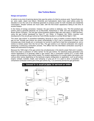
  • 1. Gas Turbine Basics Design and operation A turbine is any kind of spinning device that uses the action of a fluid to produce work. Typical fluids are: air, wind, water, steam and helium. Windmills and hydroelectric dams have used turbine action for decades to turn the core of an electrical generator to produce power for both industrial and residential consumption. Simpler turbines are much older, with the first known appearance dating to the time of ancient Greece. In the history of energy conversion, however, the gas turbine is relatively, new. The first practical gas turbine used to generate electricity ran at Neuchatel, Switzerland in 1939, and was developed by the Brown Boveri Company. The first gas turbine-powered airplane flight also took place in 1939 Germany, using the gas turbine developed by Hans P. von Ohain. In England, the 1930’s invention and development of the aircraft gas turbine by Frank Whittle resulted in a similar British flight in 1941. The name “gas turbine” is somewhat misleading, because to many it implies a turbine engine that uses gas its fuel. Actually gas turbine (as shown schematically in Fig.1) has a compressor to draw in and compress gas (most usually air); a combustor (or burner) to add fuel to heat the compressed air; and a turbine to extract power from the hot air flow. The gas turbine is an internal combustion (IC) engine employing a continuous combustion process. This differs from the intermittent combustion occurring in diesel and automotive ID engines. Because the 1939 origin of the gas turbine lies simultaneously in the electric power field and in aviation, there have been a profusion of “other names” for the gas turbine. For electrical power generation and marine applications it is generally called a gas turbine, also a combustion turbine (CT), a turbo shaft engine, and sometimes a gas turbine engine. For aviation applications it is usually called a jet engine, and various other names depending on the particular engine configuration or application, such as jet turbine engine; turbojet; turbofan; fanjet; and turboprop or prop jet (if it is used to drive a propeller). The compressor-combustor turbine part of the gas turbine (Fig. 1) is commonly termed the gas generator.
  • 2. Gas turbine usage In an aircraft gas turbine the output of the turbine is used to turn the compressor (which may also have an associated fan or propeller). The hot air flow leaving the turbine is then accelerated into the atmosphere through an exhaust nozzle (Fig. 1a) to provide thrust or propulsion power. A typical jet engine is shown in Figure 2. Such engines can range from about 100 pounds of thrust (lbst). to as high as 100,000 lbst. with weights ranging from about 30 lbs. to 20,000 lbs. The smallest jets are used for devices such as the cruise missile, the largest for future generations of commercial aircraft. The jet engine of Figure 2 is a turbofan engine, with a large diameter compressor mounted fan. Thrust is generated both by air passing through the fan (bypass air) and through the gas generator itself. With a large frontal area, the turbofan generates peak thrust at low (takeoff) speeds making it most suitable for commercial aircraft. A turbojet does not have a fan and generates all of its thrust from air that passes through the gas generator. Turbojets have smaller frontal areas and generate peak thrusts at high speeds, making them most suitable for fighter aircraft. In non-aviation gas turbines, part of the turbine power is used to drive the compressor. The remainder, the “useful power”, is used as output shaft power to turn an energy conversion device (fig. 1b) such as an electrical generator or a ship’s propeller. A typical land-based gas turbine is shown in Figure 3. Such units can range in power output from 0.05 MW to as high as 240 MW. The unit shown in figure 3 is an aeroderivative gas turbines i.e., a lighter weight unit derived from an aircraft jet engine. Heavier weight units designed specifically for land use are called industrial or frame machines. Although aeroderivative gas turbines are being increasingly used for baseload electrical power generation, they are most frequently used to drive compressors for natural gas pipelines, power ships and provide peaking and intermittent power for electric utility applications. Peaking power supplements a utility’s normal steam turbine or hydroelectric power output during high demand periods – such as the summer demand for air-conditioning in many major cities.
  • 3. Some of the principal advantages of the gas turbine are: It is capable of producing large amounts of useful power for a relatively small size and weight. Since motion of all its major components involves pure rotation (i.e., no reciprocating motion as in a piston engine), its mechanical life is long and the corresponding maintenance cost is low. Although the gas turbine must be started by some external means (a small external motor or other source, such as another gas turbine), it can be brought up to full-load (peak output) conditions in minutes as contrasted to a steam turbine plant whose start-up time is measured in hours. A wide variety of fuels can be utilised. Natural gas is commonly used in land based gas turbines while light distillate (kerosene-like) oils power aircraft gas turbines. Diesel oil or specially treated residual oils can also be used, as well as combustible gases derived from blast furnaces, refineries and the gasification of solid fuels such as coal, wood chips and bagasse. The usual working fluid is atmospheric air. As a basic power supply, the gas turbine requires no coolant (e.g., water). In the past, one of the major disadvantages of the gas turbine was its lower efficiency (hence higher fuel usage) when compared to other IC engines and to steam turbine power plants. However, during the last 50 years, continuous engineering development work has pushed the thermal efficiency (18 per cent for the 1939 Neuchatel gas turbine) to present levels of about 40 per cent for simple cycle operation, and about 55 per cent for combined cycle operation. Even more fuel-efficient gas turbines are in the planning stages, with simple cycle efficiencies predicted as high as 45-47 per cent and combined cycle machines in the 60 per cent range. These projected values are significantly higher than other prime movers, such as steam power plants. Gas turbines cycles A cycle describes what happens to air as it passes into, through, and out of the gas turbine. The cycle usually describes the relationship between the space occupied by the air in the system (called volume, V) and the pressure (P) it is under. The Brayaton cycle (1876), shown in graphic form in Figure 4a as a pressure volume diagram, is a representation of the properties of a fixed amount of air as it passes through a gas turbine in operation. These same points are also shown in the engine schematic in Figure 4b. Air is compressed from point 1 to point 2. This increases the pressure as the volume of space occupied by the air is reduced.
  • 4. The air is then heated at constant pressure from 2 to 3 in Figure 4. This heat is added by injecting fuel into the combustor and igniting it on a continuous basis. The hot compressed air at point 3 is then allowed to expand (from point 3 to 4) reducing the pressure and temperature and increasing its volume. In the engine in Figure 4b, this represents flow through the turbine to point 3’ and then flow through the power turbine to point 4 to turn a shaft or a ship’s propeller. In Figure 1a, the flow from point 3’ to 4 is through the exit nozzle to produce thrust. The “useful work” in figure 4a is indicated by the curve 3’ to 4. This is the energy available to cause output shaft power for a land-based gas turbine, or thrust for a jet aircraft. The Brayton cycle is completed in Figure 4 by a process in which the volume of the air is decreased (temperature decrease) as heat is absorbed into the atmosphere. Most gas turbine operate in an open cycle mode where, for instance, air is taken in from the atmosphere (point1 in Figs. 4a and 4b) and discharged back into the atmosphere (point 4), with the hot air being cooled naturally after it exits the engine. In a closed cycle gas turbine facility the working fluid (air or other gas) is continuously recycled by cooling the exhaust air (point 4) through a heat exchanger (shown schematically in Fig. 5) and directing. It back to the compressor inlet (point 1). Because of its confined, fixed amount of gas, the closed cycle gas turbine is not an internal combustion engine. In the closed cycle system, combustion cannot be sustained and the normal combustor is replaced with a second heat exchanger to heat the compressed air before it enters the turbine. The heat is supplied by an external source such as a nuclear reactor, the fludised bed of a coal combustion process, or some other heat source. Closed cycle systems using gas turbines have been proposed for missions to Mars and other long-term space applications. A gas turbine that is configured and operated to closely follow the Brayton cycle (Fig. 4) is called a simple cycle gas turbine. Most aircraft gas turbines operate in a simple configuration since attention must be paid to engine weight and frontal area. However, in land or marine applications, additional equipment can be added to the simple cycle gas turbine, leading to increases in efficiency and / or the output of a unit. Three such modifications are regeneration, intercooling and reheating. Regeneration involves the installation of a heat exchanger (recuperator) through which the turbine exhaust gases (point 4 in Fig. 4b) pass. The compressed air (point 2 in Fig. 4b) is then heated in the exhaust gas heat exchanger, before the flow enters the combustor (Fig. 6a). If the regeneration is well designed (i.e., the heat exchanger effectiveness is high and the pressure drops are small) the efficiency will be increased over the simple cycle value. However, the relatively high cost of such a regenerator must also be taken into account. Intercooling also involves the use of a heat exchanger. An intercooler is a heat exchanger. An intercooler is a heat exchanger that cools compressor gas during the compression process. For instance, if the compressor consists of a high and a low pressure unit, the intercooler could be mounted between them to cool the flow and decrease the work necessary for compression in the high pressure compressor
  • 5. (Fig. 6b). The cooling fluid could be atmospheric air or water (e.g., sea water in the case of a marine gas turbine). It can be shown that the output of a gas turbine is increased with a well-designed intercooler. Reheating occurs in the turbine and is a way to increase turbine work without changing compressor work or melting the materials from which the turbine is constructed. If a gas turbine has a high pressure and a low pressure turbine at the back end of the machine, a reheater (usually another combustor) can be used to “reheat” the flow between the two turbines (Fig. 6c.)This can increase efficiency by 1-3 per cent. Reheat in a jet engine is accomplished by adding an afterburner at the turbine exhaust, thereby increasing thrust, at the expense of a greatly increased fuel consumption rate. A combined cycle gas turbine power plant, frequently identified by the abbreviation CCGT, is essentially an electrical power plant in which a gas turbine and a steam turbine are used in combination to achieve greater efficiency than would be possible independently. The gas turbine drives an electrical generator. The gas turbine exhaust is then used to produce steam in a heat exchanger (called a heat recovery steam generator) to supply a steam turbine whose output provides the means to generate more electricity. If the steam is used for heat (e.g., heating buildings), the unit would be called a cogeneration plant or a CHP (combined heat and power) plant. Fig. 7 is a simplified representation of a CCGT and shows it to be two heat engines coupled in series. The “upper” engine is the gas turbine. It expels heat as the input to the “lower” engine (the steam turbine). The steam turbine then rejects heat by means of a steam condenser. Actual efficiency values as high as 52-58 per cent have been attained with CCGT units during the last few years. These units are particularly popular for gas turbine power plants constructed in developing countries.
  • 6. Gas turbine components A greater understanding of the gas turbine and its operation can be gained by considering its three major components (Fig. 1, Fig. 2 and Fig. 3): the compressor, the combustor and the turbine. The features and characteristics will be touched on here only briefly. Compressors and turbines: The compressor components are connected to the turbine by a shaft in order to allow the turbine to turn the compressor. A single shaft gas turbine (Figs. 1a and 1b) has only one shaft connecting the compressor and turbine components. A twinspool gas turbine (Figs. 6b and 6c) has two concentric shafts, a longer one connecting a low pressure compressor to a low pressure turbine (the low spool) which rotates inside a shorter, larger diameter shaft. The shorter, larger diameter shaft connects the high pressure turbine with the higher pressure compressor (the high spool) which rotates at higher speeds than the low spool. A triple-spool engine would have a third, intermediate pressure compressor turbine spool.
  • 7. Gas turbine compressors are either centrifugal or axial, or can be combination of both. Centrifugal compressors (with compressed air output around the outer perimeter of the machine) are robust, generally cost less and are limited to pressure ratios of 6 or 7 to 1. They are found in early gas turbines or in modern, smaller gas turbines. The more efficient, higher capacity axial flow compressors (with compressor air output directed along the centre line of the machine) are used in most gas turbines (e.g., Fig. 2 and Fig. 3). An axial compressor is made up of a relatively large number of stages, each stage, consisting of a row of rotating blades (air foils) and a row of stationary blades (stators), arranged so that the air is compressed as it passes through each stage. Turbines are generally easier to design and operate then compressors, since the hot air flow is expanding rather than being compressed. Axial flow turbines (e.g., Fig. 2 and Fig. 3) will require fewer stages than an axial compressor. There are some smaller gas turbines that utilise centrifugal turbines (radial inflow), but most utilise axial turbines. Turbines design and manufacture is complicated by the need to extend turbine component life in the hot air flow. The problem of ensuring durability is especially critical in the first turbine stage where temperatures are highest. Special materials and elaborate cooling schemes must be used to allow turbine airfoils that melt at 982-1,038o C to survive in air flows with temperatures as high as 1,649o C. Combustors: A successful combustor design must satisfy many requirements and has been a challenge from the earliest gas turbines of Whittle and von Ohain. The relative importance of each requirement varies with the application of the gas turbine, and of course, some requirements are conflicting, requiring design compromises to be made. Most design requirements reflect concerns over engine costs, efficiency, and the environment. The basic design requirements can be classified as follows: High combustion efficiency at all operating conditions. Low levels of unburnt hydrocarbons and carbon monoxide, low oxides of nitrogen at high power and no visible smoke. (Minimised pollutants and emissions) Low pressure drop. Three to 4 per cent is common. Combustion must be stable under all operating conditions. Consistently reliable ignition must be attained at very low temperatures, and at high altitudes (for aircraft). Smooth combustion, with no pulsations or rough burning. A low temperature variation for good turbine life requirements. Useful life (thousands of hours), particularly for industrial use.
  • 8. Multi-fuel use. Characteristically natural gas and diesel fuel are used for industrial applications and kerosene for aircraft. Length and diameter compatible with engine envelope (outside dimensions). Designed for minimum cost, repair and maintenance. Minimum weight (for aircraft applications). A combustor consists of at least three basic parts: a flame tube and a fuel injection system. The casing must withstand the cycle pressures and may be a part of the structure of the gas turbine. It encloses a relatively thin-walled flame tube within which combustion takes place, and a fuel injection system. Compared to other prime movers (such as diesel and reciprocating automobile engines), gas turbines are considered to produce very low levels of combustion pollution. The gas turbine emissions of major concern are unburnt hydrocarbons, carbon monoxide, oxides of nitrogen (NOx) and smoke. While the contribution of jet aircraft to atmospheric pollution is less then 1 per cent, jet aircraft emissions injected directly into the upper troposphere have doubled between the latitudes of 40 to 60 degrees north, increasing ozone by about 20 per cent. In the stratosphere, where supersonic aircraft fly, NOx will deplete ozone. Both effects are harmful so further NOx reduction in gas turbine operation is a challenge for the 21st century. Lee S. Langston and George Opdyke, Jr. Reference book: Power Line, May 2005