SlideShare uma empresa Scribd logo
1 de 36
Baixar para ler offline
SRCEM Database Management System Part 1 2017
Compiled By : Ms. Nandini Sharma Page 1
DATABASE - A database is an organized collection of data.
 It is the collection of schemas, tables, queries, reports, views, and other objects.
 The data are typically organized to model aspects of reality in a way that
supports processes requiring information, such as modeling the availability of rooms in
hotels in a way that supports finding a hotel with vacancies.
DATABASE MANAGEMENT SYSTEM
A database management system (DBMS) is system software for creating and managing
databases. The DBMS provides users and programmers with a systematic way to create, retrieve,
update and manage data.
 A DBMS makes it possible for end users to create, read, update and delete data in a
database. The DBMS essentially serves as an interface between the database and end
users or application programs, ensuring that data is consistently organized and remains
easily accessible.
Below is the example how the data is stored in the database tables logically.
COMPONENTS OF A DATABASE INCLUDES
 User: - Users are the one who really uses the database. Users can be administrator,
developer or the end users.
 Data or Database: - As we discussed already, data is one of the important factor of
database. A very huge amount of data will be stored in the database and it forms the main
source for all other components to interact with each other. There are two types of data.
One is user data. It contains the data which is responsible for the database, i.e.; based on
the requirement, the data will be stored in the various tables of the database in the form of
rows and columns. Another data is Metadata. It is known as ‘data about data’, i.e.; it
stores the information like how many tables, their names, how many columns and their
names, primary keys, foreign keys etc. basically these metadata will have information
about each tables and their constraints in the database.
SRCEM Database Management System Part 1 2017
Compiled By : Ms. Nandini Sharma Page 2
 DBMS: - This is the software helps the user to interact with the database. It allows the
users to insert, delete, update or retrieve the data. All these operations are handled by
query languages like MySQL, Oracle etc.
 Database Application: - It the application program which helps the users to interact with
the database by means of query languages. Database application will not have any idea
about the underlying DBMS.
At very high level, a database is considered as shown in below diagram. Let us see them in detail below.
 Applications: - It can be considered as a user friendly web page where the user enters the
requests. Here he simply enters the details that he needs and presses buttons to get the data.
 End User: - They are the realusers of the database. They can be developers, designers,
administrator or the actual users of the database.
 DDL: - Data Definition Language (DDL) is a query fired to create database,schema,tables,
mappings etc in the database. These are the commands used to create the objects like tables,
indexes in the database for the first time. In other words, they create structure of the database.
 DDL Compiler: - This part of database is responsible for processing the DDL commands. That
means these compiler actually breaks down the command into machine understandable codes. It
is also responsible for storing the metadata information like table name, space used by it, number
of columns in it, mapping information etc.
 DML Compiler: - When the user inserts, deletes, updates or retrieves the record from the
database,he will be sending request which he understands by pressing some buttons. But for the
database to work/understand the request, it should be broken down to object code. This is done by
this compiler. One can imagine this as when a person is asked some question, how this is broken
down into waves to reach the brain!
 Query Optimizer: - When user fires some request, he is least bothered how it will be fired on the
database. He is not all aware of database or its way of performance. But whatever be the request,
it should be efficient enough to fetch,insert, update or delete the data from the database. The
query optimizer decides the best way to execute the user request which is received from the DML
compiler. It is similar to selecting the best nerve to carry the waves to brain!
SRCEM Database Management System Part 1 2017
Compiled By : Ms. Nandini Sharma Page 3
 Stored Data Manager: - This is also known as Database Control System. It is one the main
central system of the database. It is responsible for various tasks
o It converts the requests received from query optimizer to machine understandable form.
It makes actualrequest inside the database. It is like fetching the exact part of the brain to
answer.
o It helps to maintain consistency and integrity by applying the constraints. That means, it
does not allow inserting / updating / deleting any data if it has child entry. Similarly it
does not allow entering any duplicate value into database tables.
o It controls concurrent access. If there is multiple users accessing the database at the same
time, it makes sure, all of them see correct data. It guarantees that there is no data loss or
data mismatch happens between the transactions of multiple users.
o It helps to backup the database and recover data whenever required. Since it is a huge
database and when there is any unexpected exploit of transaction, and reverting the
changes are not easy. It maintains the backup of all data,so that it can be recovered.
 Data Files: - It has the realdata stored in it. It can be stored as magnetic tapes,magnetic disks or
optical disks.
 Compiled DML: - Some of the processed DML statements (insert, update, delete) are stored in it
so that if there is similar requests,it will be re-used.
 Data Dictionary: - It contains all the information about the database. As the name suggests, it is
the dictionary of all the data items. It contains description of all the tables, view, materialized
views, constraints, indexes, triggers etc.
SRCEM Database Management System Part 1 2017
Compiled By : Ms. Nandini Sharma Page 4
ADVANTAGES OF DBMS
DBMS is developed to cover the drawbacks of the traditional file system.
1. Data Mapping and Access: - DBMS defines the way to map any two related tables by means of
primary key –foreign key relationship. Primary key is the column in the table which responsible
for uniquely identifying each record in the table. Foreign key is the column in the table which is a
primary key in other table and with which the entries in the current table are related to other table.
For example, in the new database system,we can Student and Student_Report table as follows.
STUDENT_ID is the unique using which we can identify each student and hence it forms a primary key
in STUDENT table. Similarly, REPORT_ID is the primary key in the STUDENT_REPORT table.
STUDENT_ID in the STUDENT_REPORT table is the foreign key. It links STUDENT and
STUDENT_REPORT tables.
Because of such mapping, it becomes each for the programmer to search for related tables, join them, and
fire the query as per the requirement. This reduces the time consumed while searching and mapping these
tables. Even when there is large amount of data, the time consumed to retrieve, insert, update or delete is
very less. Hence there is no data isolation in the system.
Note: Mapping of tables is usually done when they are created.
2. Data Redundancy: - By the introduction of primary key in the table, data redundancy problem is
reduced to great extent. As we saw,primary key is the unique column for each record, when there
is a re-entry of same record,it does not allow saving such records.
DBMS has strong designing techniques like normalization which makes sure the same copy of data is not
stored in same table or in multiple tables. It makes sure all the informations are stored only once in the
SRCEM Database Management System Part 1 2017
Compiled By : Ms. Nandini Sharma Page 5
database tables.We can see the difference in the way data is being stored in the file and database system.
Primary key, foreign keys are defined; unnecessary columns are removed from the STUDENT_REPORT
table in the database system. These are missing in the file processing system.
3. Data Independence and Consistency: - DBMS defines a standard to represent the data in the
form of rows and columns. It also stores the information about the tables, columns, keys, storage
space,used space,available space etc separately from the logical data. Hence they totally
independent of the way they are stored and the data being stored. Any changes to the physical
storage (like disks, tapes etc) or structure, does not harm the data being stored. Since DBMS
defines each columns and rows at the beginning itself and controls the way data being entered,
there is no affect on the programs or any other tables or data. Hence the consistency of the data
also maintained.
If there is a change in the address of any student, we just have to update it in the Student table. There is no
other place his information is being stored. Hence it maintains the consistent data in the database.
Suppose there is a new column addition to STUDENT table, say DOB. This will change the metadata to
reflect additional column in the table structure. It will hardly affect the application unless until there is a
new requirement to have transaction with DOB. Hence data independence is also assured in the database.
4. Security: - DBMS allows different levels of access to different users based on their roles. In the
school database,individual students will have access to their data alone, while their teachers will
have access to all the students whom they are teaching and for the subjects that they are teaching.
Class teacher will be able to see the reports of all the students in that class, but not other classes.
Similarly, in a banking system, individual account holder will have Read-Only access to their account.
While accountant can update, individual account details for each of their transaction.
All these levels of security and access are not allowed in file system.
5. Integrity: - DBMS allows having restrictions on individual columns. It would be defined while
designing the table itself. If we want to enter salary of an employee within the range 10000 to
40000, we can impose this while designing the table by using CHECK constraint. When salary is
entered, it will automatically check for the range specified.
CREATE TABLE EMPLOYEE ……….. CONSTRAINT chk_salary CHECK (salary>10000 AND
salary <40000)
6. Atomicity: - DBMS makes sure either the transaction is fully complete or it is rolled back to the
previous committed state. It does not allow the system to be in a partially committed state. In our
example above, DBMS commits marks change transaction before calculating the total. If there is
any crash or shutdown of the system, before committing the marks, then updated marks will be
rolled back to the original marks. Hence it makes sure atomicity of the transaction is achieved.
7. Concurrent Access: - DBMS provide access to multiple users to access the database at the same
time. It has its own mechanism to have concurrency accesses and hence avoid any incorrect data
in the system.
SRCEM Database Management System Part 1 2017
Compiled By : Ms. Nandini Sharma Page 6
DISADVANTAGES OF DBMS
1. It is bit complex. Since it supports multiple functionality to give the user the best, the underlying
software has become complex. The designers and developers should have thorough knowledge
about the software to get the most out of it.
2. Because of its complexity and functionality, it uses large amount of memory. It also needs large
memory to run efficiently.
3. DBMS system works on the centralized system, i.e.; all the users from all over the world access
this database. Hence any failure of the DBMS, will impact all the users.
4. DBMS is generalized software,i.e.; it is written work on the entire systems rather specific one.
Hence some of the application will run slow.
TYPES OF DATABASE LANGUAGES
1. Data Definition of Language (DDL), which deals with database schemas and description,
of how the data should reside in the database.
 CREATE – to create database and its object like (table, index, views, store,
function)
 ALTER – alters the structure of the existing database.
SRCEM Database Management System Part 1 2017
Compiled By : Ms. Nandini Sharma Page 7
 DROP – to delete objects from the database.
 TRUNCATE – remove all records from a table, including all spaces allocated for
the records are removed.
 COMMENT – add comment to the data dictionary.
 RENAME- renames an object.
2. Data Manipulation Language (DML) which deals with data manipulation, and includes
most common SQL statements such SELECT,INSERT,UPDATE,DELETE etc, and it is
used to store , modify, retrieve, delete and update data in database.
 SELECT- retrieve data from the database.
 INSERT – insert data into a table.
 UPDATE – updates existing data within a table.
 DELETE – Delete all records form a database table.
 MERGE – UPSERT operation (insert or update).
 CALL- call a PL/SQL or Java subprogram.
 EXPLAIN PLAN – interpretation of the data access path.
 LOCK TABLE- concurrency control.
3. Data Control Languages (DCL) which includes commands such as GRANT, and mostly
concerned with rights, permissions and other controls of the database system.
 GRANT – allow users access privileges to database.
 REVOKE – withdraw user’s access privileges given by using the GRANT
command.
4. Tool Command Language – Transactional Control Language which deals with
transaction within a database.
 COMMIT – commits a transaction.
 ROLLBACK – rollback a transaction in a case of any errors.
 SAVEPOINT – to rollback transaction making point within a group.
 SET TRANSACTIONS – specify characteristics for the transaction.
DATA MODELS
SRCEM Database Management System Part 1 2017
Compiled By : Ms. Nandini Sharma Page 8
E-R Diagram
ER-Diagram is a visual representation of data that describes how data is related to each other.
SRCEM Database Management System Part 1 2017
Compiled By : Ms. Nandini Sharma Page 9
Symbols and Notations
SRCEM Database Management System Part 1 2017
Compiled By : Ms. Nandini Sharma Page 10
Components of E-R Diagram
The E-R diagram has three main components.
1) Entity
An Entity can be any object, place, person or class. In E-R Diagram, an entity is represented
using rectangles. Consider an example of an Organization. Employee, Manager, Department,
Product and many more can be taken as entities from an Organization.
Weak Entity
Weak entity is an entity that depends on another entity. Weak entity doen't have key attribute of
their own. Double rectangle represents weak entity.
SRCEM Database Management System Part 1 2017
Compiled By : Ms. Nandini Sharma Page 11
2) Attribute
An Attribute describes a property or characteristic of an entity. For example, Name, Age,
Address etc can be attributes of a Student. An attribute is represented using eclipse.
Key Attribute
Key attribute represents the main characteristic of an Entity. It is used to represent Primary key.
Ellipse with underlying lines represent Key Attribute.
Composite Attribute
An attribute can also have their own attributes. These attributes are known
as Composite attribute.
SRCEM Database Management System Part 1 2017
Compiled By : Ms. Nandini Sharma Page 12
3) Relationship
A Relationship describes relations between entities. Relationship is represented using diamonds.
There are three types of relationship that exist between Entities.
 Binary Relationship
 Recursive Relationship
 Ternary Relationship
SRCEM Database Management System Part 1 2017
Compiled By : Ms. Nandini Sharma Page 13
Binary Relationship
Binary Relationship means relation between two Entities. This is further divided into three types.
1. One to One : This type of relationship is rarely seen in real world.
The above example describes that one student can enroll only for one course and a course
will also have only one Student. This is not what you will usually see in relationship.
2. One to Many : It reflects business rule that one entity is associated with many number of
same entity. The example for this relation might sound a little weird, but this menas that one
student can enroll to many courses, but one course will have one Student.
SRCEM Database Management System Part 1 2017
Compiled By : Ms. Nandini Sharma Page 14
The arrows in the diagram describes that one student can enroll for only one course.
3. Many to One : It reflects business rule that many entities can be associated with just one
entity. For example, Student enrolls for only one Course but a Course can have many
Students.
4. Many to Many :
SRCEM Database Management System Part 1 2017
Compiled By : Ms. Nandini Sharma Page 15
The above diagram represents that many students can enroll for more than one courses.
Recursive Relationship
When an Entity is related with itself it is known as Recursive Relationship.
Ternary Relationship
Relationship of degree three is called Ternary relationship.
SRCEM Database Management System Part 1 2017
Compiled By : Ms. Nandini Sharma Page 16
ER Model is represented by means of an ER diagram. Any object, for example, entities,
attributes of an entity, relationship sets, and attributes of relationship sets, can be represented
with the help of an ER diagram.
Entity
Entities are represented by means of rectangles. Rectangles are named with the entity set they
represent.
Attributes
Attributes are the properties of entities. Attributes are represented by means of ellipses. Every
ellipse represents one attribute and is directly connected to its entity (rectangle).
If the attributes are composite, they are further divided in a tree like structure. Every node is
then connected to its attribute. That is, composite attributes are represented by ellipses that are
connected with an ellipse.
SRCEM Database Management System Part 1 2017
Compiled By : Ms. Nandini Sharma Page 17
Multivalued attributes are depicted by double ellipse.
Derived attributes are depicted by dashed ellipse.
Relationship
Relationships are represented by diamond-shaped box. Name of the relationship is written
inside the diamond-box. All the entities (rectangles) participating in a relationship, are
connected to it by a line.
Binary Relationship and Cardinality
A relationship where two entities are participating is called a binary relationship. Cardinality
is the number of instance of an entity from a relation that can be associated with the relation.
 One-to-one − When only one instance of an entity is associated with the relationship, it
is marked as '1:1'. The following image reflects that only one instance of each entity
should be associated with the relationship. It depicts one-to-one relationship.
SRCEM Database Management System Part 1 2017
Compiled By : Ms. Nandini Sharma Page 18
 One-to-many − When more than one instance of an entity is associated with a
relationship, it is marked as '1:N'. The following image reflects that only one instance of
entity on the left and more than one instance of an entity on the right can be associated
with the relationship. It depicts one-to-many relationship.
 Many-to-one − When more than one instance of entity is associated with the
relationship, it is marked as 'N:1'. The following image reflects that more than one
instance of an entity on the left and only one instance of an entity on the right can be
associated with the relationship. It depicts many-to-one relationship.
SRCEM Database Management System Part 1 2017
Compiled By : Ms. Nandini Sharma Page 19
 Many-to-many − The following image reflects that more than one instance of an entity
on the left and more than one instance of an entity on the right can be associated with the
relationship. It depicts many-to-many relationship.
Participation Constraints
 Total Participation − Each entity is involved in the relationship. Total participation is
represented by double lines.
 Partial participation − Not all entities are involved in the relationship. Partial
participation is represented by single lines.
The ER Model has the power of expressing database entities in a conceptual hierarchical manner.
As the hierarchy goes up, it generalizes the view of entities, and as we go deep in the hierarchy,
it gives us the detail of every entity included.
Going up in this structure is called generalization, where entities are clubbed together to
represent a more generalized view. For example, a particular student named Mira can be
generalized along with all the students. The entity shall be a student, and further, the student is a
person. The reverse is called specialization where a person is a student, and that student is Mira.
Generalization
As mentioned above, the process of generalizing entities, where the generalized entities contain
the properties of all the generalized entities, is called generalization. In generalization, a number
SRCEM Database Management System Part 1 2017
Compiled By : Ms. Nandini Sharma Page 20
of entities are brought together into one generalized entity based on their similar characteristics.
For example, pigeon, house sparrow, crow and dove can all be generalized as Birds.
Specialization
Specialization is the opposite of generalization. In specialization, a group of entities is divided
into sub-groups based on their characteristics. Take a group ‘Person’ for example. A person has
name, date of birth, gender, etc. These properties are common in all persons, human beings. But
in a company, persons can be identified as employee, employer, customer, or vendor, based on
what role they play in the company.
Similarly, in a school database, persons can be specialized as teacher, student, or a staff, based
on what role they play in school as entities.
Inheritance
We use all the above features of ER-Model in order to create classes of objects in object-oriented
programming. The details of entities are generally hidden from the user; this process known
as abstraction.
Inheritance is an important feature of Generalization and Specialization. It allows lower-level
entities to inherit the attributes of higher-level entities.
SRCEM Database Management System Part 1 2017
Compiled By : Ms. Nandini Sharma Page 21
For example, the attributes of a Person class such as name, age, and gender can be inherited by
lower-level entities such as Student or Teacher.
OBJECT ORIENTED DATA MODEL
An object database (also object-oriented database management system, OODBMS) is a database
management system in which information is represented in the form of objects as used in object-
oriented programming. Object databases are different from relational databases which are table-
oriented. Object-relational databases are a hybrid of both approaches.
SRCEM Database Management System Part 1 2017
Compiled By : Ms. Nandini Sharma Page 22
Object-oriented database management systems (OODBMSs) combines database capabilities
with object-oriented programming language capabilities. OODBMSs allow object-oriented
programmers to develop the product, store them as objects, and replicate or modify existing
objects to make new objects within the OODBMS. Because the database is integrated with the
programming language, the programmer can maintain consistency within one environment, in
that both the OODBMS and the programming language will use the same model of
representation. Relational DBMS projects, by way of contrast, maintain a clearer division
between the database model and the application.
As the usage of web-based technology increases with the implementation of Intranets and
extranets, companies have a vested interest in OODBMSs to display their complex data. Using a
DBMS that has been specifically designed to store data as objects gives an advantage to those
companies that are geared towards multimedia presentation or organizations that
utilize computer-aided design (CAD).
Some object-oriented databases are designed to work well with object-oriented programming
languages such as Delphi, Ruby, Python, Perl, Java, C#, Visual Basic .NET, C++, Objective-
C and Smalltalk; others such as JADE have their own programming languages. OODBMSs use
exactly the same model as object-oriented programming languages.
Relational Data Model
Relational data model is the primary data model, which is used widely around the world for data
storage and processing. This model is simple and it has all the properties and capabilities
required to process data with storage efficiency.
Concepts
Tables − In relational data model, relations are saved in the format of Tables. This format stores
the relation among entities. A table has rows and columns, where rows represents records and
columns represent the attributes.
Tuple − A single row of a table, which contains a single record for that relation is called a tuple.
Relation instance − A finite set of tuples in the relational database system represents relation
instance. Relation instances do not have duplicate tuples.
Relation schema − A relation schema describes the relation name (table name), attributes, and
their names.
Relation key − Each row has one or more attributes, known as relation key, which can identify
the row in the relation (table) uniquely.
SRCEM Database Management System Part 1 2017
Compiled By : Ms. Nandini Sharma Page 23
Attribute domain − Every attribute has some pre-defined value scope, known as attribute
domain.
Constraints
Every relation has some conditions that must hold for it to be a valid relation. These conditions
are called Relational Integrity Constraints. There are three main integrity constraints −
 Key constraints
 Domain constraints
 Referential integrity constraints
Key Constraints
There must be at least one minimal subset of attributes in the relation, which can identify a tuple
uniquely. This minimal subset of attributes is called key for that relation. If there are more than
one such minimal subsets, these are called candidate keys.
Key constraints force that −
 in a relation with a key attribute, no two tuples can have identical values for key
attributes.
 a key attribute cannot have NULL values.
Key constraints are also referred to as Entity Constraints.
Domain Constraints
Attributes have specific values in real-world scenario. For example, age can only be a positive
integer. The same constraints have been tried to employ on the attributes of a relation. Every
attribute is bound to have a specific range of values. For example, age cannot be less than zero
and telephone numbers cannot contain a digit outside 0-9.
Referential integrity Constraints
Referential integrity constraints work on the concept of Foreign Keys. A foreign key is a key
attribute of a relation that can be referred in other relation.
Referential integrity constraint states that if a relation refers to a key attribute of a different or
same relation, then that key element must exist.
SRCEM Database Management System Part 1 2017
Compiled By : Ms. Nandini Sharma Page 24
In this model, data is organised in two-dimesional tables called relations. The tables or relation
are related to each other.
Hierarchical Model
In this model each entity has only one parent but can have several children. At the top of
hierarchy there is only one entity which is called Root.
SRCEM Database Management System Part 1 2017
Compiled By : Ms. Nandini Sharma Page 25
Network Model
In the network model, entities are organized in a graph, in which some entities can be accessed
through several path.
DBA Responsibilities
 Installation, configuration and upgrading of Microsoft SQL Server/MySQL/Oracle server
software and related products.
 Evaluate MSSQL/MySQL/Oracle features and MSSQL/MySQL/Oracle related products.
 Establish and maintain sound backup and recovery policies and procedures.
 Take care of the Database design and implementation.
 Implement and maintain database security (create and maintain users and roles, assign
privileges).
 Database tuning and performance monitoring.
 Application tuning and performance monitoring.
 Setup and maintain documentation and standards.
 Plan growth and changes (capacity planning).
 Work as part of a team and provide 7×24 supports when required.
 Do general technical trouble shooting and give consultation to development teams.
 Interface with MSSQL/MySQL/Oracle for technical support.
 ITIL Skill set requirement (Problem Management/Incident Management/Chain
Management etc)
SRCEM Database Management System Part 1 2017
Compiled By : Ms. Nandini Sharma Page 26
Types of DBA
1. Administrative DBA – Work on maintaining the server and keeping it running.
Concerned with backups, security, patches, replication, etc. Things that concern the
actual server software.
2. Development DBA – works on building queries, stored procedures, etc. that meet
business needs. This is the equivalent of the programmer. You primarily write T-SQL.
3. Architect – Design schemas. Build tables, FKs, PKs, etc. Work to build a structure that
meets the business needs in general. The design is then used by developers and
development DBAs to implement the actual application.
4. Data Warehouse DBA – Newer role, but responsible for merging data from multiple
sources into a data warehouse. May have to design warehouse, but cleans, standardizes,
and scrubs data before loading. In SQL Server, this DBA would use DTS heavily.
5. OLAP DBA – Builds multi-dimensional cubes for decision support or OLAP systems.
The primary language in SQL Server is MDX, not SQL here
Application DBA- Application DBAs straddle the fence between the DBMS and the application
software and are responsible for ensuring that the application is fully optimized for the database
and vice versa. They usually manage all the application components that interact with the
database and carry out activities such as application installation and patching, application
upgrades, database cloning, building and running data cleanup routines, data load process
management, etc.
Types of keys in DBMS
 Primary Key – A primary is a column or set of columns in a table that uniquely
identifies tuples (rows) in that table.
 Super Key – A super key is a set of one of more columns (attributes) to uniquely identify
rows in a table.
 Candidate Key – A super key with no redundant attribute is known as candidate key
 Alternate Key – Out of all candidate keys, only one gets selected as primary key,
remaining keys are known as alternate or secondary keys.
 Composite Key – A key that consists of more than one attribute to uniquely identify
rows (also known as records & tuples) in a table is called composite key.
 Foreign Key – Foreign keys are the columns of a table that points to the primary key of
another table. They act as a cross-reference between tables.
SRCEM Database Management System Part 1 2017
Compiled By : Ms. Nandini Sharma Page 27
Three levels of database architecture
1. Physical Level
2. Conceptual Level
3. External Level
In the above diagram,
 It shows the architecture of DBMS.
 Mapping is the process of transforming request response between various database levels
of architecture.
 Mapping is not good for small database, because it takes more time.
 In External / Conceptual mapping, DBMS transforms a request on an external schema
against the conceptual schema.
 In Conceptual / Internal mapping, it is necessary to transform the request from the
conceptual to internal levels.
SRCEM Database Management System Part 1 2017
Compiled By : Ms. Nandini Sharma Page 28
1. Physical Level
 Physical level describes the physical storage structure of data in database.
 It is also known as Internal Level.
 This level is very close to physical storage of data.
 At lowest level, it is stored in the form of bits with the physical addresses on the
secondary storage device.
 At highest level, it can be viewed in the form of files.
 The internal schema defines the various stored data types. It uses a physical data model.
2. Conceptual Level
 Conceptual level describes the structure of the whole database for a group of users.
 It is also called as the data model.
 Conceptual schema is a representation of the entire content of the database.
 These schema contains all the information to build relevant external records.
 It hides the internal details of physical storage.
3. External Level
 External level is related to the data which is viewed by individual end users.
 This level includes a no. of user views or external schemas.
 This level is closest to the user.
 External view describes the segment of the database that is required for a particular user
group and hides the rest of the database from that user group.
Client/Server Architecture
In the Oracle client/server architecture, the database application and the database are separated
into two parts: a front-end or client portion, and a back-end or server portion. The client executes
the database application that accesses database information and interacts with a user through the
keyboard, screen, and pointing device such as a mouse. The server executes the Oracle software
and handles the functions required for concurrent, shared data access to an Oracle database.
Although the client application and Oracle can be executed on the same computer, it may be
more efficient and effective when the client portion(s) and server portion are executed by
different computers connected via a network. The following sections discuss possible variants in
the Oracle client/server architecture.
Note: In a distributed database, one server (Oracle) may need to access a database on another
server. In this case, the server requesting the information is a client. "Distributed Databases", for
more information about clients and servers in distributed databases.
SRCEM Database Management System Part 1 2017
Compiled By : Ms. Nandini Sharma Page 29
Distributed Processing
Distributed processing is the use of more than one processor to divide the processing for an
individual task. The following are examples of distributed processing in Oracle database
systems:
 The client and server are located on different computers; these computers are connected
via a network (see Figure 20 - 1, Part A).
 A single computer has more than one processor, and different processors separate the
execution of the client application from Oracle (see Figure 20 - 1, Part B).
SRCEM Database Management System Part 1 2017
Compiled By : Ms. Nandini Sharma Page 30
Figure 20 - 1. The Client/Server Architecture and Distributed Processing
Benefits of the Oracle client/server architecture in a distributed processing environment include
the following:
 Client applications are not responsible for performing any data processing. Client
applications can concentrate on requesting input from users, requesting desired data from
the server, and then analyzing and presenting this data using the display capabilities of
the client workstation or the terminal (for example, using graphics or spreadsheets).
 Client applications can be designed with no dependence on the physical location of the
data. If the data is moved or distributed to other database servers, the application
continues to function with little or no modification.
 Oracle exploits the multitasking and shared-memory facilities of its underlying operating
system. As a result, it delivers the highest possible degree of concurrency, data integrity,
and performance to its client applications.
 Client workstations or terminals can be optimized for the presentation of data (for
example, by providing graphics and mouse support) and the server can be optimized for
the processing and storage of data (for example, by having large amounts of memory and
disk space).
 If necessary, Oracle can be scaled. As your system grows, you can add multiple servers
to distribute the database processing load throughout the network (horizontally scaled).
Alternatively, you can replace Oracle on a less powerful computer, such as a
microcomputer, with Oracle running on a minicomputer or mainframe, to take advantage
of a larger system's performance (vertically scaled). In either case, all data and
applications are maintained with little or no modification, since Oracle is portable
between systems.
 In networked environments, shared data is stored on the servers, rather than on all
computers in the system. This makes it easier and more efficient to manage concurrent
access.
 In networked environments, inexpensive, low-end client workstations can be used to
access the remote data of the server effectively.
 In networked environments, client applications submit database requests to the server
using SQL statements. Once received, the SQL statement is processed by the server, and
the results are returned to the client application. Network traffic is kept to a minimum
because only the requests and the results are shipped over the network.
SRCEM Database Management System Part 1 2017
Compiled By : Ms. Nandini Sharma Page 31
Sequential File Organization
It is one of the simple methods of file organization. Here each file/records are stored one after the
other in a sequential manner. This can be achieved in two ways:
 Records are stored one after the other as they are inserted into the tables. This method is
calledpile file method. When a new record is inserted, it is placed at the end of the file.
In the case of any modification or deletion of record, the record will be searched in the
memory blocks. Once it is found, it will be marked for deleting and new block of record
is entered.
Inserting a new record:
In the diagram above, R1, R2, R3 etc are the records. They contain all the attribute of a row. i.e.;
when we say student record, it will have his id, name, address, course, DOB etc. Similarly R1,
R2, R3 etc can be considered as one full set of attributes.
 In the second method, records are sorted (either ascending or descending) each time they
are inserted into the system. This method is called sorted file method. Sorting of records
may be based on the primary key or on any other columns. Whenever a new record is
inserted, it will be inserted at the end of the file and then it will sort – ascending or
descending based on key value and placed at the correct position. In the case of update, it
SRCEM Database Management System Part 1 2017
Compiled By : Ms. Nandini Sharma Page 32
will update the record and then sort the file to place the updated record in the right place.
Same is the case with delete.
Inserting a new record:
Advantages of Sequential File Organization
 The design is very simple compared other file organization. There is no much effort
involved to store the data.
 When there are large volumes of data, this method is very fast and efficient. This method
is helpful when most of the records have to be accessed like calculating the grade of a
student, generating the salary slips etc where we use all the records for our calculations
 This method is good in case of report generation or statistical calculations.
 These files can be stored in magnetic tapes which are comparatively cheap.
Disadvantages of Sequential File Organization
 Sorted file method always involves the effort for sorting the record. Each time any
insert/update/ delete transaction is performed, file is sorted. Hence identifying the record,
inserting/ updating/ deleting the record, and then sorting them always takes some time
and may make system slow.
SRCEM Database Management System Part 1 2017
Compiled By : Ms. Nandini Sharma Page 33
Indexed Sequential Access Method (ISAM)
This is an advanced sequential file organization method. Here records are stored in order of
primary key in the file. Using the primary key, the records are sorted. For each primary key, an
index value is generated and mapped with the record. This index is nothing but the address of
record in the file.
In this method, if any record has to be retrieved, based on its index value, the data block address
is fetched and the record is retrieved from memory.
Advantages of ISAM
 Since each record has its data block address, searching for a record in larger database is
easy and quick. There is no extra effort to search records. But proper primary key has
to be selected to make ISAM efficient.
 This method gives flexibility of using any column as key field and index will be
generated based on that. In addition to the primary key and its index, we can have
index generated for other fields too. Hence searching becomes more efficient, if there
is search based on columns other than primary key.
SRCEM Database Management System Part 1 2017
Compiled By : Ms. Nandini Sharma Page 34
 It supports range retrieval, partial retrieval of records. Since the index is based on the key
value, we can retrieve the data for the given range of values. In the same way, when a
partial key value is provided, say student names starting with ‘JA’ can also be searched
easily.
Disadvantages of ISAM
 An extra cost to maintain index has to be afforded. i.e.; we need to have extra space in the
disk to store this index value. When there is multiple key-index combinations, the disk
space will also increase.
As the new records are inserted, these files have to be restructured to maintain the sequence.
Similarly, when the record is deleted, the space used by it needs to be released. Else, the
performance of the database will slow down.
Hash/Direct File Organization
In this method of file organization, hash function is used to calculate the address of the block to
store the records. The hash function can be any simple or complex mathematical function. The
hash function is applied on some columns/attributes – either key or non-key columns to get the
block address. Hence each record is stored randomly irrespective of the order they come. Hence
this method is also known as Direct or Random file organization. If the hash function is
generated on key column, then that column is called hash key, and if hash function is generated
on non-key column, then the column is hash column.
When a record has to be retrieved, based on the hash key column, the address is generated and
directly from that address whole record is retrieved. Here no effort to traverse through whole file.
Similarly when a new record has to be inserted, the address is generated by hash key and record
SRCEM Database Management System Part 1 2017
Compiled By : Ms. Nandini Sharma Page 35
is directly inserted. Same is the case with update and delete. There is no effort for searching the
entire file nor sorting the files. Each record will be stored randomly in the memory.
These types of file organizations are useful in online transaction systems, where retrieval or
insertion/updation should be faster.
Advantages of Hash File Organization
 Records need not be sorted after any of the transaction. Hence the effort of sorting is
reduced in this method.
 Since block address is known by hash function, accessing any record is very faster.
Similarly updating or deleting a record is also very quick.
 This method can handle multiple transactions as each record is independent of other. i.e.;
since there is no dependency on storage location for each record, multiple records can be
accessed at the same time.
 It is suitable for online transaction systems like online banking, ticket booking system
etc.
Disadvantages of Hash File Organization
 This method may accidentally delete the data. For example, In Student table, when hash
field is on the STD_NAME column and there are two same names – ‘Antony’, then same
address is generated. In such case, older record will be overwritten by newer. So there
will be data loss. Thus hash columns needs to be selected with utmost care. Also, correct
backup and recovery mechanism has to be established.
SRCEM Database Management System Part 1 2017
Compiled By : Ms. Nandini Sharma Page 36
 Since all the records are randomly stored, they are scattered in the memory. Hence
memory is not efficiently used.
 If we are searching for range of data, then this method is not suitable. Because, each
record will be stored at random address. Hence range search will not give the correct
address range and searching will be inefficient. For example, searching the employees
with salary from 20K to 30K will be efficient.
 Searching for records with exact name or value will be efficient. If the Student name
starting with ‘B’ will not be efficient as it does not give the exact name of the student.
 If there is a search on some columns which is not a hash column, then the search will not
be efficient. This method is efficient only when the search is done on hash column.
Otherwise, it will not be able find the correct address of the data.
 If there is multiple hash columns – say name and phone number of a person, to generate
the address, and if we are searching any record using phone or name alone will not give
correct results.
 If these hash columns are frequently updated, then the data block address is also changed
accordingly. Each update will generate new address. This is also not acceptable.
Hardware and software required for the memory management are costlier in this case. Complex
programs needs to be written to make this method efficient.

Mais conteúdo relacionado

Mais procurados

Transaction management DBMS
Transaction  management DBMSTransaction  management DBMS
Transaction management DBMSMegha Patel
 
Adbms 16 object definition language
Adbms 16 object definition languageAdbms 16 object definition language
Adbms 16 object definition languageVaibhav Khanna
 
Integrity Constraints
Integrity ConstraintsIntegrity Constraints
Integrity Constraintsmadhav bansal
 
Object Oriented Database Management System
Object Oriented Database Management SystemObject Oriented Database Management System
Object Oriented Database Management SystemAjay Jha
 
Introduction & history of dbms
Introduction & history of dbmsIntroduction & history of dbms
Introduction & history of dbmssethu pm
 
Chapter 2 database environment
Chapter 2 database environmentChapter 2 database environment
Chapter 2 database environment>. &lt;
 
Dbms Notes Lecture 9 : Specialization, Generalization and Aggregation
Dbms Notes Lecture 9 : Specialization, Generalization and AggregationDbms Notes Lecture 9 : Specialization, Generalization and Aggregation
Dbms Notes Lecture 9 : Specialization, Generalization and AggregationBIT Durg
 
Database Management System, Lecture-1
Database Management System, Lecture-1Database Management System, Lecture-1
Database Management System, Lecture-1Sonia Mim
 
DATABASE MANAGEMENT SYSTEM
DATABASE MANAGEMENT SYSTEMDATABASE MANAGEMENT SYSTEM
DATABASE MANAGEMENT SYSTEMSonia Pahuja
 
2. Entity Relationship Model in DBMS
2. Entity Relationship Model in DBMS2. Entity Relationship Model in DBMS
2. Entity Relationship Model in DBMSkoolkampus
 

Mais procurados (20)

Transaction management DBMS
Transaction  management DBMSTransaction  management DBMS
Transaction management DBMS
 
Relational model
Relational modelRelational model
Relational model
 
Adbms 16 object definition language
Adbms 16 object definition languageAdbms 16 object definition language
Adbms 16 object definition language
 
Integrity Constraints
Integrity ConstraintsIntegrity Constraints
Integrity Constraints
 
Object oriented databases
Object oriented databasesObject oriented databases
Object oriented databases
 
Acid properties
Acid propertiesAcid properties
Acid properties
 
Object Oriented Database Management System
Object Oriented Database Management SystemObject Oriented Database Management System
Object Oriented Database Management System
 
Introduction & history of dbms
Introduction & history of dbmsIntroduction & history of dbms
Introduction & history of dbms
 
Chapter 2 database environment
Chapter 2 database environmentChapter 2 database environment
Chapter 2 database environment
 
rdbms-notes
rdbms-notesrdbms-notes
rdbms-notes
 
Concurrency control
Concurrency controlConcurrency control
Concurrency control
 
Dbms Notes Lecture 9 : Specialization, Generalization and Aggregation
Dbms Notes Lecture 9 : Specialization, Generalization and AggregationDbms Notes Lecture 9 : Specialization, Generalization and Aggregation
Dbms Notes Lecture 9 : Specialization, Generalization and Aggregation
 
Database Management System, Lecture-1
Database Management System, Lecture-1Database Management System, Lecture-1
Database Management System, Lecture-1
 
DATABASE MANAGEMENT SYSTEM
DATABASE MANAGEMENT SYSTEMDATABASE MANAGEMENT SYSTEM
DATABASE MANAGEMENT SYSTEM
 
View of data DBMS
View of data DBMSView of data DBMS
View of data DBMS
 
Active database
Active databaseActive database
Active database
 
Databases: Normalisation
Databases: NormalisationDatabases: Normalisation
Databases: Normalisation
 
Triggers and active database
Triggers and active databaseTriggers and active database
Triggers and active database
 
Temporal databases
Temporal databasesTemporal databases
Temporal databases
 
2. Entity Relationship Model in DBMS
2. Entity Relationship Model in DBMS2. Entity Relationship Model in DBMS
2. Entity Relationship Model in DBMS
 

Destaque

Bce notes unit 1 be 205
Bce notes unit 1 be 205Bce notes unit 1 be 205
Bce notes unit 1 be 205NANDINI SHARMA
 
Unit 5 animation notes
Unit 5 animation notesUnit 5 animation notes
Unit 5 animation notesNANDINI SHARMA
 
Operating system notes
Operating system notesOperating system notes
Operating system notesSANTOSH RATH
 
3D transformation - Unit 3 Computer grpahics
3D transformation - Unit 3 Computer grpahics3D transformation - Unit 3 Computer grpahics
3D transformation - Unit 3 Computer grpahicsNANDINI SHARMA
 
Unit 4 Multimedia CSE Vth sem
Unit 4 Multimedia CSE Vth semUnit 4 Multimedia CSE Vth sem
Unit 4 Multimedia CSE Vth semNANDINI SHARMA
 
Operating system concepts (notes)
Operating system concepts (notes)Operating system concepts (notes)
Operating system concepts (notes)Sohaib Danish
 
Computer Network notes (handwritten) UNIT 1
Computer Network notes (handwritten) UNIT 1Computer Network notes (handwritten) UNIT 1
Computer Network notes (handwritten) UNIT 1NANDINI SHARMA
 
Notes 2D-Transformation Unit 2 Computer graphics
Notes 2D-Transformation Unit 2 Computer graphicsNotes 2D-Transformation Unit 2 Computer graphics
Notes 2D-Transformation Unit 2 Computer graphicsNANDINI SHARMA
 
3D transformation in computer graphics
3D transformation in computer graphics3D transformation in computer graphics
3D transformation in computer graphicsSHIVANI SONI
 

Destaque (12)

Bce notes unit 1 be 205
Bce notes unit 1 be 205Bce notes unit 1 be 205
Bce notes unit 1 be 205
 
Unit 5 animation notes
Unit 5 animation notesUnit 5 animation notes
Unit 5 animation notes
 
Operating system notes
Operating system notesOperating system notes
Operating system notes
 
3D transformation - Unit 3 Computer grpahics
3D transformation - Unit 3 Computer grpahics3D transformation - Unit 3 Computer grpahics
3D transformation - Unit 3 Computer grpahics
 
Dbms Lecture Notes
Dbms Lecture NotesDbms Lecture Notes
Dbms Lecture Notes
 
Computer Graphics
Computer GraphicsComputer Graphics
Computer Graphics
 
Unit 4 Multimedia CSE Vth sem
Unit 4 Multimedia CSE Vth semUnit 4 Multimedia CSE Vth sem
Unit 4 Multimedia CSE Vth sem
 
Imp notes dbms
Imp notes dbmsImp notes dbms
Imp notes dbms
 
Operating system concepts (notes)
Operating system concepts (notes)Operating system concepts (notes)
Operating system concepts (notes)
 
Computer Network notes (handwritten) UNIT 1
Computer Network notes (handwritten) UNIT 1Computer Network notes (handwritten) UNIT 1
Computer Network notes (handwritten) UNIT 1
 
Notes 2D-Transformation Unit 2 Computer graphics
Notes 2D-Transformation Unit 2 Computer graphicsNotes 2D-Transformation Unit 2 Computer graphics
Notes 2D-Transformation Unit 2 Computer graphics
 
3D transformation in computer graphics
3D transformation in computer graphics3D transformation in computer graphics
3D transformation in computer graphics
 

Semelhante a Database Management System

Database management system by Gursharan singh
Database management system by Gursharan singhDatabase management system by Gursharan singh
Database management system by Gursharan singhGursharan Singh
 
Introduction To Database.ppt
Introduction To Database.pptIntroduction To Database.ppt
Introduction To Database.pptRithikRaj25
 
Database Management System
Database Management SystemDatabase Management System
Database Management SystemNishant Munjal
 
database management system - overview of entire dbms
database management system - overview of entire dbmsdatabase management system - overview of entire dbms
database management system - overview of entire dbmsvikramkagitapu
 
Chap1-Introduction to database systems.ppt
Chap1-Introduction to database systems.pptChap1-Introduction to database systems.ppt
Chap1-Introduction to database systems.pptLisaMalar
 
Database Management System Part-1.pptx
Database Management System Part-1.pptxDatabase Management System Part-1.pptx
Database Management System Part-1.pptxArshveerSinghDhillon
 
Data base management system
Data base management systemData base management system
Data base management systemNavneet Jingar
 
Database management system
Database management systemDatabase management system
Database management systemsonykhan3
 
Detailed overview on Database and database system
Detailed overview on Database and database systemDetailed overview on Database and database system
Detailed overview on Database and database systemsamreenghauri786
 
Database Management Systems (Mcom Ecommerce)
Database Management Systems (Mcom Ecommerce)Database Management Systems (Mcom Ecommerce)
Database Management Systems (Mcom Ecommerce)Rupen Parte
 
Components and Advantages of DBMS
Components and Advantages of DBMSComponents and Advantages of DBMS
Components and Advantages of DBMSShubham Joon
 
Database Management System.docx
Database Management System.docxDatabase Management System.docx
Database Management System.docxantonymwangi31
 
Database and Database Management (DBM): Health Informatics
Database and Database Management (DBM): Health InformaticsDatabase and Database Management (DBM): Health Informatics
Database and Database Management (DBM): Health InformaticsZulfiquer Ahmed Amin
 
Database Systems - introduction
Database Systems - introductionDatabase Systems - introduction
Database Systems - introductionJananath Banuka
 

Semelhante a Database Management System (20)

Dbms quick guide
Dbms quick guideDbms quick guide
Dbms quick guide
 
Database management system by Gursharan singh
Database management system by Gursharan singhDatabase management system by Gursharan singh
Database management system by Gursharan singh
 
Introduction To Database.ppt
Introduction To Database.pptIntroduction To Database.ppt
Introduction To Database.ppt
 
Database Management System
Database Management SystemDatabase Management System
Database Management System
 
database management system - overview of entire dbms
database management system - overview of entire dbmsdatabase management system - overview of entire dbms
database management system - overview of entire dbms
 
Chap1-Introduction to database systems.ppt
Chap1-Introduction to database systems.pptChap1-Introduction to database systems.ppt
Chap1-Introduction to database systems.ppt
 
Introduction DBMS.pptx
Introduction DBMS.pptxIntroduction DBMS.pptx
Introduction DBMS.pptx
 
Dbms
DbmsDbms
Dbms
 
Database Management System Part-1.pptx
Database Management System Part-1.pptxDatabase Management System Part-1.pptx
Database Management System Part-1.pptx
 
Dbms notesization 2014
Dbms notesization 2014Dbms notesization 2014
Dbms notesization 2014
 
Data base management system
Data base management systemData base management system
Data base management system
 
Database management system
Database management systemDatabase management system
Database management system
 
Detailed overview on Database and database system
Detailed overview on Database and database systemDetailed overview on Database and database system
Detailed overview on Database and database system
 
Database Management Systems (Mcom Ecommerce)
Database Management Systems (Mcom Ecommerce)Database Management Systems (Mcom Ecommerce)
Database Management Systems (Mcom Ecommerce)
 
Components and Advantages of DBMS
Components and Advantages of DBMSComponents and Advantages of DBMS
Components and Advantages of DBMS
 
Database Management System.docx
Database Management System.docxDatabase Management System.docx
Database Management System.docx
 
Database and Database Management (DBM): Health Informatics
Database and Database Management (DBM): Health InformaticsDatabase and Database Management (DBM): Health Informatics
Database and Database Management (DBM): Health Informatics
 
Lecture1
Lecture1Lecture1
Lecture1
 
Lecture#5
Lecture#5Lecture#5
Lecture#5
 
Database Systems - introduction
Database Systems - introductionDatabase Systems - introduction
Database Systems - introduction
 

Mais de NANDINI SHARMA

Function and Recursively defined function
Function and Recursively defined functionFunction and Recursively defined function
Function and Recursively defined functionNANDINI SHARMA
 
Relation in Discrete Mathematics
Relation in Discrete Mathematics Relation in Discrete Mathematics
Relation in Discrete Mathematics NANDINI SHARMA
 
Mathematical Induction in Discrete Structure
Mathematical Induction in Discrete StructureMathematical Induction in Discrete Structure
Mathematical Induction in Discrete StructureNANDINI SHARMA
 
SETS in Discrete Structure
SETS in Discrete StructureSETS in Discrete Structure
SETS in Discrete StructureNANDINI SHARMA
 
Rules of Inference in Discrete Structure
Rules of Inference in Discrete StructureRules of Inference in Discrete Structure
Rules of Inference in Discrete StructureNANDINI SHARMA
 
Proposition Logic in Discrete Structure
Proposition Logic in Discrete StructureProposition Logic in Discrete Structure
Proposition Logic in Discrete StructureNANDINI SHARMA
 
Algebraic Structure Part 2 DSTL
Algebraic Structure Part 2 DSTLAlgebraic Structure Part 2 DSTL
Algebraic Structure Part 2 DSTLNANDINI SHARMA
 
FIELD in Discrete Structure
FIELD in Discrete StructureFIELD in Discrete Structure
FIELD in Discrete StructureNANDINI SHARMA
 
LATTICE in Discrete Structure
LATTICE in Discrete StructureLATTICE in Discrete Structure
LATTICE in Discrete StructureNANDINI SHARMA
 
5 variable kmap questions
5 variable kmap questions5 variable kmap questions
5 variable kmap questionsNANDINI SHARMA
 
Computer Architecture & Organization
Computer Architecture & OrganizationComputer Architecture & Organization
Computer Architecture & OrganizationNANDINI SHARMA
 
Number System (Computer)
Number System (Computer)Number System (Computer)
Number System (Computer)NANDINI SHARMA
 
Data Structure Part III
Data Structure Part IIIData Structure Part III
Data Structure Part IIINANDINI SHARMA
 
Data Structure Part II
Data Structure Part IIData Structure Part II
Data Structure Part IINANDINI SHARMA
 
Computer Network Notes (Handwritten) UNIT 2
Computer Network Notes (Handwritten) UNIT 2Computer Network Notes (Handwritten) UNIT 2
Computer Network Notes (Handwritten) UNIT 2NANDINI SHARMA
 

Mais de NANDINI SHARMA (20)

Function and Recursively defined function
Function and Recursively defined functionFunction and Recursively defined function
Function and Recursively defined function
 
Relation in Discrete Mathematics
Relation in Discrete Mathematics Relation in Discrete Mathematics
Relation in Discrete Mathematics
 
Mathematical Induction in Discrete Structure
Mathematical Induction in Discrete StructureMathematical Induction in Discrete Structure
Mathematical Induction in Discrete Structure
 
SETS in Discrete Structure
SETS in Discrete StructureSETS in Discrete Structure
SETS in Discrete Structure
 
Predicate logic
Predicate logicPredicate logic
Predicate logic
 
Rules of Inference in Discrete Structure
Rules of Inference in Discrete StructureRules of Inference in Discrete Structure
Rules of Inference in Discrete Structure
 
Proposition Logic in Discrete Structure
Proposition Logic in Discrete StructureProposition Logic in Discrete Structure
Proposition Logic in Discrete Structure
 
Algebraic Structure Part 2 DSTL
Algebraic Structure Part 2 DSTLAlgebraic Structure Part 2 DSTL
Algebraic Structure Part 2 DSTL
 
FIELD in Discrete Structure
FIELD in Discrete StructureFIELD in Discrete Structure
FIELD in Discrete Structure
 
Algebraic Structure
Algebraic StructureAlgebraic Structure
Algebraic Structure
 
LATTICE in Discrete Structure
LATTICE in Discrete StructureLATTICE in Discrete Structure
LATTICE in Discrete Structure
 
DSTL: TREES AND GRAPH
DSTL: TREES AND GRAPHDSTL: TREES AND GRAPH
DSTL: TREES AND GRAPH
 
5 variable kmap questions
5 variable kmap questions5 variable kmap questions
5 variable kmap questions
 
Computer Graphics
Computer GraphicsComputer Graphics
Computer Graphics
 
Computer Architecture & Organization
Computer Architecture & OrganizationComputer Architecture & Organization
Computer Architecture & Organization
 
Multimedia
Multimedia Multimedia
Multimedia
 
Number System (Computer)
Number System (Computer)Number System (Computer)
Number System (Computer)
 
Data Structure Part III
Data Structure Part IIIData Structure Part III
Data Structure Part III
 
Data Structure Part II
Data Structure Part IIData Structure Part II
Data Structure Part II
 
Computer Network Notes (Handwritten) UNIT 2
Computer Network Notes (Handwritten) UNIT 2Computer Network Notes (Handwritten) UNIT 2
Computer Network Notes (Handwritten) UNIT 2
 

Último

CS 3251 Programming in c all unit notes pdf
CS 3251 Programming in c all unit notes pdfCS 3251 Programming in c all unit notes pdf
CS 3251 Programming in c all unit notes pdfBalamuruganV28
 
STATE TRANSITION DIAGRAM in psoc subject
STATE TRANSITION DIAGRAM in psoc subjectSTATE TRANSITION DIAGRAM in psoc subject
STATE TRANSITION DIAGRAM in psoc subjectGayathriM270621
 
FUNCTIONAL AND NON FUNCTIONAL REQUIREMENT
FUNCTIONAL AND NON FUNCTIONAL REQUIREMENTFUNCTIONAL AND NON FUNCTIONAL REQUIREMENT
FUNCTIONAL AND NON FUNCTIONAL REQUIREMENTSneha Padhiar
 
Module-1-Building Acoustics(Introduction)(Unit-1).pdf
Module-1-Building Acoustics(Introduction)(Unit-1).pdfModule-1-Building Acoustics(Introduction)(Unit-1).pdf
Module-1-Building Acoustics(Introduction)(Unit-1).pdfManish Kumar
 
Uk-NO1 Black Magic Specialist In Lahore Black magic In Pakistan Kala Ilam Exp...
Uk-NO1 Black Magic Specialist In Lahore Black magic In Pakistan Kala Ilam Exp...Uk-NO1 Black Magic Specialist In Lahore Black magic In Pakistan Kala Ilam Exp...
Uk-NO1 Black Magic Specialist In Lahore Black magic In Pakistan Kala Ilam Exp...Amil baba
 
A brief look at visionOS - How to develop app on Apple's Vision Pro
A brief look at visionOS - How to develop app on Apple's Vision ProA brief look at visionOS - How to develop app on Apple's Vision Pro
A brief look at visionOS - How to develop app on Apple's Vision ProRay Yuan Liu
 
Immutable Image-Based Operating Systems - EW2024.pdf
Immutable Image-Based Operating Systems - EW2024.pdfImmutable Image-Based Operating Systems - EW2024.pdf
Immutable Image-Based Operating Systems - EW2024.pdfDrew Moseley
 
TEST CASE GENERATION GENERATION BLOCK BOX APPROACH
TEST CASE GENERATION GENERATION BLOCK BOX APPROACHTEST CASE GENERATION GENERATION BLOCK BOX APPROACH
TEST CASE GENERATION GENERATION BLOCK BOX APPROACHSneha Padhiar
 
Artificial Intelligence in Power System overview
Artificial Intelligence in Power System overviewArtificial Intelligence in Power System overview
Artificial Intelligence in Power System overviewsandhya757531
 
70 POWER PLANT IAE V2500 technical training
70 POWER PLANT IAE V2500 technical training70 POWER PLANT IAE V2500 technical training
70 POWER PLANT IAE V2500 technical trainingGladiatorsKasper
 
Detection&Tracking - Thermal imaging object detection and tracking
Detection&Tracking - Thermal imaging object detection and trackingDetection&Tracking - Thermal imaging object detection and tracking
Detection&Tracking - Thermal imaging object detection and trackinghadarpinhas1
 
Analysis and Evaluation of Dal Lake Biomass for Conversion to Fuel/Green fert...
Analysis and Evaluation of Dal Lake Biomass for Conversion to Fuel/Green fert...Analysis and Evaluation of Dal Lake Biomass for Conversion to Fuel/Green fert...
Analysis and Evaluation of Dal Lake Biomass for Conversion to Fuel/Green fert...arifengg7
 
Javier_Fernandez_CARS_workshop_presentation.pptx
Javier_Fernandez_CARS_workshop_presentation.pptxJavier_Fernandez_CARS_workshop_presentation.pptx
Javier_Fernandez_CARS_workshop_presentation.pptxJavier Fernández Muñoz
 
priority interrupt computer organization
priority interrupt computer organizationpriority interrupt computer organization
priority interrupt computer organizationchnrketan
 
ADM100 Running Book for sap basis domain study
ADM100 Running Book for sap basis domain studyADM100 Running Book for sap basis domain study
ADM100 Running Book for sap basis domain studydhruvamdhruvil123
 
Novel 3D-Printed Soft Linear and Bending Actuators
Novel 3D-Printed Soft Linear and Bending ActuatorsNovel 3D-Printed Soft Linear and Bending Actuators
Novel 3D-Printed Soft Linear and Bending ActuatorsResearcher Researcher
 
Theory of Machine Notes / Lecture Material .pdf
Theory of Machine Notes / Lecture Material .pdfTheory of Machine Notes / Lecture Material .pdf
Theory of Machine Notes / Lecture Material .pdfShreyas Pandit
 
Katarzyna Lipka-Sidor - BIM School Course
Katarzyna Lipka-Sidor - BIM School CourseKatarzyna Lipka-Sidor - BIM School Course
Katarzyna Lipka-Sidor - BIM School Coursebim.edu.pl
 
Robotics Group 10 (Control Schemes) cse.pdf
Robotics Group 10  (Control Schemes) cse.pdfRobotics Group 10  (Control Schemes) cse.pdf
Robotics Group 10 (Control Schemes) cse.pdfsahilsajad201
 

Último (20)

CS 3251 Programming in c all unit notes pdf
CS 3251 Programming in c all unit notes pdfCS 3251 Programming in c all unit notes pdf
CS 3251 Programming in c all unit notes pdf
 
STATE TRANSITION DIAGRAM in psoc subject
STATE TRANSITION DIAGRAM in psoc subjectSTATE TRANSITION DIAGRAM in psoc subject
STATE TRANSITION DIAGRAM in psoc subject
 
FUNCTIONAL AND NON FUNCTIONAL REQUIREMENT
FUNCTIONAL AND NON FUNCTIONAL REQUIREMENTFUNCTIONAL AND NON FUNCTIONAL REQUIREMENT
FUNCTIONAL AND NON FUNCTIONAL REQUIREMENT
 
Module-1-Building Acoustics(Introduction)(Unit-1).pdf
Module-1-Building Acoustics(Introduction)(Unit-1).pdfModule-1-Building Acoustics(Introduction)(Unit-1).pdf
Module-1-Building Acoustics(Introduction)(Unit-1).pdf
 
Uk-NO1 Black Magic Specialist In Lahore Black magic In Pakistan Kala Ilam Exp...
Uk-NO1 Black Magic Specialist In Lahore Black magic In Pakistan Kala Ilam Exp...Uk-NO1 Black Magic Specialist In Lahore Black magic In Pakistan Kala Ilam Exp...
Uk-NO1 Black Magic Specialist In Lahore Black magic In Pakistan Kala Ilam Exp...
 
A brief look at visionOS - How to develop app on Apple's Vision Pro
A brief look at visionOS - How to develop app on Apple's Vision ProA brief look at visionOS - How to develop app on Apple's Vision Pro
A brief look at visionOS - How to develop app on Apple's Vision Pro
 
Immutable Image-Based Operating Systems - EW2024.pdf
Immutable Image-Based Operating Systems - EW2024.pdfImmutable Image-Based Operating Systems - EW2024.pdf
Immutable Image-Based Operating Systems - EW2024.pdf
 
TEST CASE GENERATION GENERATION BLOCK BOX APPROACH
TEST CASE GENERATION GENERATION BLOCK BOX APPROACHTEST CASE GENERATION GENERATION BLOCK BOX APPROACH
TEST CASE GENERATION GENERATION BLOCK BOX APPROACH
 
Artificial Intelligence in Power System overview
Artificial Intelligence in Power System overviewArtificial Intelligence in Power System overview
Artificial Intelligence in Power System overview
 
70 POWER PLANT IAE V2500 technical training
70 POWER PLANT IAE V2500 technical training70 POWER PLANT IAE V2500 technical training
70 POWER PLANT IAE V2500 technical training
 
Designing pile caps according to ACI 318-19.pptx
Designing pile caps according to ACI 318-19.pptxDesigning pile caps according to ACI 318-19.pptx
Designing pile caps according to ACI 318-19.pptx
 
Detection&Tracking - Thermal imaging object detection and tracking
Detection&Tracking - Thermal imaging object detection and trackingDetection&Tracking - Thermal imaging object detection and tracking
Detection&Tracking - Thermal imaging object detection and tracking
 
Analysis and Evaluation of Dal Lake Biomass for Conversion to Fuel/Green fert...
Analysis and Evaluation of Dal Lake Biomass for Conversion to Fuel/Green fert...Analysis and Evaluation of Dal Lake Biomass for Conversion to Fuel/Green fert...
Analysis and Evaluation of Dal Lake Biomass for Conversion to Fuel/Green fert...
 
Javier_Fernandez_CARS_workshop_presentation.pptx
Javier_Fernandez_CARS_workshop_presentation.pptxJavier_Fernandez_CARS_workshop_presentation.pptx
Javier_Fernandez_CARS_workshop_presentation.pptx
 
priority interrupt computer organization
priority interrupt computer organizationpriority interrupt computer organization
priority interrupt computer organization
 
ADM100 Running Book for sap basis domain study
ADM100 Running Book for sap basis domain studyADM100 Running Book for sap basis domain study
ADM100 Running Book for sap basis domain study
 
Novel 3D-Printed Soft Linear and Bending Actuators
Novel 3D-Printed Soft Linear and Bending ActuatorsNovel 3D-Printed Soft Linear and Bending Actuators
Novel 3D-Printed Soft Linear and Bending Actuators
 
Theory of Machine Notes / Lecture Material .pdf
Theory of Machine Notes / Lecture Material .pdfTheory of Machine Notes / Lecture Material .pdf
Theory of Machine Notes / Lecture Material .pdf
 
Katarzyna Lipka-Sidor - BIM School Course
Katarzyna Lipka-Sidor - BIM School CourseKatarzyna Lipka-Sidor - BIM School Course
Katarzyna Lipka-Sidor - BIM School Course
 
Robotics Group 10 (Control Schemes) cse.pdf
Robotics Group 10  (Control Schemes) cse.pdfRobotics Group 10  (Control Schemes) cse.pdf
Robotics Group 10 (Control Schemes) cse.pdf
 

Database Management System

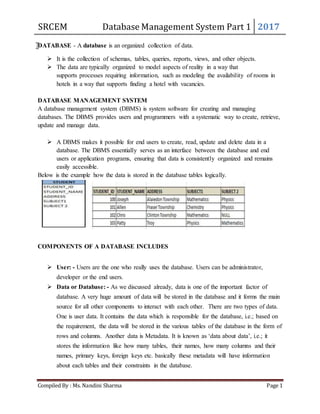
  • 1. SRCEM Database Management System Part 1 2017 Compiled By : Ms. Nandini Sharma Page 1 DATABASE - A database is an organized collection of data.  It is the collection of schemas, tables, queries, reports, views, and other objects.  The data are typically organized to model aspects of reality in a way that supports processes requiring information, such as modeling the availability of rooms in hotels in a way that supports finding a hotel with vacancies. DATABASE MANAGEMENT SYSTEM A database management system (DBMS) is system software for creating and managing databases. The DBMS provides users and programmers with a systematic way to create, retrieve, update and manage data.  A DBMS makes it possible for end users to create, read, update and delete data in a database. The DBMS essentially serves as an interface between the database and end users or application programs, ensuring that data is consistently organized and remains easily accessible. Below is the example how the data is stored in the database tables logically. COMPONENTS OF A DATABASE INCLUDES  User: - Users are the one who really uses the database. Users can be administrator, developer or the end users.  Data or Database: - As we discussed already, data is one of the important factor of database. A very huge amount of data will be stored in the database and it forms the main source for all other components to interact with each other. There are two types of data. One is user data. It contains the data which is responsible for the database, i.e.; based on the requirement, the data will be stored in the various tables of the database in the form of rows and columns. Another data is Metadata. It is known as ‘data about data’, i.e.; it stores the information like how many tables, their names, how many columns and their names, primary keys, foreign keys etc. basically these metadata will have information about each tables and their constraints in the database.
  • 2. SRCEM Database Management System Part 1 2017 Compiled By : Ms. Nandini Sharma Page 2  DBMS: - This is the software helps the user to interact with the database. It allows the users to insert, delete, update or retrieve the data. All these operations are handled by query languages like MySQL, Oracle etc.  Database Application: - It the application program which helps the users to interact with the database by means of query languages. Database application will not have any idea about the underlying DBMS. At very high level, a database is considered as shown in below diagram. Let us see them in detail below.  Applications: - It can be considered as a user friendly web page where the user enters the requests. Here he simply enters the details that he needs and presses buttons to get the data.  End User: - They are the realusers of the database. They can be developers, designers, administrator or the actual users of the database.  DDL: - Data Definition Language (DDL) is a query fired to create database,schema,tables, mappings etc in the database. These are the commands used to create the objects like tables, indexes in the database for the first time. In other words, they create structure of the database.  DDL Compiler: - This part of database is responsible for processing the DDL commands. That means these compiler actually breaks down the command into machine understandable codes. It is also responsible for storing the metadata information like table name, space used by it, number of columns in it, mapping information etc.  DML Compiler: - When the user inserts, deletes, updates or retrieves the record from the database,he will be sending request which he understands by pressing some buttons. But for the database to work/understand the request, it should be broken down to object code. This is done by this compiler. One can imagine this as when a person is asked some question, how this is broken down into waves to reach the brain!  Query Optimizer: - When user fires some request, he is least bothered how it will be fired on the database. He is not all aware of database or its way of performance. But whatever be the request, it should be efficient enough to fetch,insert, update or delete the data from the database. The query optimizer decides the best way to execute the user request which is received from the DML compiler. It is similar to selecting the best nerve to carry the waves to brain!
  • 3. SRCEM Database Management System Part 1 2017 Compiled By : Ms. Nandini Sharma Page 3  Stored Data Manager: - This is also known as Database Control System. It is one the main central system of the database. It is responsible for various tasks o It converts the requests received from query optimizer to machine understandable form. It makes actualrequest inside the database. It is like fetching the exact part of the brain to answer. o It helps to maintain consistency and integrity by applying the constraints. That means, it does not allow inserting / updating / deleting any data if it has child entry. Similarly it does not allow entering any duplicate value into database tables. o It controls concurrent access. If there is multiple users accessing the database at the same time, it makes sure, all of them see correct data. It guarantees that there is no data loss or data mismatch happens between the transactions of multiple users. o It helps to backup the database and recover data whenever required. Since it is a huge database and when there is any unexpected exploit of transaction, and reverting the changes are not easy. It maintains the backup of all data,so that it can be recovered.  Data Files: - It has the realdata stored in it. It can be stored as magnetic tapes,magnetic disks or optical disks.  Compiled DML: - Some of the processed DML statements (insert, update, delete) are stored in it so that if there is similar requests,it will be re-used.  Data Dictionary: - It contains all the information about the database. As the name suggests, it is the dictionary of all the data items. It contains description of all the tables, view, materialized views, constraints, indexes, triggers etc.
  • 4. SRCEM Database Management System Part 1 2017 Compiled By : Ms. Nandini Sharma Page 4 ADVANTAGES OF DBMS DBMS is developed to cover the drawbacks of the traditional file system. 1. Data Mapping and Access: - DBMS defines the way to map any two related tables by means of primary key –foreign key relationship. Primary key is the column in the table which responsible for uniquely identifying each record in the table. Foreign key is the column in the table which is a primary key in other table and with which the entries in the current table are related to other table. For example, in the new database system,we can Student and Student_Report table as follows. STUDENT_ID is the unique using which we can identify each student and hence it forms a primary key in STUDENT table. Similarly, REPORT_ID is the primary key in the STUDENT_REPORT table. STUDENT_ID in the STUDENT_REPORT table is the foreign key. It links STUDENT and STUDENT_REPORT tables. Because of such mapping, it becomes each for the programmer to search for related tables, join them, and fire the query as per the requirement. This reduces the time consumed while searching and mapping these tables. Even when there is large amount of data, the time consumed to retrieve, insert, update or delete is very less. Hence there is no data isolation in the system. Note: Mapping of tables is usually done when they are created. 2. Data Redundancy: - By the introduction of primary key in the table, data redundancy problem is reduced to great extent. As we saw,primary key is the unique column for each record, when there is a re-entry of same record,it does not allow saving such records. DBMS has strong designing techniques like normalization which makes sure the same copy of data is not stored in same table or in multiple tables. It makes sure all the informations are stored only once in the
  • 5. SRCEM Database Management System Part 1 2017 Compiled By : Ms. Nandini Sharma Page 5 database tables.We can see the difference in the way data is being stored in the file and database system. Primary key, foreign keys are defined; unnecessary columns are removed from the STUDENT_REPORT table in the database system. These are missing in the file processing system. 3. Data Independence and Consistency: - DBMS defines a standard to represent the data in the form of rows and columns. It also stores the information about the tables, columns, keys, storage space,used space,available space etc separately from the logical data. Hence they totally independent of the way they are stored and the data being stored. Any changes to the physical storage (like disks, tapes etc) or structure, does not harm the data being stored. Since DBMS defines each columns and rows at the beginning itself and controls the way data being entered, there is no affect on the programs or any other tables or data. Hence the consistency of the data also maintained. If there is a change in the address of any student, we just have to update it in the Student table. There is no other place his information is being stored. Hence it maintains the consistent data in the database. Suppose there is a new column addition to STUDENT table, say DOB. This will change the metadata to reflect additional column in the table structure. It will hardly affect the application unless until there is a new requirement to have transaction with DOB. Hence data independence is also assured in the database. 4. Security: - DBMS allows different levels of access to different users based on their roles. In the school database,individual students will have access to their data alone, while their teachers will have access to all the students whom they are teaching and for the subjects that they are teaching. Class teacher will be able to see the reports of all the students in that class, but not other classes. Similarly, in a banking system, individual account holder will have Read-Only access to their account. While accountant can update, individual account details for each of their transaction. All these levels of security and access are not allowed in file system. 5. Integrity: - DBMS allows having restrictions on individual columns. It would be defined while designing the table itself. If we want to enter salary of an employee within the range 10000 to 40000, we can impose this while designing the table by using CHECK constraint. When salary is entered, it will automatically check for the range specified. CREATE TABLE EMPLOYEE ……….. CONSTRAINT chk_salary CHECK (salary>10000 AND salary <40000) 6. Atomicity: - DBMS makes sure either the transaction is fully complete or it is rolled back to the previous committed state. It does not allow the system to be in a partially committed state. In our example above, DBMS commits marks change transaction before calculating the total. If there is any crash or shutdown of the system, before committing the marks, then updated marks will be rolled back to the original marks. Hence it makes sure atomicity of the transaction is achieved. 7. Concurrent Access: - DBMS provide access to multiple users to access the database at the same time. It has its own mechanism to have concurrency accesses and hence avoid any incorrect data in the system.
  • 6. SRCEM Database Management System Part 1 2017 Compiled By : Ms. Nandini Sharma Page 6 DISADVANTAGES OF DBMS 1. It is bit complex. Since it supports multiple functionality to give the user the best, the underlying software has become complex. The designers and developers should have thorough knowledge about the software to get the most out of it. 2. Because of its complexity and functionality, it uses large amount of memory. It also needs large memory to run efficiently. 3. DBMS system works on the centralized system, i.e.; all the users from all over the world access this database. Hence any failure of the DBMS, will impact all the users. 4. DBMS is generalized software,i.e.; it is written work on the entire systems rather specific one. Hence some of the application will run slow. TYPES OF DATABASE LANGUAGES 1. Data Definition of Language (DDL), which deals with database schemas and description, of how the data should reside in the database.  CREATE – to create database and its object like (table, index, views, store, function)  ALTER – alters the structure of the existing database.
  • 7. SRCEM Database Management System Part 1 2017 Compiled By : Ms. Nandini Sharma Page 7  DROP – to delete objects from the database.  TRUNCATE – remove all records from a table, including all spaces allocated for the records are removed.  COMMENT – add comment to the data dictionary.  RENAME- renames an object. 2. Data Manipulation Language (DML) which deals with data manipulation, and includes most common SQL statements such SELECT,INSERT,UPDATE,DELETE etc, and it is used to store , modify, retrieve, delete and update data in database.  SELECT- retrieve data from the database.  INSERT – insert data into a table.  UPDATE – updates existing data within a table.  DELETE – Delete all records form a database table.  MERGE – UPSERT operation (insert or update).  CALL- call a PL/SQL or Java subprogram.  EXPLAIN PLAN – interpretation of the data access path.  LOCK TABLE- concurrency control. 3. Data Control Languages (DCL) which includes commands such as GRANT, and mostly concerned with rights, permissions and other controls of the database system.  GRANT – allow users access privileges to database.  REVOKE – withdraw user’s access privileges given by using the GRANT command. 4. Tool Command Language – Transactional Control Language which deals with transaction within a database.  COMMIT – commits a transaction.  ROLLBACK – rollback a transaction in a case of any errors.  SAVEPOINT – to rollback transaction making point within a group.  SET TRANSACTIONS – specify characteristics for the transaction. DATA MODELS
  • 8. SRCEM Database Management System Part 1 2017 Compiled By : Ms. Nandini Sharma Page 8 E-R Diagram ER-Diagram is a visual representation of data that describes how data is related to each other.
  • 9. SRCEM Database Management System Part 1 2017 Compiled By : Ms. Nandini Sharma Page 9 Symbols and Notations
  • 10. SRCEM Database Management System Part 1 2017 Compiled By : Ms. Nandini Sharma Page 10 Components of E-R Diagram The E-R diagram has three main components. 1) Entity An Entity can be any object, place, person or class. In E-R Diagram, an entity is represented using rectangles. Consider an example of an Organization. Employee, Manager, Department, Product and many more can be taken as entities from an Organization. Weak Entity Weak entity is an entity that depends on another entity. Weak entity doen't have key attribute of their own. Double rectangle represents weak entity.
  • 11. SRCEM Database Management System Part 1 2017 Compiled By : Ms. Nandini Sharma Page 11 2) Attribute An Attribute describes a property or characteristic of an entity. For example, Name, Age, Address etc can be attributes of a Student. An attribute is represented using eclipse. Key Attribute Key attribute represents the main characteristic of an Entity. It is used to represent Primary key. Ellipse with underlying lines represent Key Attribute. Composite Attribute An attribute can also have their own attributes. These attributes are known as Composite attribute.
  • 12. SRCEM Database Management System Part 1 2017 Compiled By : Ms. Nandini Sharma Page 12 3) Relationship A Relationship describes relations between entities. Relationship is represented using diamonds. There are three types of relationship that exist between Entities.  Binary Relationship  Recursive Relationship  Ternary Relationship
  • 13. SRCEM Database Management System Part 1 2017 Compiled By : Ms. Nandini Sharma Page 13 Binary Relationship Binary Relationship means relation between two Entities. This is further divided into three types. 1. One to One : This type of relationship is rarely seen in real world. The above example describes that one student can enroll only for one course and a course will also have only one Student. This is not what you will usually see in relationship. 2. One to Many : It reflects business rule that one entity is associated with many number of same entity. The example for this relation might sound a little weird, but this menas that one student can enroll to many courses, but one course will have one Student.
  • 14. SRCEM Database Management System Part 1 2017 Compiled By : Ms. Nandini Sharma Page 14 The arrows in the diagram describes that one student can enroll for only one course. 3. Many to One : It reflects business rule that many entities can be associated with just one entity. For example, Student enrolls for only one Course but a Course can have many Students. 4. Many to Many :
  • 15. SRCEM Database Management System Part 1 2017 Compiled By : Ms. Nandini Sharma Page 15 The above diagram represents that many students can enroll for more than one courses. Recursive Relationship When an Entity is related with itself it is known as Recursive Relationship. Ternary Relationship Relationship of degree three is called Ternary relationship.
  • 16. SRCEM Database Management System Part 1 2017 Compiled By : Ms. Nandini Sharma Page 16 ER Model is represented by means of an ER diagram. Any object, for example, entities, attributes of an entity, relationship sets, and attributes of relationship sets, can be represented with the help of an ER diagram. Entity Entities are represented by means of rectangles. Rectangles are named with the entity set they represent. Attributes Attributes are the properties of entities. Attributes are represented by means of ellipses. Every ellipse represents one attribute and is directly connected to its entity (rectangle). If the attributes are composite, they are further divided in a tree like structure. Every node is then connected to its attribute. That is, composite attributes are represented by ellipses that are connected with an ellipse.
  • 17. SRCEM Database Management System Part 1 2017 Compiled By : Ms. Nandini Sharma Page 17 Multivalued attributes are depicted by double ellipse. Derived attributes are depicted by dashed ellipse. Relationship Relationships are represented by diamond-shaped box. Name of the relationship is written inside the diamond-box. All the entities (rectangles) participating in a relationship, are connected to it by a line. Binary Relationship and Cardinality A relationship where two entities are participating is called a binary relationship. Cardinality is the number of instance of an entity from a relation that can be associated with the relation.  One-to-one − When only one instance of an entity is associated with the relationship, it is marked as '1:1'. The following image reflects that only one instance of each entity should be associated with the relationship. It depicts one-to-one relationship.
  • 18. SRCEM Database Management System Part 1 2017 Compiled By : Ms. Nandini Sharma Page 18  One-to-many − When more than one instance of an entity is associated with a relationship, it is marked as '1:N'. The following image reflects that only one instance of entity on the left and more than one instance of an entity on the right can be associated with the relationship. It depicts one-to-many relationship.  Many-to-one − When more than one instance of entity is associated with the relationship, it is marked as 'N:1'. The following image reflects that more than one instance of an entity on the left and only one instance of an entity on the right can be associated with the relationship. It depicts many-to-one relationship.
  • 19. SRCEM Database Management System Part 1 2017 Compiled By : Ms. Nandini Sharma Page 19  Many-to-many − The following image reflects that more than one instance of an entity on the left and more than one instance of an entity on the right can be associated with the relationship. It depicts many-to-many relationship. Participation Constraints  Total Participation − Each entity is involved in the relationship. Total participation is represented by double lines.  Partial participation − Not all entities are involved in the relationship. Partial participation is represented by single lines. The ER Model has the power of expressing database entities in a conceptual hierarchical manner. As the hierarchy goes up, it generalizes the view of entities, and as we go deep in the hierarchy, it gives us the detail of every entity included. Going up in this structure is called generalization, where entities are clubbed together to represent a more generalized view. For example, a particular student named Mira can be generalized along with all the students. The entity shall be a student, and further, the student is a person. The reverse is called specialization where a person is a student, and that student is Mira. Generalization As mentioned above, the process of generalizing entities, where the generalized entities contain the properties of all the generalized entities, is called generalization. In generalization, a number
  • 20. SRCEM Database Management System Part 1 2017 Compiled By : Ms. Nandini Sharma Page 20 of entities are brought together into one generalized entity based on their similar characteristics. For example, pigeon, house sparrow, crow and dove can all be generalized as Birds. Specialization Specialization is the opposite of generalization. In specialization, a group of entities is divided into sub-groups based on their characteristics. Take a group ‘Person’ for example. A person has name, date of birth, gender, etc. These properties are common in all persons, human beings. But in a company, persons can be identified as employee, employer, customer, or vendor, based on what role they play in the company. Similarly, in a school database, persons can be specialized as teacher, student, or a staff, based on what role they play in school as entities. Inheritance We use all the above features of ER-Model in order to create classes of objects in object-oriented programming. The details of entities are generally hidden from the user; this process known as abstraction. Inheritance is an important feature of Generalization and Specialization. It allows lower-level entities to inherit the attributes of higher-level entities.
  • 21. SRCEM Database Management System Part 1 2017 Compiled By : Ms. Nandini Sharma Page 21 For example, the attributes of a Person class such as name, age, and gender can be inherited by lower-level entities such as Student or Teacher. OBJECT ORIENTED DATA MODEL An object database (also object-oriented database management system, OODBMS) is a database management system in which information is represented in the form of objects as used in object- oriented programming. Object databases are different from relational databases which are table- oriented. Object-relational databases are a hybrid of both approaches.
  • 22. SRCEM Database Management System Part 1 2017 Compiled By : Ms. Nandini Sharma Page 22 Object-oriented database management systems (OODBMSs) combines database capabilities with object-oriented programming language capabilities. OODBMSs allow object-oriented programmers to develop the product, store them as objects, and replicate or modify existing objects to make new objects within the OODBMS. Because the database is integrated with the programming language, the programmer can maintain consistency within one environment, in that both the OODBMS and the programming language will use the same model of representation. Relational DBMS projects, by way of contrast, maintain a clearer division between the database model and the application. As the usage of web-based technology increases with the implementation of Intranets and extranets, companies have a vested interest in OODBMSs to display their complex data. Using a DBMS that has been specifically designed to store data as objects gives an advantage to those companies that are geared towards multimedia presentation or organizations that utilize computer-aided design (CAD). Some object-oriented databases are designed to work well with object-oriented programming languages such as Delphi, Ruby, Python, Perl, Java, C#, Visual Basic .NET, C++, Objective- C and Smalltalk; others such as JADE have their own programming languages. OODBMSs use exactly the same model as object-oriented programming languages. Relational Data Model Relational data model is the primary data model, which is used widely around the world for data storage and processing. This model is simple and it has all the properties and capabilities required to process data with storage efficiency. Concepts Tables − In relational data model, relations are saved in the format of Tables. This format stores the relation among entities. A table has rows and columns, where rows represents records and columns represent the attributes. Tuple − A single row of a table, which contains a single record for that relation is called a tuple. Relation instance − A finite set of tuples in the relational database system represents relation instance. Relation instances do not have duplicate tuples. Relation schema − A relation schema describes the relation name (table name), attributes, and their names. Relation key − Each row has one or more attributes, known as relation key, which can identify the row in the relation (table) uniquely.
  • 23. SRCEM Database Management System Part 1 2017 Compiled By : Ms. Nandini Sharma Page 23 Attribute domain − Every attribute has some pre-defined value scope, known as attribute domain. Constraints Every relation has some conditions that must hold for it to be a valid relation. These conditions are called Relational Integrity Constraints. There are three main integrity constraints −  Key constraints  Domain constraints  Referential integrity constraints Key Constraints There must be at least one minimal subset of attributes in the relation, which can identify a tuple uniquely. This minimal subset of attributes is called key for that relation. If there are more than one such minimal subsets, these are called candidate keys. Key constraints force that −  in a relation with a key attribute, no two tuples can have identical values for key attributes.  a key attribute cannot have NULL values. Key constraints are also referred to as Entity Constraints. Domain Constraints Attributes have specific values in real-world scenario. For example, age can only be a positive integer. The same constraints have been tried to employ on the attributes of a relation. Every attribute is bound to have a specific range of values. For example, age cannot be less than zero and telephone numbers cannot contain a digit outside 0-9. Referential integrity Constraints Referential integrity constraints work on the concept of Foreign Keys. A foreign key is a key attribute of a relation that can be referred in other relation. Referential integrity constraint states that if a relation refers to a key attribute of a different or same relation, then that key element must exist.
  • 24. SRCEM Database Management System Part 1 2017 Compiled By : Ms. Nandini Sharma Page 24 In this model, data is organised in two-dimesional tables called relations. The tables or relation are related to each other. Hierarchical Model In this model each entity has only one parent but can have several children. At the top of hierarchy there is only one entity which is called Root.
  • 25. SRCEM Database Management System Part 1 2017 Compiled By : Ms. Nandini Sharma Page 25 Network Model In the network model, entities are organized in a graph, in which some entities can be accessed through several path. DBA Responsibilities  Installation, configuration and upgrading of Microsoft SQL Server/MySQL/Oracle server software and related products.  Evaluate MSSQL/MySQL/Oracle features and MSSQL/MySQL/Oracle related products.  Establish and maintain sound backup and recovery policies and procedures.  Take care of the Database design and implementation.  Implement and maintain database security (create and maintain users and roles, assign privileges).  Database tuning and performance monitoring.  Application tuning and performance monitoring.  Setup and maintain documentation and standards.  Plan growth and changes (capacity planning).  Work as part of a team and provide 7×24 supports when required.  Do general technical trouble shooting and give consultation to development teams.  Interface with MSSQL/MySQL/Oracle for technical support.  ITIL Skill set requirement (Problem Management/Incident Management/Chain Management etc)
  • 26. SRCEM Database Management System Part 1 2017 Compiled By : Ms. Nandini Sharma Page 26 Types of DBA 1. Administrative DBA – Work on maintaining the server and keeping it running. Concerned with backups, security, patches, replication, etc. Things that concern the actual server software. 2. Development DBA – works on building queries, stored procedures, etc. that meet business needs. This is the equivalent of the programmer. You primarily write T-SQL. 3. Architect – Design schemas. Build tables, FKs, PKs, etc. Work to build a structure that meets the business needs in general. The design is then used by developers and development DBAs to implement the actual application. 4. Data Warehouse DBA – Newer role, but responsible for merging data from multiple sources into a data warehouse. May have to design warehouse, but cleans, standardizes, and scrubs data before loading. In SQL Server, this DBA would use DTS heavily. 5. OLAP DBA – Builds multi-dimensional cubes for decision support or OLAP systems. The primary language in SQL Server is MDX, not SQL here Application DBA- Application DBAs straddle the fence between the DBMS and the application software and are responsible for ensuring that the application is fully optimized for the database and vice versa. They usually manage all the application components that interact with the database and carry out activities such as application installation and patching, application upgrades, database cloning, building and running data cleanup routines, data load process management, etc. Types of keys in DBMS  Primary Key – A primary is a column or set of columns in a table that uniquely identifies tuples (rows) in that table.  Super Key – A super key is a set of one of more columns (attributes) to uniquely identify rows in a table.  Candidate Key – A super key with no redundant attribute is known as candidate key  Alternate Key – Out of all candidate keys, only one gets selected as primary key, remaining keys are known as alternate or secondary keys.  Composite Key – A key that consists of more than one attribute to uniquely identify rows (also known as records & tuples) in a table is called composite key.  Foreign Key – Foreign keys are the columns of a table that points to the primary key of another table. They act as a cross-reference between tables.
  • 27. SRCEM Database Management System Part 1 2017 Compiled By : Ms. Nandini Sharma Page 27 Three levels of database architecture 1. Physical Level 2. Conceptual Level 3. External Level In the above diagram,  It shows the architecture of DBMS.  Mapping is the process of transforming request response between various database levels of architecture.  Mapping is not good for small database, because it takes more time.  In External / Conceptual mapping, DBMS transforms a request on an external schema against the conceptual schema.  In Conceptual / Internal mapping, it is necessary to transform the request from the conceptual to internal levels.
  • 28. SRCEM Database Management System Part 1 2017 Compiled By : Ms. Nandini Sharma Page 28 1. Physical Level  Physical level describes the physical storage structure of data in database.  It is also known as Internal Level.  This level is very close to physical storage of data.  At lowest level, it is stored in the form of bits with the physical addresses on the secondary storage device.  At highest level, it can be viewed in the form of files.  The internal schema defines the various stored data types. It uses a physical data model. 2. Conceptual Level  Conceptual level describes the structure of the whole database for a group of users.  It is also called as the data model.  Conceptual schema is a representation of the entire content of the database.  These schema contains all the information to build relevant external records.  It hides the internal details of physical storage. 3. External Level  External level is related to the data which is viewed by individual end users.  This level includes a no. of user views or external schemas.  This level is closest to the user.  External view describes the segment of the database that is required for a particular user group and hides the rest of the database from that user group. Client/Server Architecture In the Oracle client/server architecture, the database application and the database are separated into two parts: a front-end or client portion, and a back-end or server portion. The client executes the database application that accesses database information and interacts with a user through the keyboard, screen, and pointing device such as a mouse. The server executes the Oracle software and handles the functions required for concurrent, shared data access to an Oracle database. Although the client application and Oracle can be executed on the same computer, it may be more efficient and effective when the client portion(s) and server portion are executed by different computers connected via a network. The following sections discuss possible variants in the Oracle client/server architecture. Note: In a distributed database, one server (Oracle) may need to access a database on another server. In this case, the server requesting the information is a client. "Distributed Databases", for more information about clients and servers in distributed databases.
  • 29. SRCEM Database Management System Part 1 2017 Compiled By : Ms. Nandini Sharma Page 29 Distributed Processing Distributed processing is the use of more than one processor to divide the processing for an individual task. The following are examples of distributed processing in Oracle database systems:  The client and server are located on different computers; these computers are connected via a network (see Figure 20 - 1, Part A).  A single computer has more than one processor, and different processors separate the execution of the client application from Oracle (see Figure 20 - 1, Part B).
  • 30. SRCEM Database Management System Part 1 2017 Compiled By : Ms. Nandini Sharma Page 30 Figure 20 - 1. The Client/Server Architecture and Distributed Processing Benefits of the Oracle client/server architecture in a distributed processing environment include the following:  Client applications are not responsible for performing any data processing. Client applications can concentrate on requesting input from users, requesting desired data from the server, and then analyzing and presenting this data using the display capabilities of the client workstation or the terminal (for example, using graphics or spreadsheets).  Client applications can be designed with no dependence on the physical location of the data. If the data is moved or distributed to other database servers, the application continues to function with little or no modification.  Oracle exploits the multitasking and shared-memory facilities of its underlying operating system. As a result, it delivers the highest possible degree of concurrency, data integrity, and performance to its client applications.  Client workstations or terminals can be optimized for the presentation of data (for example, by providing graphics and mouse support) and the server can be optimized for the processing and storage of data (for example, by having large amounts of memory and disk space).  If necessary, Oracle can be scaled. As your system grows, you can add multiple servers to distribute the database processing load throughout the network (horizontally scaled). Alternatively, you can replace Oracle on a less powerful computer, such as a microcomputer, with Oracle running on a minicomputer or mainframe, to take advantage of a larger system's performance (vertically scaled). In either case, all data and applications are maintained with little or no modification, since Oracle is portable between systems.  In networked environments, shared data is stored on the servers, rather than on all computers in the system. This makes it easier and more efficient to manage concurrent access.  In networked environments, inexpensive, low-end client workstations can be used to access the remote data of the server effectively.  In networked environments, client applications submit database requests to the server using SQL statements. Once received, the SQL statement is processed by the server, and the results are returned to the client application. Network traffic is kept to a minimum because only the requests and the results are shipped over the network.
  • 31. SRCEM Database Management System Part 1 2017 Compiled By : Ms. Nandini Sharma Page 31 Sequential File Organization It is one of the simple methods of file organization. Here each file/records are stored one after the other in a sequential manner. This can be achieved in two ways:  Records are stored one after the other as they are inserted into the tables. This method is calledpile file method. When a new record is inserted, it is placed at the end of the file. In the case of any modification or deletion of record, the record will be searched in the memory blocks. Once it is found, it will be marked for deleting and new block of record is entered. Inserting a new record: In the diagram above, R1, R2, R3 etc are the records. They contain all the attribute of a row. i.e.; when we say student record, it will have his id, name, address, course, DOB etc. Similarly R1, R2, R3 etc can be considered as one full set of attributes.  In the second method, records are sorted (either ascending or descending) each time they are inserted into the system. This method is called sorted file method. Sorting of records may be based on the primary key or on any other columns. Whenever a new record is inserted, it will be inserted at the end of the file and then it will sort – ascending or descending based on key value and placed at the correct position. In the case of update, it
  • 32. SRCEM Database Management System Part 1 2017 Compiled By : Ms. Nandini Sharma Page 32 will update the record and then sort the file to place the updated record in the right place. Same is the case with delete. Inserting a new record: Advantages of Sequential File Organization  The design is very simple compared other file organization. There is no much effort involved to store the data.  When there are large volumes of data, this method is very fast and efficient. This method is helpful when most of the records have to be accessed like calculating the grade of a student, generating the salary slips etc where we use all the records for our calculations  This method is good in case of report generation or statistical calculations.  These files can be stored in magnetic tapes which are comparatively cheap. Disadvantages of Sequential File Organization  Sorted file method always involves the effort for sorting the record. Each time any insert/update/ delete transaction is performed, file is sorted. Hence identifying the record, inserting/ updating/ deleting the record, and then sorting them always takes some time and may make system slow.
  • 33. SRCEM Database Management System Part 1 2017 Compiled By : Ms. Nandini Sharma Page 33 Indexed Sequential Access Method (ISAM) This is an advanced sequential file organization method. Here records are stored in order of primary key in the file. Using the primary key, the records are sorted. For each primary key, an index value is generated and mapped with the record. This index is nothing but the address of record in the file. In this method, if any record has to be retrieved, based on its index value, the data block address is fetched and the record is retrieved from memory. Advantages of ISAM  Since each record has its data block address, searching for a record in larger database is easy and quick. There is no extra effort to search records. But proper primary key has to be selected to make ISAM efficient.  This method gives flexibility of using any column as key field and index will be generated based on that. In addition to the primary key and its index, we can have index generated for other fields too. Hence searching becomes more efficient, if there is search based on columns other than primary key.
  • 34. SRCEM Database Management System Part 1 2017 Compiled By : Ms. Nandini Sharma Page 34  It supports range retrieval, partial retrieval of records. Since the index is based on the key value, we can retrieve the data for the given range of values. In the same way, when a partial key value is provided, say student names starting with ‘JA’ can also be searched easily. Disadvantages of ISAM  An extra cost to maintain index has to be afforded. i.e.; we need to have extra space in the disk to store this index value. When there is multiple key-index combinations, the disk space will also increase. As the new records are inserted, these files have to be restructured to maintain the sequence. Similarly, when the record is deleted, the space used by it needs to be released. Else, the performance of the database will slow down. Hash/Direct File Organization In this method of file organization, hash function is used to calculate the address of the block to store the records. The hash function can be any simple or complex mathematical function. The hash function is applied on some columns/attributes – either key or non-key columns to get the block address. Hence each record is stored randomly irrespective of the order they come. Hence this method is also known as Direct or Random file organization. If the hash function is generated on key column, then that column is called hash key, and if hash function is generated on non-key column, then the column is hash column. When a record has to be retrieved, based on the hash key column, the address is generated and directly from that address whole record is retrieved. Here no effort to traverse through whole file. Similarly when a new record has to be inserted, the address is generated by hash key and record
  • 35. SRCEM Database Management System Part 1 2017 Compiled By : Ms. Nandini Sharma Page 35 is directly inserted. Same is the case with update and delete. There is no effort for searching the entire file nor sorting the files. Each record will be stored randomly in the memory. These types of file organizations are useful in online transaction systems, where retrieval or insertion/updation should be faster. Advantages of Hash File Organization  Records need not be sorted after any of the transaction. Hence the effort of sorting is reduced in this method.  Since block address is known by hash function, accessing any record is very faster. Similarly updating or deleting a record is also very quick.  This method can handle multiple transactions as each record is independent of other. i.e.; since there is no dependency on storage location for each record, multiple records can be accessed at the same time.  It is suitable for online transaction systems like online banking, ticket booking system etc. Disadvantages of Hash File Organization  This method may accidentally delete the data. For example, In Student table, when hash field is on the STD_NAME column and there are two same names – ‘Antony’, then same address is generated. In such case, older record will be overwritten by newer. So there will be data loss. Thus hash columns needs to be selected with utmost care. Also, correct backup and recovery mechanism has to be established.
  • 36. SRCEM Database Management System Part 1 2017 Compiled By : Ms. Nandini Sharma Page 36  Since all the records are randomly stored, they are scattered in the memory. Hence memory is not efficiently used.  If we are searching for range of data, then this method is not suitable. Because, each record will be stored at random address. Hence range search will not give the correct address range and searching will be inefficient. For example, searching the employees with salary from 20K to 30K will be efficient.  Searching for records with exact name or value will be efficient. If the Student name starting with ‘B’ will not be efficient as it does not give the exact name of the student.  If there is a search on some columns which is not a hash column, then the search will not be efficient. This method is efficient only when the search is done on hash column. Otherwise, it will not be able find the correct address of the data.  If there is multiple hash columns – say name and phone number of a person, to generate the address, and if we are searching any record using phone or name alone will not give correct results.  If these hash columns are frequently updated, then the data block address is also changed accordingly. Each update will generate new address. This is also not acceptable. Hardware and software required for the memory management are costlier in this case. Complex programs needs to be written to make this method efficient.