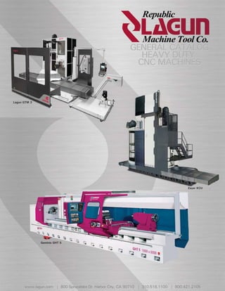
1. Lagun GTM 3
Zayer KCU
Geminis GHT 5
www.lagun.com | 800 Sprucelake Dr. Harbor City, CA 90710 | 310.518.1100 | 800.421.2105
2. REPUBLIC LAGUN MACHINE TOOL CO.
LEADING THE INDUSTRY FOR OVER 40 YEARS
Republic Lagun Machine Tool Company was founded in 1968 and is located in
Harbor City, California. Our Sales, Manufacturing and Distribution Facility occupies over
30,000 square feet. Republic Lagun’s Manual and CNC Milling Machines, Lathes and CNC
IRON & STEEL
Machining Centers have been supplied to the Aerospace, Alternative Energy, Construction,
Defense, Electronic, Iron and Steel, Medical, Oil and Gas, Power Generation and Railroad
Industries. Having over 70,000 installed machines, stocking over $3,000,000 in parts and
accessories, we provide our customers with superior
manufacturing solutions and single source responsibility.
MEDICAL
AEROSPACE Republic Lagun’s products are of the highest
quality structures with heavily ribbed construction for
superior rigidity, strength and dimensional stability with
enhanced wear characteristics. The machines are
modular in design, allowing the customer to create
OIL & GAS
ALTERNATIVE ENERGIES custom machines by selecting the Axis
travels, spindle power, automatic tool changers, CNC
Controls and other machine features. Training is
tailored to our client’s requirements, being
conducted at our facilities or in the customer’s factories. POWER GENERATION
CONSTRUCTION
Throughout our history, Republic Lagun has been,
and is, synonymous with productivity, structural
quality magnitude, and superior cutting capability.
More importantly, we meet or exceed our customer’s ex- RAILROAD
DEFENSE pectations and requirements, resulting in customer satis-
faction. Historically, we supply the largest static and dy-
namically rigid machines with the highest available horsepower and thrust. Where performance
counts, in the machining of your parts, we are second to none. This, coupled with our unprec-
edented Product Offerings, will further increase your manufacturing Performance...Productivity…
ELECTRONICS Precision…Profitability.
We look forward to working with you towards your acquisition of machine tools, providing the
technological edge in manufacturing, demanded in the highly competitive 21st century.
4. TRAVELING TABLE MACHINING CENTERS
VELING
360° Multi-Angle Vertical & Horizontal Head Positioning
GBR SPECIFICATION GBR
Features Include Table Length 122 or 161” (3,100 or 4,100 mm)
• Siemens, Heidenhain, Fanuc Control Table Width 39” (1,000 mm)
• Linear Guide Ways On (X, Y & Z-Axes) Table Load Capacity 13,227 or 15,432 lbs (6,000 or 7,000 kg)
• Ball Screws (X, Y & Z-Axes) X-Axis Longitudinal 118 to 154” (3,000 or 4,000 mm)
• Optical Linear Scales (X, Y & Z-Axes) Z-Axis Vertical 59 or 78” (1,500 or 2,000 mm)
• 45° Universal Head
Y-Axis Cross 47” (1,200 mm)
• 360° Multi-Angle Vert. & Horiz. Head Positioning
Main Motor 37 HP (28 kW)
Spindle Speed 50 to 3,000 or 4,000 or 6,000 RPM
Spindle Taper ISO 50 or Big Plus CAT 50
X, Y & Z-Axes Working Feeds .24 to 787 in/min (6 to 20,000 mm/min)
X, Y & Z-Axes Rapid Feeds 787 in/min (20,000 mm/min)
Tool Changer # of Tools 24 to 60
Tool Change Time 20 seconds
1
5. TRAVELING COLUMN MACHINING CENTERS
TRAVELING COLUMN MACHINING CENTERS
360° Multi-Angle Vertical & Horizontal Head Positioning
SPECIFICATION GCM GCM
Table Length 216 to 452” (5,500 to 11,500 mm) Features Include
Table Width 43” (1,100 mm) • Siemens, Heidenhain, Fanuc Control
Table Load Capacity 717 lbs/ft² (3,500 kg/m²) • Linear Guide Ways On The (X, Y & Z-Axes)
• Cylindrical Roller Packs On X-Axis Center Way
X-Axis Longitudinal 157 to 393” (4,000 to 10,000 mm)
• Rack & Dual Motor Driven Pinions (X-Axis)
Z-Axis Vertical 59 or 78” (1,500 or 2,000 mm)
• Ball Screws w/ Double Preloaded Nuts (Y & Z-Axes)
Y-Axis Cross 47” (1,200 mm) • Optical Linear Scales On The (X, Y & Z-Axes)
Main Motor - Continuous / Intermittent 37 / 46 Hp (28 / 34 kW) • 45° Universal Head
Spindle Speed 50 to 3,000 or 4,000 or 6,000 RPM • 360° Multi-Angle Vert. & Horiz. Head Positioning
Spindle Taper ISO 50 or Big Plus CAT 50
X, Y & Z-Axes Working Feeds .24 to 787 in/min (6 to 20,000 mm/min)
X, Y & Z-Axes Rapid Feeds 787 in/min (20,000 mm/min)
Tool Changer # of Tools 24 to 60
Tool Change Time 20 seconds
2
6. ROTARY TABLE MACHINING CENTERS
360° Multi-Angle Vertical & Horizontal Head Positioning
SPECIFICATION GTM
Table Length 59” (1,500 mm)
GTM Table Width 59” (1,500 mm)
Table Load Capacity 22,046 lbs (10,000 kg)
Features Include
X-Axis Longitudinal 78 to 154” (2,000 to 4,000 mm)
• Siemens, Heidenhain, Fanuc Control Z-Axis Vertical 59 or 78” (1,500 or 2,000 mm)
• Linear Guide Ways On The (X, Y, Z & V Axes)
Y-Axis Cross 47” (1,200 mm)
• Cylindrical Roller Packs On The V Axis Center Way
• Ball Screws w/ Double Preloaded Nuts (X, Y, Z & V Axes) V Axis Column 39 or 59” (1,000 or 1,500 mm)
• Optical Linear Scales On The (X, Y, Z & V Axes) Main Motor - Continuous / Intermittent 37 / 46 Hp (28 / 34 kW)
• 45° Universal Head Spindle Speed 50 to 3,000 or 4,000 or 6,000 RPM
• 360° Multi-Angle Vert. & Horiz. Head Positioning Spindle Taper ISO 50 or Big Plus CAT 50
X, Y, Z & V Axes Working Feeds .24 to 787 in/min (6 to 20,000 mm/min)
X, Y, Z & V Axes Rapid Feeds 787 in/min (20,000 mm/min)
Tool Changer # of Tools 30 to 60
Tool Change Time 20 seconds
3
7. TRAVELING COLUMN MACHINING CENTERS
TRAVELING COLUMN MACHINING CENTERS
360° Multi-Angle Vertical & Horizontal Head Positioning
SPECIFICATION GMM GMM
Table Length 157 to 866” (4,000 to 22,000 mm) Features Include
Table Width 59” (1,500 mm) • Siemens, Heidenhain, Fanuc Control
Table Load Capacity 3,073 lbs/ft² (15,000 kg/m²) • Linear Guide Ways On The (X, Y & Z-Axes)
X-Axis Longitudinal 157 to 787” (4,000 to 20,000 mm) • Cylindrical Roller Packs On The X-Axis Center Way
Z-Axis Vertical 59 to 78” (1,500 to 2,000 mm) • Rack & Dual Motor Driven Pinions (X-Axis)
• Ball Screws With Double Preloaded Nuts (Y & Z-Axes)
Y-Axis Cross 47” (1,200 mm)
• Optical Linear Scales On The (X, Y & Z-Axes)
Main Motor - Continuous / Intermittent 37 / 46 Hp (28 / 34 kW)
• 45° Universal Head
Spindle Speed 50 to 3,000 or 4,000 or 6,000 RPM • Spindle Head Changing Capability
Spindle Taper ISO 50 or Big Plus CAT 50 • 360° Multi-Angle Vert. & Horiz. Head Positioning
X, Y & Z-Axes Working Feeds .24 to 787 in/min (6 to 20,000 mm/min)
X, Y & Z-Axes Rapid Feeds 787 in/min (20,000 mm/min)
Tool Changer # of Tools 30 to 60
Tool Change Time 20 seconds
4
8. TRAVELING COLUMN MACHINING CENTERS
GML
Features Include
• Siemens, Heidenhain, Fanuc Control
• Linear Guide Ways On The (X, Y & Z-Axes)
• Cylindrical Roller Packs On The (X-Axis) Center Way
• Rack & Dual Motor Driven Pinions For The X-Axis Longitudinal Travel
• Ball Screws With Double Preloaded Nuts For The (Y & Z-Axes)
• Optical Linear Scales On The (X, Y & Z-Axes)
• 45° Universal Head
• Spindle Head Changing Capability
• 360° Multi-Angle Vert. & Horiz. Head Positioning
SPECIFICATION GML
Table Length 157 to 866” (4,000 to 22,000 mm)
Table Width 78” (2,000 mm)
Table Load Capacity 3,073 lbs/ft² (15,000 kg/m²)
X-Axis Longitudinal 157 to 787” (4,000 to 20,000 mm)
Z-Axis Vertical 98 to 118” (2,500 to 3,000 mm)
Y-Axis Cross 59.05” (1,500 mm)
Main Motor - Continuous / Intermittent 37 / 46 Hp (28 / 34 kW)
Spindle Speed 50 to 3,000 or 4,000 or 6,000 or 8,000 RPM
Spindle Taper ISO 50 or Big Plus CAT 50
X, Y & Z-Axes Working Feeds .24 to 787 or 1,181 in/min (6 to 20,000 or 30,000 mm/min)
• 360° Multi-Angle Vertical
X, Y & Z-Axes Rapid Feeds 787 or 1,181 in/min (20,000 or 30,000 mm/min)
& Horizontal Head Positioning
Tool Changer # of Tools 24 to 60
Tool Change Time 20 seconds
5
9. TRAVELING COLUMN MACHINING CENTERS
SPECIFICATION KMCU KMCU
Table Length 185 to 618” (4,700 to 15,700 mm) Features Include
Table Width 47” (1,200 mm) • Siemens, Heidenhain, Fanuc Control
Table Load Capacity 717 lbs/ft² (3,500 kg/m²) • Fluidic Axis Guideway System
X-Axis Longitudinal 125 to 590” (3,200 to 14,200 mm) • Hardened & Ground Box Guideways
Z-Axis Vertical 59 or 78” (1, 500 or 2,000 mm) • Cylindrical Roller Packs (X, Y & Z-Axes)
Y-Axis Cross 49 or 63” (1,250 or 1,600 mm)
• Rack & Dual Motor Driven Pinions For The (X-Axis)
• Double Preloaded Ball Screw Nuts (Y & Z-Axes)
Main Motor - Continuous 50 Hp (37 kW)
• Optical Linear Scales (X, Y & Z-Axes)
Spindle Speed 6 to 4,500 or 6,000 RPM • Chip Conveyer & Coolant System
Spindle Taper ISO 50 or Big Plus CAT 50 • Refrigeration For The Gear Box, Ram & Head
X, Y & Z-Axes Working Feeds .24 to 590 in/min (6 to 15,000 mm/min) • 45° Universal Head With 360,000° Positioning
X, Y & Z-Axes Rapid Feeds 984 in/min (25,000 mm/min) • Spindle Head Changing Capability
Tool Changer # of Tools 30 to 60
Tool Change Time 10 seconds
6
10. TRAVELING COLUMN MACHINING CENTERS
20 - 30 - 60 KCU SPECIFICATION KCU
Features Include Table Length 196 to 1,220” (5,000 to 31,000 mm)
• Siemens, Heidenhain, Fanuc Control Table Width 78 to 118” (2,000 to 3,000 mm)
• Dual Function Guideway System With Fluidic Axis Support Floor Plate Load Capacity 3,073 lbs/ft² (15,000 kg/m²)
• Hardened & Ground Box Guideways X-Axis Longitudinal 118 to 944” (3,000 to 24,000 mm)
• Cylindrical Roller Packs For The (X Y & Z-Axes)
(X,
Z-Axis Vertical 59 to 196” (1,500 to 5,000 mm)
• Rack & Dual Motor Driven Pinions (X-Axis)
Y-Axis Cross 49 to 63” (1,250 to 1,600 mm)
• Ball Screws With Double Preloaded Nuts For The (Y & Z-Axes)
• Optical Linear Scales On The (X, Y & Z-Axes) Main Motor - Continuous 37 to 80 Hp (28 to 60 kW)
• Chip Conveyer & Coolant System Spindle Speed 6 to 4,500 or 6,000 RPM
• Refrigeration For The Gear Box, Ram & Head Spindle Taper ISO 50 or Big Plus CAT 50
• 45° Universal Head With 360,000° Positioning X, Y & Z-Axes Working Feeds .24 to 393 in/min (6 to 10,000 mm/min)
• Spindle Head Changing Capability
X, Y & Z-Axes Rapid Feeds 787 in/min (20,000 mm/min)
Tool Changer # of Tools 30 to 200
Tool Change Time 10 seconds
7
11. FIXED RAIL BRIDGE MACHINING CENTERS
S
SPECIFICATION KPCU KPCU
T
Table Length 157 to 472” (4,000 to 12,000 mm) Features Include
Table Width
T 78 or 98” (2,000 or 2,500 mm)
• Fixed Rail Bridge
Table Load Capacity
T 22,046 to 44,092 lbs (10,000 to 20,000 kg)
• Siemens, Heidenhain, Fanuc Control
X-Axis Longitudinal
X 157 to 472” (4,000 to 12,000 mm) • Dual Function Guideway System
Y-Axis Cross
Y 139 or 147” (3,550 or 3,750 mm) • Fluidic Axis Support
Z-Axis Vertical
Z 43 or 49” (1,100 or 1,250 mm) • Hardened & Ground Box Guideways
Between The Columns 110 or 118” (2,800 or 3,000 mm) • Cylindrical Roller Packs For The (X, Y & Z-Axes)
Table To Spindle 47 or 53” (1,200 or 1,350 mm)
• Rack & Dual Motor Driven Pinions (X & Y-Axes)
• Ball Screws With Double Preloaded Nuts (Z-Axis)
Main Motor - Continuous 50 Hp (37 kW)
• Optical Linear Scales On The (X, Y & Z-Axes)
Spindle Speed 35 to 4,500 or 6,000 RPM • Chip Conveyer & Coolant System
Spindle Taper ISO 50 or Big Plus CAT 50 • Refrigeration For The Gear Box, Ram & Head
X, Y & Z-Axes Working Feeds .24 to 590 in/min (6 to 15,000 mm/min) • Vertical Spindle Attachment Head
X, Y & Z-Axes Rapid Feeds 984 in/min (25,000 mm/min) • Spindle Head Changing Capability
Tool Changer # of Tools 30 to 120
Tool Change Time 20 seconds
8
12. FIXED & ELEVATING RAIL BRIDGE MACHINING CENTERS
FPCU & FMCU SPECIFICATION FPCU & FMCU
Features Include Table Length 157 to 472” (4,000 to 12,000 mm)
• Fixed & Elevating Rail Bridge Table Width 78 to 157” (2,000 to 4,000 mm)
• Siemens 840D Or Fanuc’s 31i Control Table Load Capacity 33,069 to 77,161 lbs (15,000 to 35,000 kg)
• Dual Function Guideway System w/ Fluidic Axis Support X-Axis Longitudinal 157 to 472” (4,000 to 12,000 mm)
• Hardened & Ground Box Guideways Y-Axis Cross 159 to 218” (4,050 to 5,550 mm)
• Cylindrical Roller Packs For The (X, Y, Z & W-Axes)
Z-Axis Vertical 49 to 59” (1,250 to 1,500 mm)
• Rack & Dual Motor Driven Pinions (X & Y-Axes)
W-Axis – Elevating Rail 66 or 86” (1,700 or 2,200 mm)
• Ball Screws With Double Preloaded Nuts (Z & W-Axes)
• Optical Linear Scales On The (X, Y, Z & W-Axes) Between The Columns 129 to 188” (3,300 to 4,800 mm)
• Chip Conveyer & Coolant System Table To Spindle – Fixed Rail 59 or 71” (1,515 or 1,815 mm)
• Refrigeration For The Gear Box, Ram & Head Table To Spindle – Elevating Rail 75 or 95” (1,915 or 2,415 mm)
• Vertical Spindle Attachment Head Main Motor - Continuous 80 HP (60 kW)
• Spindle Head Changing Capability
Spindle Speed 35 to 4,500 RPM
• 5 Axis Head Optional
Spindle Taper ISO 50 or Big Plus CAT 50
X, Y & Z-Axes Working Feeds .24 to 590 in/min (6 to 15,000 mm/min)
X, Y & Z-Axes Rapid Feeds 984 in/min (25,000 mm/min)
W-Axis Positioning – Elevating Rail 39 in/min (1,000 mm/min)
Tool Changer # of Tools 30 to 120
Tool Change Time 20 seconds
9
13. FIXED & ELEVATING RAIL GANTRY MACHINING CENTERS
SPECIFICATION GPCU & GMCU GPCU & GMCU
Table Length 196 to 1,220” (5,000 to 31,000 mm) Features Include
Table Width 78 to 137” (2,000 to 3,500 mm) • Fixed & Elevating Rail Bridge
Floor Plate Load Capacity 3,073 lbs/ft2 (15,000 kg/m2) • Siemens 840D Or Fanuc’s 31i Control
X-Axis Longitudinal 157 to 1,181” (4,000 to 30,000 mm) • Dual Function Guideway System
Y-Axis Cross 159 to 218” (4,050 to 5,550 mm) • Fluidic Axis Support
Z-Axis Vertical 49 to 98” (1,250 to 2,500 mm)
• Hardened & Ground Box Guideways
• Cylindrical Roller Packs For The (X, Y, Z & W-Axes)
W-Axis – Elevating Rail 47 to 118” (1,200 to 3,000 mm)
• Rack & Dual Motor Driven Pinions (X & Y-Axes)
Between The Columns 129 to 188” (3,300 to 4,800 mm)
• Ball Screws With Double Preloaded Nuts (Z & W-Axes)
Table To Spindle – Fixed Rail 59 or 71” (1,515 or 1,815 mm) • Optical Linear Scales On The (X, Y, Z & W-Axes)
Table To Spindle – Elevating Rail 79 to 150” (2,015 to 3,815 mm) • Chip Conveyer & Coolant System
Main Motor - Continuous 80 to 100 Hp (60 to 75 kW) • Refrigeration For The Gear Box, Ram & Head
Spindle Speed 35 to 4,500 RPM • Vertical Spindle Attachment Head
Spindle Taper ISO 50 or Big Plus CAT 50
• Spindle Head Changing Capability
• Vertical Turning Capability
X, Y & Z-Axes Working Feeds .24 to 393 in/min (6 to 10,000 mm/min)
• 5 Axis Head Optional
X-Axis Rapid Feeds 787 in/min (20,000 mm/min)
Y & Z-Axes Rapid Feeds 984 in/min (25,000 mm/min)
W-Axis Positioning Rate 39 in/min (1,000 mm/min)
Tool Changer # of Tools 30 to 200
Tool Change Time 20 seconds
10
14. HIGH RAIL GANTRY MACHINING CENTERS
MEMPHIS SPECIFICATION MEMPHIS
Features Include Table Length 98 to 767” (2,500 to 19,500 mm)
Table Width 78 or 118” (2,000 or 3,000 mm)
• High Rail Gantry
• Siemens 840D Or Fanuc’s 31i Control Table Load Capacity 3,073 lbs/ft² (15,000 kg/m²)
• Dual Function Guideway System With Fluidic Axis Support X-Axis Longitudinal 118 to 787” (3,000 to 20,000 mm)
• Hardened & Ground Box Guideways Y-Axis Cross 78 or 118” (2,000 or 3,000 mm)
• Cylindrical Roller Packs For The (X, Y & Z-Axes) Z-Axis Vertical 49 or 59” (1,250 or 1,500 mm)
• Rack & Dual Motor Driven Pinions (X & Y-Axes)
Between The Columns 118 or 157” (3,000 or 4,000 mm)
• Dual Ball Screws With Double Preloaded Nuts (Z-Axis)
• Optical Linear Scales On The (X, Y & Z-Axes) Table To Spindle 58 to 77” (1,465 to 1,965 mm)
• Chip Conveyer & Coolant System Main Motor - Continuous 42 or 60 Hp (32 or 45 kW)
• Refrigeration For The Gear Box, Ram & Head Spindle Speed 35 to 6,000 RPM
• 45° Universal Head With 360,000° Positioning Spindle Taper ISO 50 or Big Plus CAT 50
• Spindle Head Changing Capability
X, Y & Z-Axes Working Feeds .24 to 787 in/min (6 to 20,000 mm/min)
• 5 Axis Head Optional
X & Y-Axes Rapid Feeds 1,574 in/min (40,000 mm/min)
Z-Axis Rapid Feed 1,181 in/min (30,000 mm/min)
Tool Changer # of Tools 30 to 120
Tool Change Time 10 seconds
11
15. HIGH SPEED BRIDGE MACHINING CENTERS
SPECIFICATION TEBAS TEBAS
Table Length 165 to 244” (4,200 to 6,200 mm) Features Include
Table Width 86” (2,200 mm)
• High Speed Fixed Rail
Table Load Capacity 44,092 lbs (20,000 kg) • Siemens 840D Or Fanuc’s 31i Control
X-Axis Longitudinal 157 to 236” (4,000 to 6,000 mm) • Linear Guide Ways On The (X, Y & Z-Axes)
Y-Axis Cross 147” (3,750 mm) • Rack & Dual Motor Driven Pinions (X & Y-Axes)
Z-Axis Vertical 49” (1,250 mm)
• Dual Ball Screws With Double Preloaded Nuts (Z-Axis)
• Optical Linear Scales On The (X, Y & Z-Axes)
Between The Columns 118” (3,000 mm)
• Chip Conveyer & Coolant System
Table To Spindle 58” (1,465 mm) • Refrigeration For The Gear Box, Ram & Head
Main Motor - Continuous 42 or 60 Hp (32 or 45 kW) • Vertical Spindle Attachment Head
Spindle Speed 35 to 6,000 RPM • Spindle Head Changing Capability
Spindle Taper ISO 50 or Big Plus CAT 50 • 5 Axis Head Optional
X, Y & Z-Axes Working Feeds .24 to 1,181 in/min (6 to 30,000 mm/min)
X, Y & Z-Axes Rapid Feeds 1,968 in/min (50,000 mm/min)
Tool Changer # of Tools 20 to 60
Tool Change Time 10 seconds
12
16. CNC TURNING CENTER
GHT 4
Features Include Optional
• Siemens Sinumerik 840D Or Fanuc’s 31i CNC • Motor Driven Tool Turret
• 8 Station Disk Turret For 40 VDI Tooling • ID & OD Grinding Attachment
• ZF Headstock Gearbox Drive • Boring Bar System
• G2 Or G4 Bed Way Design • Chucks: Manual or Hydraulic
• X & Z-Axis Ball Screw Drives
• Rotary Encoders For The (X & Z-Axes)
• Chip Pan & Coolant System
SPECIFICATION G2 G4
Maximum Turning Diameter 18” (457.2 mm) 18” (457.2 mm)
Swing Over Bed Ways 28” (720 mm) 31” (800 mm)
Swing Over Cross Slide 18” (457.2 mm) 18” (457.2 mm)
Distance Between Centers 39 to 236” (1,000 to 6,000 mm)
X-Axis Cross Slide 15” (400 mm) 16” (430 mm)
Z-Axis Carriage & Tailstock 39 to 236” (1,000 to 6,000 mm)
Spindle Mount DIN 55026 – 11 or 15
Spindle Drive Continuous & Intermittent 23 / 30 Hp (17 / 23 kW) or 30 / 39 Hp (22 / 30 kW)
Spindle Torque 1,172 to 1,741 lb-ft (1,590 to 2,361 Nm)
Spindle Speed 0 to 1,600 or 2,600 RPM
Maximum Through Hole Diameter 4 to 6” (104 to 162 mm)
Turret Type Disk Turret
Tooling Positions 8 or 12 Positions
Tooling Type 40 VDI
X-Axis Feed & Rapid Rates 314 in/min (8,000 mm/min)
Z-Axis Feed & Rapid Rates 314 in/min (8,000 mm/min)
Quill Diameter 4” (100 mm)
Quill Travel 8” (200 mm) 10” (250 mm)
Unsupported Part Between Centers 5,643 lbs (2,560 kg)
Chuck & Part 10” From The Spindle Nose 1,763 lbs (800 kg)
13
17. CNC TURNING CENTER
GHT 5
Features Include Optional
• Siemens Sinumerik 840D Or Fanuc’s 31i CNC • Motor Driven Tool Turret
• 4 Position Square Head Turret For 1.25” Tooling • ID & OD Grinding Attachment
• ZF Headstock Gearbox Drive • Boring Bar System
• G2 Or G4 Bed Way Design • Chucks: Manual or Hydraulic
• X & Z-Axes Ball Screw Drives
• Rotary Encoders For The (X & Z-Axes)
• Chip Pan & Coolant System
SPECIFICATION G2 G4
Maximum Turning Diameter 26” (680 mm) 27” (700 mm)
Swing Over Bed Ways 39” (1,000 mm)
Swing Over Cross Slide 26” (680 mm) 27” (700 mm)
Distance Between Centers 39 to 314” (1,000 to 8,000 mm)
X-Axis Cross Slide 21” (550 mm) 24” (615 mm)
Z-Axis Carriage & Tailstock 39 to 314” (1,000 to 8,000 mm)
Spindle Mount DIN 55026 – 11 or 15
Spindle Drive Continuous & Intermittent 37 / 45 Hp (28 / 34 kW) or 40 / 50 Hp (30 / 37 kW)
Spindle Torque 2,481 to 3,577 lb-ft (3,365 to 4,850 Nm)
Spindle Speed 0 to 1,400 or 1,600 RPM
Maximum Through Hole Diameter 4 to 6” (104 to 162 mm)
Turret Type Square Head Turret
Tooling Positions 4 to 12 Positions
Tooling Type 1.2” (32 mm)
X-Axis Feed & Rapid Rates 314 in/min (8,000 mm/min)
Z-Axis Feed & Rapid Rates 314 in/min (8,000 mm/min)
Quill Diameter 5” (140 mm)
Quill Travel 11” (300 mm)
Unsupported Part Between Centers 10,582 lbs (4,800 kg)
Chuck & Part 10” From The Spindle Nose 2,645 lbs (1,200 kg)
14
18. CNC TURNING CENTER
GHT 6
Features Include Optional
• Siemens Sinumerik 840D Or Fanuc’s 31i CNC • Motor Driven Tool Turret
• 4 Position Square Head Turret For 1.25” Tooling • ID & OD Grinding Attachment
• ZF Headstock Gearbox Drive • Boring Bar System
• G2 Or G4 Bed Way Design • Chucks: Manual or Hydraulic
• X & Z-Axes Ball Screw Drives
• Rotary Encoders For The (X & Z-Axes)
• Chip Pan & Coolant System
SPECIFICATION G2 G4
Maximum Turning Diameter 37” (940 mm) 39” (1,000 mm)
Swing Over Bed Ways 51” (1,300 mm)
Swing Over Cross Slide 37” (940 mm) 39” (1,000 mm)
Distance Between Centers 39 to 314” (1,000 to 8,000 mm)
X-Axis Cross Slide 26” (680 mm)
Z-Axis Carriage & Tailstock 39 to 314” (1,000 to 8,000 mm)
Spindle Mount DIN 55026 – 11 or 15
Spindle Drive Continuous & Intermittent 50 / 61 Hp (37 / 46 kW) or 68 / 91 Hp (51 / 68 kW)
Spindle Torque 7,375 to 13,497 lb-ft (10,000 to 18,300 Nm)
Spindle Speed 0 to 800 RPM
Maximum Through Hole Diameter 4 to 6” (104 to 162 mm)
Turret Type Square Head Turret
Tooling Positions 4 to 12 Positions
Tooling Type 1.2” (32 mm)
X-Axis Feed & Rapid Rates 314 in/min (8,000 mm/min)
Z-Axis Feed & Rapid Rates 314 in/min (8,000 mm/min)
Quill Diameter 7” (180 mm)
Quill Travel 11” (300 mm)
Unsupported Part Between Centers 22,046 lbs (10,000 kg)
Chuck & Part 10” From The Spindle Nose 5,291 lbs (2,400 kg)
15
19. CNC TURNING CENTER
GHT 7
Features Include Optional
• Siemens Sinumerik 840D Or Fanuc’s 31i CNC • Motor Driven Tool Turret
• 4 Position Square Head Turret For 1.25” Tooling • ID & OD Grinding Attachment
• ZF Headstock Gearbox Drive • Boring Bar System
• G2 Or G4 Bed Way Design • Chucks: Manual or Hydraulic
• (X-Axis) Ball Screw Drive
• (Z-Axis) Rack & Pinion Drive
• Rotary Encoder For The (X-Axis)
• Optical Linear Scale On The (Z-Axis)
• Chip Pan & Coolant System
• Automatic Tailstock Positioning & Manual Clamping
• Live Tailstock Center
SPECIFICATION G2 G4
Maximum Turning Diameter 37” (940 mm) 39” (1,000 mm)
Swing Over Bed Ways 51” (1,300 mm)
Swing Over Cross Slide 37” (940 mm) 39” (1,000 mm)
Distance Between Centers 39 to 708” (1,000 to 18,000 mm)
X-Axis Cross Slide 26” (680 mm)
Z-Axis Carriage & Tailstock 39 to 708” (1,000 to 18,000 mm)
Spindle Mount DIN 55026 – 11 or 15
Spindle Drive Continuous & Intermittent 53 / 67 Hp (40 / 50 kW) or 68 / 91 Hp (51 / 68 kW)
Spindle Torque 7,567 to 13,497 lb-ft (10,260 to 18,300 Nm)
Spindle Speed 0 to 800 RPM
Maximum Through Hole Diameter 4 to 9” (104 to 230 mm)
Turret Type Square Head Turret
Tooling Positions 4 to 12 Positions
Tooling Type 1.2” (32 mm)
X-Axis Feed & Rapid Rates 236 in/min (6,000 mm/min)
Z-Axis Feed & Rapid Rates 314 in/min (8,000 mm/min)
Quill Diameter 7” (180 mm)
Quill Travel 11” (300 mm)
Unsupported Part Between Centers 22,046 lbs (10,000 kg)
Chuck & Part 10” From The Spindle Nose 5,291 lbs (2,400 kg)
16
20. CNC TURNING CENTER
GHT 9
Features Include Optional
• Siemens Sinumerik 840D Or Fanuc’s 31i CNC
• Motor Driven Tool Turret
• 4 Position Square Head Turret For 1.25” Tooling
• ID & OD Grinding Attachment
• ZF Headstock Gearbox Drive
• Boring Bar System
• G2 Or G4 Bed Way Design
• Chucks: Manual or Hydraulic
• (X-Axis) Ball Screw Drives
• (Z-Axis) Rack & Pinion Drive
• Rotary Encoder For The (X-Axis)
• Optical Linear Scale On The (Z-Axis)
• Chip Pan & Coolant System
• Automatic Tailstock Positioning & Manual Clamping
• Live Tailstock Center
• Automatic Tailstock Quill Positioning
• Tailstock Quill Axial Force Measuring
SPECIFICATION G2 G4
Maximum Turning Diameter 48” (1,225 mm) 51” (1,320 mm)
Swing Over Bed Ways 62” (1,600 mm)
Swing Over Cross Slide 48” (1,225 mm) 51” (1,320 mm)
Distance Between Centers 39 to 944” (1,000 to 24,000 mm)
X-Axis Cross Slide 32” (830 mm)
Z-Axis Carriage & Tailstock 39 to 944” (1,000 to 24,000 mm)
Spindle Mount DIN 55026 – 15 or 20
Spindle Drive Continuous & Intermittent 109 / 147 Hp (82 / 109 kW) or 140 / 188 Hp (105 / 140 kW)
Spindle Torque 7,928 to 33,657 lb-ft (10,750 to 45,633 Nm)
Spindle Speed 0 to 550 or 710 RPM
Maximum Through Hole Diameter 9 to 14” (230 to 360 mm)
Turret Type Square Head Turret
Tooling Positions 4 to 12 Positions
Tooling Type 1.2” (32 mm)
X-Axis Feed & Rapid Rates 236 in/min (6,000 mm/min)
Z-Axis Feed & Rapid Rates 236 in/min (6,000 mm/min)
Quill Diameter 9” (240 mm)
Quill Travel 10” (270 mm)
Unsupported Part Between Centers 38,580 lbs (17,500 kg)
Chuck & Part 12” From The Spindle Nose
17
21. CNC TURNING CENTER
GHT 11
Features Include Optional
• Siemens Sinumerik 840D Or Fanuc’s 31i CNC • Motor Driven Tool Turret
• 4 Position Square Head Turret For 1.57” Tooling • ID & OD Grinding Attachment
• ZF Headstock Gearbox Drive • Boring Bar System
• G2 Or G4 Bed Way Design • Chucks: Manual or Hydraulic
• (X-Axis) Ball Screw Drive
• (Z-Axis) Rack & Pinion Drive
• Rotary Encoder For The (X-Axis)
• Optical Linear Scale On The (Z-Axis)
• Chip Pan & Coolant System
• Automatic Tailstock Positioning & Clamping
• Live Tailstock Center
• Automatic Tailstock Quill Positioning
• Tailstock Quill Axial Force Measuring
SPECIFICATION G2-2000 G2-2500 G4-2000 G4-2500 G4-3200
Maximum Turning Diameter 58 or 80” (1,500 or 2,050 mm) 61 or 80” (1,550 or 2,050 mm) 106” (2,700 mm)
Swing Over Bed Ways 78” or 98” (2,000 or 2,500 mm) 125” (3,200 mm)
Swing Over Cross Slide 58 or 80” (1,500 or 2,050 mm) 61 or 80” (1,550 or 2,050 mm) 106” (2,700 mm)
Distance Between Centers 39 to 944” (1,000 to 24,000 mm)
X-Axis Cross Slide 44” (1,130 mm) 60” (1,530 mm)
Z-Axis Carriage & Tailstock 39 to 944” (1,000 to 24,000 mm)
Spindle Mount DIN 55026 – 20 or 28
Spindle Drive Continuous & Intermittent 151 / 202 Hp (113 / 151 kW) to 201 / 269 Hp (150 / 201 kW)
Spindle Torque 39,828 to 58,968 lb-ft (54,000 to 79,950 Nm)
Spindle Speed 0 to 270 or 550 RPM
Maximum Through Hole Diameter 14 to 20” (360 to 525 mm)
Turret Type Square Head Turret
Tooling Positions 4 to 12 Positions
Tooling Type 1.5” (40 mm)
X-Axis Feed & Rapid Rates 236 in/min (6,000 mm/min)
Z-Axis Feed & Rapid Rates 236 in/min (6,000 mm/min)
Quill Diameter 15” (400 mm) 23” (600 mm)
Quill Travel 13” (350 mm) 11” (300 mm)
Unsupported Part Between Centers 77,161 to 165,346 lbs (35,000 to 75,000 kg)
Chuck & Part 12” From The Spindle Nose 17,636 to 26,455 lbs (8,000 to 12,000 kg)
18
22. CNC FACING & TURNING CENTER
GHT 8
Features Include
• Siemens Sinumerik 840D Or Fanuc’s 31i CNC
• 4 Position Square Head Turret For 1.25” Tooling
• ZF Headstock Gearbox Drive
• G2 Or G4 Bed Way Design
• (X & Z-Axes) Ball Screw Drives
• Rotary Encoders For The (X & Z-Axes)
• Chip Pan & Coolant System
SPECIFICATION G2 G4
Maximum Turning Diameter 35” (900 mm) 51” (1,300 mm)
Swing Over Bed Ways 62” (1,600 mm) 78” (2,000 mm)
Swing Over Cross Slide 35” (900 mm) 51” (1,300 mm)
Bed Length 39” (1,000 mm) 78 “ (2,000 mm)
Spindle Mount DIN 55026 – 11 DIN 55026 – 15
Spindle Drive Continuous & Intermittent 68 / 87 Hp (51 / 65 kW)
Spindle Torque 3,319 to 7,891 lb-ft (4,500 to 10,700 Nm)
Spindle Speed 0 to 650 or 710 RPM
Maximum Through Hole Diameter 4” (104 mm) 5” (150 mm)
Turret Type Square Head Turret
Tooling Positions 4 to 12 Positions
Tooling Type 1.2” (32 mm)
X-Axis Feed & Rapid Rates 314 in/min (8,000 mm/min)
Z-Axis Feed & Rapid Rates 314 in/min (8,000 mm/min)
Chuck & Part 10” From The Spindle Nose 6,944 lbs (3,150 kg) 8,818 lbs (4,000 kg)
19
23. SHAFT TURNING & MILLING MANUFACTURING CENTER
SPECIFICATION G4
Maximum Turning Diameter 100.39” (2,550 mm)
Swing Over Bed Ways 118.11” (3,000 mm)
Swing Over Cross Slide 100.39” (2,550 mm)
Distance Between Centers 39 to 944” (1,000 to 24,000 mm)
X-Axis Cross Slide 59.86” (1,520.5 mm)
Y-Axis Orthogonal AutoIndexing Head 39” (1,000 mm)
Z-Axis Carriage & Tailstock 39 to 944” (1,000 to 24,000 mm)
Spindle Mount DIN 55026 - 20
Spindle Drive Continuous & Intermittent 151 / 202 Hp (113 / 151 kW)
Spindle Torque 39,828 / 48,988 lb-ft (54,000 / 66,420 Nm)
Spindle Speed 0 to 550 RPM
Maximum Through Hole Diameter 6 to 14” (162 to 360 mm)
STORM
Orthogonal AutoIndexing Head And Tool Changing Features Include
Spindle Drive Continuous & Intermittent 49.58 / 66.44 Hp (37 / 49.58 kW)
Spindle Speed 0 to 4,000 RPM • Siemens 840D Or Fanuc’s 31i
Spindle Torque 693 / 852 lb-ft (940 / 1,156 Nm) • 20 Static CAPTO 8 Turning Tool Changing
Dynamic Machining AutoIndexing Head 720,000 Positions
• 20 Dynamic ISO 50 ATC
• ZF Headstock Gearbox Drive
A-Axis ± 100° Rotation
• G4 Bed Way Design
B-Axis ± 360° Rotation • (X & Z-Axes) Ball Screw Drive
Number Of Static & Dynamic Tools 40 or 60 CAPTO 8 & ISO 50 Taper • Z-Axis Rack & Pinion Drive
Maximum Tool Weight 44 or 77 lbs (20 or 35 kg) • Optical Linear Scale On The (X, Y & Z-Axes)
Axes • Chip Pan & Coolant System
X & Z-Axes Feed & Rapid Rates 236 in/min (6,000 mm/min) • Automatic Tailstock Positioning & Clamping
Y-Axis Feed & Rapid Rates 590 in/min (15,000 mm/min)
• Live Tailstock Center
• Automatic Tailstock Quill Positioning
Tailstock
• Tailstock Quill Axial Force Measuring
Quill Diameter 17.71” (450 mm)
Quill Travel 13.77” (350 mm)
Weights
Unsupported Part Between Centers 99,208 lbs (45,000 kg)
Chuck & Part 12” From The Spindle Nose 17,636 lbs (8,000 kg)
20
24. Providing solutions since 1965
COMPUTER & ELECTRONIC CONSTRUCTION & FARM MACHINERY AIRCRAFT & SPACE
I.B.M. CATERPILLAR TRACTOR AIRESEARCH
MONSANTO CORPORATION INTERNATIONAL HARVESTER BOEING COMPANY
GENERAL DYNAMICS INGERSOLL-R& COMPANY HUGHES AIRCRAFT
HEWLETT PACKARD LOCKHEED AIRCRAFT
HONEYWELL, INC. OTHERS N.A.S.A
BENDIX CORPORATION ALLIED CHEMICAL NORTHROP GRUMMAN
DELL DRESSER INDUSTRIES ROCKWELL INTERNATIONAL
SINGER LIBRASCOPE HOLLYMATIC CORPORATION BAE SYSTEMS
GENERAL ELECTRIC COMPANY
ALL MILITARY BRANCHES WEYERHAUSER COMPANY
U.S. ARMY WESTINGHOUSE CORPORATION
U.S. NAVY TOYOTA MOTOR CORP.
U.S. AIR FORCE ROL& S&S DESIGN
U.S. MARINES EDUCATIONAL INSTITUTIONS
U.S. COAST GUARD
www.lagun.com | 800 Sprucelake Dr. Harbor City, CA 90710 | 310.518.1100 | 800.421.2105
Lagun General Cat. Heavy Duty Machines 02/10