1. ZXSe Range Data Sheet
Analogue addressable
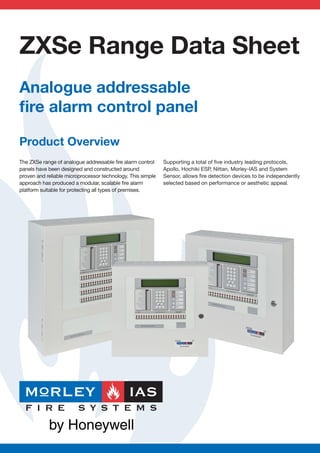
fire alarm control panel
Product Overview
The ZXSe range of analogue addressable fire alarm control Supporting a total of five industry leading protocols,
panels have been designed and constructed around Apollo, Hochiki ESP, Nittan, Morley-IAS and System
proven and reliable microprocessor technology. This simple Sensor, allows fire detection devices to be independently
approach has produced a modular, scalable fire alarm selected based on performance or aesthetic appeal.
platform suitable for protecting all types of premises.
2. Panel Features Networking Features
The ZXSe range of intelligent fire alarm control panels The Morley-IAS network is a unique, robust protocol
has been designed to assist with the normal operation that can be used over long distances, and utilise many
of a fire detection system. Standard weekly testing is different types of fire resistant cabling. All versions of
available through a simple menu structure allowing the ZXSe range can be connected together creating a
selection of the zones to be tested either with or without network of up to 99 control panels. The flexible network
activation of the output relays or sounders. can be configured in two ways:
Additionally, the status of individual devices can be • Shared Zone System - Each networked control panel
analysed to determine whether cleaning or replacement shares information
is required. • Report & Control System - For multiple building sites
where information is presented at the local and master
As the installation grows the ZXSe panel can expand panels only
with the building or site by adding additional devices, • A compliant fault tolerant network can be created
loop cards, printers or repeater panels. Additionally, using the additional, optional Hi-485 network card
further ZXSe panels can be networked together allowing • 99 panel network allows systems in excess of 60,000
an even bigger system to be created. devices to be managed
Remote (or local) printers can easily be connected to
provide a paper copy of events as and when they occur or
provide a historical record.
User Interface
• All major device manufacturers devices supported
A quick glance enables users to assess the condition
• Optional, local or remote printers
of the fire alarm system. Alarm and Fault conditions
• Walk test facility
are highlighted by LEDs and supported by enhanced
• Provide up to 72hr stand-by (subject to verification)
text descriptions on the LCD display. Clearly labelled
buttons allow users to quickly manipulate the system
providing both audible and tactile feedback of successful
operations.
Software Features
The panel has 3 access levels. Level 1 is unprotected
The initial installation of the system is aided by and allows basic user functions. Level 2 is passcode
sophisticated features like AUTOLEARN. An internal protected and allows more advanced user functions.
routine that will automatically detect all the devices on Level 3 is protected by a different passcode and allows
the detection and peripheral loops saving valuable programming functions.
commissioning time.
• 4x40 – Character LCD alphanumeric display with
An off-line Windows™ configuration tool is included back-light
to further enhance the process, making text entry and • Up to 200 zone LEDs (by special request)
specific, complex device programming easier. Complex • Up to 10 individual level 2 user access codes
cause and effect programming is simplified through • Optional lockable glass door – provides added
a clearly designed user interface. Once completed security/protection
the configuration of the panel can be saved for future
reference. Enhanced features allow the complete
archiving of the control panel history log.
• Event logic – facilitates complex cross-panel
Key Features
programming
• Multi-protocol
• Auto-learn facility allows rapid and accurate
• Modular concept
commissioning of devices
• Simple, robust design to EN54 Parts 2 & 4
• Windows™ configuration tool allows off-site
• Intuitive to use
programming
• Easy to maintain
• Facility to print history and event logs
• Easy to expand
• Easy to network
• Easy to install
• Easy to configure
3. Hardware Features
ZX1Se ZX2Se ZX5Se
Zones 200 (max) 200 (max) 200 (max)
LED Type Zonal Indicators 20 20 20 (Up to 200 available
FIRE/FAULT/TEXT/DISABLED on special request)
Internal Sounder
User Controls Sound Alarms, Silence/Resound, Mute Buzzer, Accept, System Reset
Programming Controls Alphanumeric multi- Alphanumeric multi- Alphanumeric multi-
level keypad level keypad level keypad
LED Type General Panel FIRE, FAULT, Acknowledged, Disablement, Test, Sounder Fault,
Status Indicators Delayed Mode, Relays Disabled, Earth Fault, System/CPU Fault,
Sounders Disabled, Alarms Silenced, Supply Fault, Power
Serial Interface 2 serial ports with connections for optional RS485 or 3 serial ports with
RS232 plug-in communication cards connections for optional
RS485 or RS232 plug-in
communication cards
Auxiliary Relays 1 fault and 1 fire relay voltage free, changeover outputs EN54 format at 1 fault
contacts rated at 24V AC/DC, 1A, 0.6 PF maximum relay and 1 programmable
relay voltage free,
changeover outputs
contacts rated at 24V
AC/DC, 1A, 0.6 pF
maximum
Sounder Outputs 2 programmable outputs. Open and short circuit 4 Programmable outputs.
monitoring. 1A maximum per output Open and short circuit
(Maximum total load 1.3A) monitoring. 1A maximum
per output
(Maximum total load 1.3A)
Protocol Devices
Each panel is capable of supporting Apollo (Xplorer,
XP95 & Discovery), Hochiki ESP, Nittan, Morley-IAS and
System Sensor protocol devices.1
ZX1Se Loop Capacity: 1 loop 460mA maximum
ZX2Se Loop Capacity: 1 or 2 loops 460mA per loop
maximum
ZX5Se Loop Capacity: 1 to 5 loops 460mA per loop
maximum
Number Apollo Hochiki System Nittan Morley
of Protocol Protocol Sensor Protocol Protocol
Devices Protocol
126
198
4. ZXSe System Example
Graphical Active External
User Interface Master Repeater Printer
High-485
High Integrity
Network
ZX5Se
Passive
P i ZX1Se ZX1Se
Repeater
ZX2Se ZX2Se
ZX1Se ZX5Se ZX5Se
Sub-Master Sub-Master
ZX5Se
5. Mechanical ZX1Se ZX2Se ZX5Se
Dimensions (mm) 400 x 400 x 135 (H x W x D) 400 x 400 x 135 (H x W x D) 500 x 500 x 195 (H x W x D)
Weight (without batteries) 10 kg 10 kg 20 kg
Colour RAL 9002 - Grey White RAL 9002 - Grey White RAL 9002 - Grey White
Environmental Operating Limits:
Temperature 0ºC to + 40ºC 0ºC to + 40ºC 0ºC to + 40ºC
Humidity 85% non-condensing (max) 85% non-condensing (max) 85% non-condensing (max)
Construction Sheet steel painted, Sheet steel painted, Sheet steel painted,
sealed to IP30 sealed to IP30 sealed to IP30
Cable Entry 14 x 20mm knock-outs in top of cabinet 24 x 20mm knock-outs top
2 x 20mm knock-outs in bottom of cabinet 24 x 20mm knock-outs bottom
500 mm
400 mm
400 mm
195 mm
135 mm 135 mm
400 mm 400 mm 500 mm
* not drawn to scale
Electrical ZX1Se ZX2Se ZX5Se
Operating Voltage 230V AC 50Hz (+10%,-15%) 230V AC 50Hz (+10%,-15%) 230V AC 50Hz (+10%,-15%)
Maximum PSU Rating 4.2A total, comprised of 2.5A min @ 25V 8.6A total, comprised of
(panel and loop supply) 1.75A min charger current 2.25A min @ 25V (panel
supply) 2.5A min @
35V (loop supply) 1.66A
min @ 12V (printer supply)
2.2A min charger current
Loop Load 460mA maximum 460mA per loop maximum 460mA per loop maximum
Stand-by Batteries:
Minimum Capacity 2 x 12V 7Ah 2 x 12V 7Ah 2 x 12V 12Ah
Maximum Capacity 2 x 12V 12Ah 2 x 12V 12Ah 2 x 12V 24Ah
Panel Designed to Meet up to max 38Ah2 up to max 38Ah2 up to max 38Ah2&3
EN54-4 Charging
Requirements For Larger
Batteries if Required
Notes
1
Multiple sensor protocols cannot be used in the panel simultaneously. However, different panels on the same network can support different protocols
2
Separate battery box required
3
Please contact your local business manager if there is a requirement to charge batteries >38Ah