Chennai Call Gril 80022//12248 Only For Sex And High Profile Best Gril Sex Av...
0912 Mc Kew (2)
1. Maybe the problem was born in design — overestimating pump head, or a cooling tower that isn’t
towering enough. Or it arose in installation — say, misconnected coils. Even then, a fix may create
a new water mystery. Get in step with some successful detecting habits to correct the next
troubled system you see.
BY HOWARD MCKEW, P.E., CPE
T
roubleshooting building systems is a niche business that I know this works because when I designed the Massachusetts
is immune to the economy or building owner’s operating State Transportation Building chilled water system over 30 years
budgets. When an HVAC system doesn’t work, or doesn’t ago, I started with a system flow diagram and wrote the sequence as
want to work to the owner’s expectations, the results can be I sketched out the design.
disastrous. For health care institutions, a system shutdown At that time, I couldn’t ask anyone in the office, “Now, how did
could interrupt an operating room procedure. For an industrial we do this the last time?” This was a first of its kind, one-million-
facility, it could mean stopping product production. For an edu- sq-ft facility that could have been conventionally designed with
cational facility, it could mean IAQ problems. So what are some of 2,000 tons of peak chiller capacity but instead was designed with a
those problematic jobs, and how did they become problems? Here 600-ton chiller in series with two 300-ton chillers and three thermal
are some of experiences from 40-plus years in the building industry, storage tanks, each with a capacity of 275,000 gal for cooling that
focusing on central chilled water systems. would become thermal heating storage (no boiler or utility steam)
in the heating season.
HOW DO SYSTEM PROBLEMS START? I was confident the design would work. When the time came
I believe most problematic systems originate in the design phase of for the system to be commissioned (before the word commission-
a construction project, due to an inadequate design process. Every ing was coined), the process went smoothly as I worked with the
HVAC system design should start with a single-line flow diagram in automatic temperature control (ATC) and TAB contractors. Today,
the conceptual/schematic phase. computer-aided software has replaced paper and pencil for creating
At this early stage of the building program, the design engineer flow diagram sketches (refer to the “Back2Basics” series for 21st-
can write a sequence of operation even if the designer has not firmed century flow diagram technology), but the designer should still start
up the chilled water system capacity. Having thought through the with a system flow diagram.
design, sequence by sequence, the engineer is able follow the chilled I approach troubleshooting as if I were designing the chilled
water flow through the system, adding control devices as the written water system way back in the design phase. It is also important to
sequence is documented. note this same ATC flow diagram has a second application when
30 En gi n e e r e d S y stem s December 2009
2. Troubleshooting Chilled Water Sytems
CHWR
troubleshooting/assessing water balance.
Just like when I sketched out the ATC sys-
C tem flow diagrams as the design engineer,
1,000 feet (pipe & fittings) O Last coil
At 3 feet/100 = 30 feet I 10 ft I would copy the diagram and re-use it
L to begin plugging in the pressure drops
ATC valve
throughout the system to come up with my
10 ft total chilled water pump head. Figure 1 is a
Chiller computer software version of this concept
and a document that can be forwarded
70 ft Chiller onto the TAB firm in the construction
Pumphead 20 ft phase. Armed with these two troubleshoot-
ing tools, the ATC flow diagram and a TAB
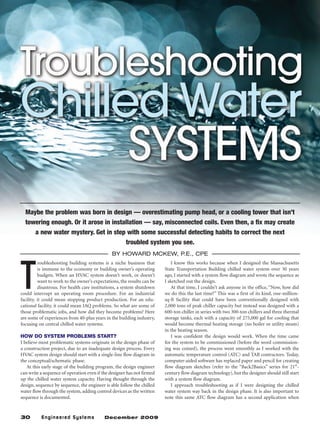
FIGURE 1. Budget estimating pump head. flow diagram, I’m ready to begin trouble-
shooting.
Open cooling tower DON’T UNDERESTIMATE THE
CONSEQUENCES OF
OVERESTIMATION
Next to not using a system ATC flow diagram
2-ft pressure drop Tower sump in the design phase, the most common issue
thru strainer water level to troubleshoot, which starts in the design
phase and ends up as an inefficient pumping
Condenser water pump
design, is caused by designers who overesti-
10 ft elevation mate the pump head. Frequently, designers
to provide 8 ft
think bigger is better, but more often than
}
NPSH at pump
Condenser inlet not, overdesign can lead to operational issues
water supply and increased energy consumption. A guide
to use when sizing a chilled water system is
to figure the total pump head will be around
60- to 70-ft pump head. When I see pumps
8 ft NPSH heads closing in at 100 ft — or worse yet, 200
per manufacturer’s
requirement ft — I’m pretty sure I will find a lot of balanc-
ing valves substantially closed or maybe just
one substantially closed balancing valve on
FIGURE 2. Cooling tower and pump installation net positive suction head (NPSH).
the pump discharge.
Some engineers will tell you it is better to
0 psig oversize pump heads in VFD systems and be
safe then to undersize and come up short on
In vacuum Positive pressure chilled water flow. That position is fine if the
design engineer is paying the extra money it
takes to furnish and install a 100-hp motor
(motor, starter, wiring, etc.) when a 75-hp
1/4-in. motor would do. I have had the opportunity
Tubing
to design some very large building HVAC sys-
Typical petcock
tems and re-engineer other very large systems
over the years, and I have never designed a
chilled water system over 125-ft pump head.
At the same time, I have retro-commissioned
Condenser water several chilled water systems that initially
from open
cooling tower ranged from 150 to 290 ft of pump head and
Condenser
water pump got them down under 125 ft without com-
promising chilled water performance. When
assessing these multiple central chilled water
Typical systems, I found them to be in the range of
shut-off valve 0.25 to 0.35 hp/ton, and got them to operate
Typical strainer under 0.1 hp/ton. A good troubleshooting
rule of thumb is 0.05 to 0.1 hp/ton.
FIGURE 3. Duplex strainer with compound gauge.
32 En gi n e e r e d S y stem s December 2009
3. When it has to be stainless,
it has to be A-J! Troubleshooting Chilled
Water Sytems
The experts in stainless
steel clean air systems
forwaste water 45˚F CHWS
treatment facilities,
plus:
• Custom fabrication
• Rush deliveries 80˚F Airflow Coil 55˚F
A-J Manufacturing offers a complete line of custom
and standard stainless steel air distribution products, all
designed and manufactured to offer durable, dependable
and low maintenance performance necessary for waste 55˚F CHWR
water treatment facilities.
Parallel flow – Wrong
What’s more, with our state-of-the-art manufacturing
capabilities, we can also offer you the industry’s shortest 55˚F CHWR
lead times for custom orders. So for continuous linear,
security grilles, modular diffusers and much more, contact
A-J Manufacturing today!
80˚F Airflow 55˚F
A-J Manufacturing Coil
800-247-5746 • www.ajmfg.com
Input 13 at www.esmagazine.com/instantproductinfo
45˚F CHWS
ES02084AJWasteWater.indd 1 12/13/07 2:37:23 PM
Counterflow – Correct
FIGURE 4. Right and wrong coil connections.
It’s what your
boiler would IS YOUR COOLING TOWER TALL ENOUGH?
A third troubleshooting problem that starts in the design phase is
choose... when the engineer fails to recognize the importance of open cooling
tower height in relationship to its condenser water pump. Centrifu-
Visit www.topog-e.com to learn gal pumps require a net positive suction head (NPSH) to ensure a
more about the world’s most minimal pressure on the inlet of the pump. In addition to minimal
popular molded rubber handhole inlet pressure, the designer needs to calculate the pressure loss from
resistance of the system via pipe friction loss, and, most importantly,
and manway gaskets. the pressure drop of the inlet strainer (Figure 2).
If the engineer does not position the open tower water sump sub-
Contact us to receive FREE: stantially above the pump inlet, the pump will operate in a vacuum
● STEAM TEMPERATURE SLIDE RULE
condition at its inlet. When troubleshooting this type of installa-
● TECHNICAL SPECIFICATION AND tion, my first recommendation is to raise the cooling tower, which
USAGE GUIDE probably won’t happen for a variety of existing conditions once the
● SAMPLE GASKET system has been installed.
● CONTACT DETAILS FOR YOUR LOCAL When stuck with this configuration as an existing condition, the
DISTRIBUTOR facility person can do a couple of things to alleviate some of the
operational problems. First, he can install two inlet strainers in par-
allel, so that the strainers can be cleaned on a regular basis without
For further information and a quotation:
shutting down the condenser water system.
1224 North Utica . Tulsa . Oklahoma 74110 The second suggestion is to install a compound gauge (Figure
(800) 587 7123
.
3, duplex strainer with compound gauge) which will read from
inches vacuum to zero to psig. This gauge should be manifolded to
tel 918 587 6649 fax 918 587 6961
sales@topog-e.com . www.topog-e.com be capable of reading before and after the strainer using the same
Input 36 at www.esmagazine.com/instantproductinfo
34 En gi n e e r e d S y stem s December 2009
ESM03071Topog-E.indd 1 2/19/07 10:39:02 AM
4. Troubleshooting Chilled
Water Sytems
gauge. Monitoring the gauge reading will allow the facility person
to switch from the dirty strainer to the clean strainer as the gauge
begins to show signs of the condenser water system pressure going
into a vacuum condition at the pump inlet.
INSTALLING THE PROBLEM
Troubleshooting problems don’t always originate in the design
phase and manifest themselves as full-blown calamities. Experience
has shown me this fourth issue occurs probably once out of every 25
chilled water coil installations: chilled water coil piped incorrectly
on the job site. The results is about a 20% inherent loss in coil cool-
ing capacity (Figure 4) when the chilled water supply is connected
on the upstream airside of the coil and the chilled water return con-
nection is piped to the downstream side of the coil.
Frequently, this problem goes undetected for years because the
coil was significantly oversized by the design engineer or the facil-
ity person came to (wrongly) accept that the coil was originally
undersized. I frequently find these misconnected coils when doing
a retro-commissioning assessment, but other times they are found
when troubleshooting why the cooling coil isn’t doing its job.
The same issue occurs with water-to-water heat exchangers that
do not have counter-flow between the condenser water and the
chilled water. Again, this deficiency may surface when troubleshoot-
ing the heat exchanger. On one occasion, we found the problem
while retro-commissioning a primary-secondary-tertiary pumping
system that was initially designed with 0.32 hp of pumping. We got
the pumping energy down below 0.1 hp/ton and re-piped the water-
to-water heat exchanger. You could say it was a win-win.
WHERE’D ALL THE WATER GO?
Occasionally, we will tune up chilled water systems by implement-
ing the corrective actions discussed herein, and when we do this, a
fifth problem occurs — namely, the “where is all this water going?”
dilemma. What I mean by this is that when rebalancing the system,
we cannot account for a percentage of the chilled water flow. When
this occurs, we find we need to be extra vigilant in documenting
piping supply and return connections along the chilled water dis-
tribution system.
In each case where the system was handling more water than
we could account for via flowmeters, we found unrecorded bypass
connections between the supply main and the return main. One
installation had a dozen unrecorded bypasses, while a second system
had ten. My only answer to these engineer-designed and unrecorded
bypasses is that they were probably installed to allow flushing of
segments of the pipe distribution during the construction phase
and, unfortunately, remained in operation after the owner took
occupancy. From a troubleshooting point of view, it is something
I look for now that I would not have thought to consider in the
past. I guess that is what is meant by the saying, “With age, comes
experience.”
A sixth troubleshooting challenge is when a second chiller plant
is furnished and installed within a facility to provide additional
cooling capacity because the existing chiller plant can’t handle the
load. In each case, the application was a health care institution, and
the need for additional air conditioning stemmed from the age of
the hospital dating back to the 1960s and 1970s, when some sections
of the hospital were not fully air conditioned.
36 En gi n e e r e d S y stem s December 2009
5. As each of these facilities received reno-
vations, upgrades, and building additions,
the new projects were fully air conditioned.
Often, the existing chilled water plant did
not have the space to accommodate future
equipment expansion, so a new location
was selected. The new chilled water system
was designed to handle the new addition
and/or renovations and was also tied into
the existing chilled water plant to work in
parallel. The results were less then success-
ful, and so I was contracted to trouble-
shoot each of these installations. Starting
with a flow diagram and surveying the
system distribution, the solution was the
same. The cross-connection of the sup-
ply of chiller plant 1 to chiller plant 2 was
done incorrectly (connected to the return
main by mistake). So after several years of
limited chiller plant performance, a solu-
tion was found.
SUMMARY
There are numerous installations that
mirror the few addressed herein, and I
Input 137 at www.esmagazine.com/instantproductinfo
truly believe if troubleshooters stick to the
basics of troubleshooting, solutions can be
achieved. As with any quality control pro-
cess, start with a flow diagram and begin
with data collection. Don’t simply jump to a
BREAKING NEWS !
conclusion without first analyzing the data;
consider the possibilities and then focus in
on the answer(s). ES NOW KLO-SHURE COUPLINGS
McKew is an inte-
grated project delivery
facilitator for the IPD
CAN SECURE 1/2"
INSULATION!
1
Group, RDK Engi-
neers (Andover, MA).
Reach him by e-mail
NO ONE ELSE
at hmckew@RDKen-
gineers.com.
MEASURES UP.
Meets 25/50 flame spread/smoke
developed index
Supports tubing and secures
3/8" – 1 1/2" insulation
Reduced material cost
Installs 60% faster – no tape, no glue
Superior vapor barrier
Eliminates insulation compression
No Call Backs
Contact us today to request your FREE product
catalog, and learn how well Klo-Shure Insulation
Couplings can work for your next project!
800.839.0891 www.klo-shure.com
Input 75 at www.esmagazine.com/instantproductinfo
w w w. esmag a zin e. co m 37
ESM05094Klo.indd 1 3/31/09 11:21:37 AM