Belt conveyor

The document discusses various components of belt conveyors including the belt construction, idlers, driving arrangements, tensioning, hold backs, and clearing devices. The belt construction section describes the main components of conveyor belts including the carcass, skims, and covers. It also discusses different types of belt materials like rubber and steel cord belts. The idlers section covers different types of carrying, impact, and return idlers. The driving arrangements section explains single unsunbbed drives, snubbed drives, tandem drives and special drives. Tensioning arrangements include manual screw take ups and automatic take ups. Hold backs are used to prevent reverse movement on inclined conveyors and can be low or high speed designs.

Recommended
More Related Content
What's hot
What's hot (20)
Viewers also liked
Viewers also liked (9)
Similar to Belt conveyor
Similar to Belt conveyor (20)
Recently uploaded
Recently uploaded (20)
Belt conveyor
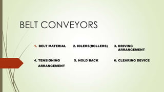
- 1. BELT CONVEYORS 1. BELT MATERIAL 2. IDLERS(ROLLERS) 3. DRIVING ARRANGEMENT 4. TENSIONING 5. HOLD BACK 6. CLEARING DEVICE ARRANGEMENT
- 2. INTRODUCTION A belt conveyor is rubber or textile structure with a belt shape closed ring, with a vulcanized or metallic joint, used for material transportation. Belt conveyors are the most used for transport of solid objects and bulk materials at great speed, covering great distances (up to 30 km)
- 3. BELT CONSTRUCTION Conveyor belts generally are composed of three main components: 1. Carcass 2. Skims 3. Covers There are two types of belt available: 1. Rubber belt 2. Steel Cord
- 5. 1. CARCASS The reinforcement usually found on the inside of a conveyor belt is normally referred to as the “carcass.” In a sense, the carcass is in the conveyor belt since it must: 1. Provide the tensile strength necessary to move the loaded belt. 2. Absorb the impact of the impinging material being loaded onto the conveyor belt. 3. Provide the bulk and lateral stiffness required for the load support.
- 7. The most common carcass design is made up of layers or “plies” of woven fabrics bonded together. This “conventional plied” belt construction, generally employs a plain weave or twill weave carcass which is built up into as many layers as is required to provide the necessary belt strength…usually bound together with rubber. Conventional plied belting constructions, employing all synthetic carcasses and elastomer covers appropriate to the end use, are particularly recommended for: I. Hard Rock Mining (A) Aggregate, sand and ore II. General purpose applications III. Forest products IV. Soft Minerals (A) Coal (B) Potash, Phosphates (C) Grain V. Unit Handling (A) Parcels (B) Baggage (C) Mail
- 8. The strength of fabric and the number of plies in the carcass of the belt may be varied together to suit the strength requirement. However if the belt is too tough, troughing of the belt and bending it round the terminal pulleys will be very difficult. Therefore the belt with lesser number of plies with stronger fabric is generally preferred because it is more flexible. Steel cord belting is used when good trough ability, small specific elongation and higher operating tensile forces are required. PVC belting is generally selected for underground mining applications where fire hazard exists.
- 9. 2. Skims The rubber, PVC or urethane between plies is called a “skim.” Skims are important contributors to internal belt adhesions, impact resistance, and play a significant role in determining belt “load support” and “troughability.” Improper or marginal “skims” can adversely affect belt performance in general and can lead to ply separation and/or idler junction failure.
- 10. 3. COVERS Covers are used in conveyor belt constructions in order to protect the base conveyor belt carcass and, if possible, to extend its service life. In addition, covers do provide the finished belt with a wide variety of desirable properties, including the following: A. Textures To increase friction To increase inclination To control product B. Cleanability C. A specific coefficient of friction D. A specific color E. Cut resistance F. Enhanced impact resistance, etc. G. Hardness H. Fire Resistance, Oil & Chemical Resistance
- 14. In addition to selecting proper compounds for cover material, it is also necessary to determine the proper cover thickness. The thickness of a cover is influenced by the amount of abuse and wear the belt will receive. The cover is usually the lowest cost component of the belt. The severity of the wear depends on the nature of the material and on the size, weight, shape and trip rate of the Material conveyed. Sharp edges, particularly on large pieces, can quickly cut a cover badly. On the other hand, if loading conditions are ideal, with the material being loaded in the direction of travel of the belt, and with only a slight impact onto the belt, even very sharp material may not seriously cut or wear the belt surface.
- 16. IDLERS (ROLLERS)
- 19. TYPES OF IDLERS TYPES OF CARRYING IDLERS
- 20. TYPES OF IMPACT IDLERS (OPTIONAL)
- 23. Types and Selection of Drives: Single Unsnubbed Bare / Lagged pulley Drive Snubbed Bare / Lagged Pulley Drive Tandem Drive Special Drives
- 24. Single Unsnubbed Bare / Lagged Pulley Drive: This is the simplest drive arrangement consisting of a steel pulley connected to a motor and the belt wrapped round it on an arc of 180°. This can be used for low capacity short center conveyors handling non-abrasive material. The pulley may be lagged to increase the coefficient of friction.
- 25. Snubbed Bare / Lagged Pulley Drive: Here the angle of wrap is increased from 180° to 210° or even up to 230°, by providing a snub pulley to the driving pulley. In majority of medium to large capacity belt conveyors, handling mild abrasive to fairly abrasive materials, 210° snub pulley drive with load pulley lagged with hard rubber is adopted.
- 26. Tandem drive: Here belt tension estimated to be high; the angle of wrap is increased by adopting tandem drives. Both of tandem pulleys are driven. The tandem drive with arc of contact from 300° to 480° or more can operate with one or two motors. The location of such drive is usually determined by the physical requirements of the plant and structural constraints.
- 27. Special Drive: Special drives with snub pulleys and pressure belts used in heavy and long conveyors.
- 28. TENSIONING ARRANGEMENT All belt conveyors require the use of some form of take up device (Tensioning Arrangement) for the following reasons: 1. To ensure adequate tension of the belt leaving the drive pulley so us to avoid any slippage of the belt. 2. To ensure proper belt tension at the loading and other points along the conveyor. 3. To compensate for changes in belt length due to elongation. 4. To provide extra length of belt when necessary for splicing purpose. Usually there are two types of take up arrangements. 1.Fixed take up device that may be adjusted periodically by manual operation 2.Automatic take up devices for constant load type
- 29. Manual Screw Take Up: The most commonly used manual take up is the screw take up. In a screw take up system the take up pulley rotates in two bearing blocks which may slide on stationery guide ways with the help of two screws. The tension is created by the two screws which are tightened and periodically adjusted with a spanner. It is preferable to use screws with trapezoidal thread to decrease the effort required to tighten the belt. DISADVANTAGE The main problem with the use of manual take up is that it requires a vigilant and careful operator to observe when take up adjustment is required. Perfect tension adjustment with this system is also not possible. For these reason these devices are used only in case of short conveyors of up 60m length and light duty.
- 31. Automatic Take Up: In automatic take up arrangement the take up pulley is mounted on slides or on a trolley which is pulled backwards by means of a steel rope and deflecting pulleys. The carriage travels on guide ways mounted parallel to the longitudinal axis of the conveyor, i.e., horizontally in horizontal conveyors (Ex.: Gravity type automatic take up arrangement) and at an incline in inclined conveyors. Hydraulic, Pneumatic and electrical take up devices are also used
- 34. HOLD BACK Inclined conveyors require an anti-runback device to prevent reverse movement of the belts. Such a device is referred to as a backstop, or holdback. Though backstops are most likely to be found on inclined conveyors, they are also employed on flat, overland conveyors to avoid the unusually severe shock loading on start-up where the loaded belt sags between idlers. This paper will direct its attention to backstops installed on inclined conveyors. Without a backstop, a reversing conveyor can rapidly accelerate to a runaway condition, which can kill or injure personnel, damage or destroy drive train components, tear or rip expensive belting, or cause considerable other damage.
- 35. Without a backstop, a reversing conveyor can rapidly accelerate to a runaway condition, which can kill or injure personnel, damage or destroy drive train components, tear or rip expensive belting, or cause considerable other damage. A backstop is essentially a safety device which acts to prevent reversal thereby protecting against any of the above from occurring, as well as the massive clean up of material spillage than can occur. Backstops can be classified either for : i) low-speed ii) high-speed use.
- 36. LOW-SPEED BACKSTOP DESIGN TYPES There are three basic backstop designs that are or have been used to prevent anti-runback throughout the many years of conveying materials; 1.rachet and pawl 2.differential handbrake and 3.the overrunning clutch design