SlideShare a Scribd company logo
1 of 62
Download to read offline
Large changes in tension can occur when a line is wrapped around a fixed cylinder.
© STOCK4B-RoyaltyFree/Image Source
335
6/1 Introduction
Section A Frictional Phenomena
6/2 Types of Friction
6/3 Dry Friction
Section B Applications of Friction in Machines
6/4 Wedges
6/5 Screws
6/6 Journal Bearings
6/7 Thrust Bearings; Disk Friction
6/8 Flexible Belts
6/9 Rolling Resistance
6/10 Chapter Review
CHAPTER OUTLINE
6Friction
6/1 Introduction
In the preceding chapters we have usually assumed that the forces
of action and reaction between contacting surfaces act normal to the
surfaces. This assumption characterizes the interaction between smooth
surfaces and was illustrated in Example 2 of Fig. 3/1. Although this
ideal assumption often involves only a relatively small error, there are
many problems in which we must consider the ability of contacting sur-
faces to support tangential as well as normal forces. Tangential forces
generated between contacting surfaces are called friction forces and
occur to some degree in the interaction between all real surfaces. When-
ever a tendency exists for one contacting surface to slide along another
surface, the friction forces developed are always in a direction to oppose
this tendency.
In some types of machines and processes we want to minimize the
retarding effect of friction forces. Examples are bearings of all types,
power screws, gears, the flow of fluids in pipes, and the propulsion of
aircraft and missiles through the atmosphere. In other situations we
wish to maximize the effects of friction, as in brakes, clutches, belt
drives, and wedges. Wheeled vehicles depend on friction for both start-
ing and stopping, and ordinary walking depends on friction between the
shoe and the ground.
Friction forces are present throughout nature and exist in all ma-
chines no matter how accurately constructed or carefully lubricated. A
machine or process in which friction is small enough to be neglected is
said to be ideal. When friction must be taken into account, the machine
or process is termed real. In all cases where there is sliding motion be-
tween parts, the friction forces result in a loss of energy which is dissi-
pated in the form of heat. Wear is another effect of friction.
SECTION A FRICTIONAL PHENOMENA
6/2 Types of Friction
In this article we briefly discuss the types of frictional resistance en-
countered in mechanics. The next article contains a more detailed ac-
count of the most common type of friction, dry friction.
(a) Dry Friction. Dry friction occurs when the unlubricated surfaces
of two solids are in contact under a condition of sliding or a tendency to
slide. A friction force tangent to the surfaces of contact occurs both dur-
ing the interval leading up to impending slippage and while slippage
takes place. The direction of this friction force always opposes the mo-
tion or impending motion. This type of friction is also called Coulomb
friction. The principles of dry or Coulomb friction were developed
largely from the experiments of Coulomb in 1781 and from the work of
Morin from 1831 to 1834. Although we do not yet have a comprehensive
theory of dry friction, in Art. 6/3 we describe an analytical model suffi-
cient to handle the vast majority of problems involving dry friction. This
model forms the basis for most of this chapter.
(b) Fluid Friction. Fluid friction occurs when adjacent layers in a
fluid (liquid or gas) are moving at different velocities. This motion
causes frictional forces between fluid elements, and these forces depend
on the relative velocity between layers. When there is no relative veloc-
ity, there is no fluid friction. Fluid friction depends not only on the ve-
locity gradients within the fluid but also on the viscosity of the fluid,
which is a measure of its resistance to shearing action between fluid lay-
ers. Fluid friction is treated in the study of fluid mechanics and will not
be discussed further in this book.
(c) Internal Friction. Internal friction occurs in all solid materials
which are subjected to cyclical loading. For highly elastic materials the
recovery from deformation occurs with very little loss of energy due to
internal friction. For materials which have low limits of elasticity and
which undergo appreciable plastic deformation during loading, a consid-
erable amount of internal friction may accompany this deformation.
The mechanism of internal friction is associated with the action of shear
deformation, which is discussed in references on materials science. Be-
cause this book deals primarily with the external effects of forces, we
will not discuss internal friction further.
336 Chapter 6 Friction
6/3 Dry Friction
The remainder of this chapter describes the effects of dry friction
acting on the exterior surfaces of rigid bodies. We will now explain the
mechanism of dry friction with the aid of a very simple experiment.
Mechanism of Dry Friction
Consider a solid block of mass m resting on a horizontal surface, as
shown in Fig. 6/1a. We assume that the contacting surfaces have some
roughness. The experiment involves the application of a horizontal force
P which continuously increases from zero to a value sufficient to move
the block and give it an appreciable velocity. The free-body diagram of
the block for any value of P is shown in Fig. 6/1b, where the tangential
friction force exerted by the plane on the block is labeled F. This friction
force acting on the body will always be in a direction to oppose motion
or the tendency toward motion of the body. There is also a normal force
N which in this case equals mg, and the total force R exerted by the sup-
porting surface on the block is the resultant of N and F.
A magnified view of the irregularities of the mating surfaces, Fig.
6/1c, helps us to visualize the mechanical action of friction. Support is
necessarily intermittent and exists at the mating humps. The direction
of each of the reactions on the block, R1, R2, R3, etc. depends not only on
the geometric profile of the irregularities but also on the extent of local
deformation at each contact point. The total normal force N is the sum
Article 6/3 Dry Friction 337
Pm P
F
α
RN
mg
(a)
(c)
t
n
F
F
=
P
Fmax = s Nμ Fk = k Nμ
R1
R3R2
(b)
P
Static
friction
(no motion)
Kinetic
friction
(motion)
Impending
motion
(d)
Figure 6/1
of the n-components of the R’s, and the total frictional force F is the
sum of the t-components of the R’s. When the surfaces are in relative
motion, the contacts are more nearly along the tops of the humps, and
the t-components of the R’s are smaller than when the surfaces are at
rest relative to one another. This observation helps to explain the well-
known fact that the force P necessary to maintain motion is generally
less than that required to start the block when the irregularities are
more nearly in mesh.
If we perform the experiment and record the friction force F as a
function of P, we obtain the relation shown in Fig. 6/1d. When P is
zero, equilibrium requires that there be no friction force. As P is in-
creased, the friction force must be equal and opposite to P as long as
the block does not slip. During this period the block is in equilibrium,
and all forces acting on the block must satisfy the equilibrium equa-
tions. Finally, we reach a value of P which causes the block to slip and
to move in the direction of the applied force. At this same time the
friction force decreases slightly and abruptly. It then remains essen-
tially constant for a time but then decreases still more as the velocity
increases.
Static Friction
The region in Fig. 6/1d up to the point of slippage or impending mo-
tion is called the range of static friction, and in this range the value of
the friction force is determined by the equations of equilibrium. This
friction force may have any value from zero up to and including the
maximum value. For a given pair of mating surfaces the experiment
shows that this maximum value of static friction Fmax is proportional to
the normal force N. Thus, we may write
(6/1)
where ␮s is the proportionality constant, called the coefficient of static
friction.
Be aware that Eq. 6/1 describes only the limiting or maximum value
of the static friction force and not any lesser value. Thus, the equation
applies only to cases where motion is impending with the friction force
at its peak value. For a condition of static equilibrium when motion is
not impending, the static friction force is
Kinetic Friction
After slippage occurs, a condition of kinetic friction accompanies the
ensuing motion. Kinetic friction force is usually somewhat less than the
maximum static friction force. The kinetic friction force Fk is also pro-
portional to the normal force. Thus,
(6/2)Fk ϭ ␮kN
F Ͻ ␮s N
Fmax ϭ ␮s N
338 Chapter 6 Friction
where ␮k is the coefficient of kinetic friction. It follows that ␮k is gener-
ally less than ␮s. As the velocity of the block increases, the kinetic fric-
tion decreases somewhat, and at high velocities, this decrease may be
significant. Coefficients of friction depend greatly on the exact condition
of the surfaces, as well as on the relative velocity, and are subject to con-
siderable uncertainty.
Because of the variability of the conditions governing the action of
friction, in engineering practice it is frequently difficult to distinguish
between a static and a kinetic coefficient, especially in the region of
transition between impending motion and motion. Well-greased screw
threads under mild loads, for example, often exhibit comparable fric-
tional resistance whether they are on the verge of turning or whether
they are in motion.
In the engineering literature we frequently find expressions for max-
imum static friction and for kinetic friction written simply as F ϭ ␮N. It
is understood from the problem at hand whether maximum static fric-
tion or kinetic friction is described. Although we will frequently distin-
guish between the static and kinetic coefficients, in other cases no
distinction will be made, and the friction coefficient will be written
simply as ␮. In those cases you must decide which of the friction condi-
tions, maximum static friction for impending motion or kinetic fric-
tion, is involved. We emphasize again that many problems involve a
static friction force which is less than the maximum value at impend-
ing motion, and therefore under these conditions the friction relation
Eq. 6/1 cannot be used.
Figure 6/1c shows that rough surfaces are more likely to have
larger angles between the reactions and the n-direction than are
smoother surfaces. Thus, for a pair of mating surfaces, a friction coef-
ficient reflects the roughness, which is a geometric property of the
surfaces. With this geometric model of friction, we describe mating
surfaces as “smooth” when the friction forces they can support are
negligibly small. It is meaningless to speak of a coefficient of friction
for a single surface.
Friction Angles
The direction of the resultant R in Fig. 6/1b measured from the
direction of N is specified by tan ␣ ϭ F/N. When the friction force
reaches its limiting static value Fmax, the angle ␣ reaches a maximum
value ␾s. Thus,
When slippage is occurring, the angle ␣ has a value ␾k corresponding to
the kinetic friction force. In like manner,
In practice we often see the expression tan ␾ ϭ ␮, in which the
coefficient of friction may refer to either the static or the kinetic case,
tan ␾k ϭ ␮k
tan ␾s ϭ ␮s
Article 6/3 Dry Friction 339
This tree surgeon depends on the
friction between the rope and the
mechanical devices through which
the rope can slip.
©BlackoutConcepts/Stockphotopro,Inc
depending on the particular problem. The angle ␾s is called the angle of
static friction, and the angle ␾k is called the angle of kinetic friction. The
friction angle for each case clearly defines the limiting direction of the
total reaction R between two contacting surfaces. If motion is impend-
ing, R must be one element of a right-circular cone of vertex angle 2␾s,
as shown in Fig. 6/2. If motion is not impending, R is within the cone.
This cone of vertex angle 2␾s is called the cone of static friction and rep-
resents the locus of possible directions for the reaction R at impending
motion. If motion occurs, the angle of kinetic friction applies, and the
reaction must lie on the surface of a slightly different cone of vertex
angle 2␾k. This cone is the cone of kinetic friction.
Factors Affecting Friction
Further experiment shows that the friction force is essentially in-
dependent of the apparent or projected area of contact. The true con-
tact area is much smaller than the projected value, since only the peaks
of the contacting surface irregularities support the load. Even rela-
tively small normal loads result in high stresses at these contact points.
As the normal force increases, the true contact area also increases as
the material undergoes yielding, crushing, or tearing at the points of
contact.
A comprehensive theory of dry friction must go beyond the mechan-
ical explanation presented here. For example, there is evidence that
molecular attraction may be an important cause of friction under condi-
tions where the mating surfaces are in very close contact. Other factors
which influence dry friction are the generation of high local tempera-
tures and adhesion at contact points, relative hardness of mating sur-
faces, and the presence of thin surface films of oxide, oil, dirt, or other
substances.
Some typical values of coefficients of friction are given in Table D/1,
Appendix D. These values are only approximate and are subject to con-
siderable variation, depending on the exact conditions prevailing. They
may be used, however, as typical examples of the magnitudes of fric-
tional effects. To make a reliable calculation involving friction, the
appropriate friction coefficient should be determined by experiments
which duplicate the surface conditions of the application as closely as
possible.
340 Chapter 6 Friction
Cone of
static friction
2 kφ
2 sφ
Cone of
kinetic friction
R
Figure 6/2
Article 6/3 Dry Friction 341
Types of Friction Problems
We can now recognize the following three types of problems encoun-
tered in applications involving dry friction. The first step in solving a
friction problem is to identify its type.
1. In the first type of problem, the condition of impending motion is
known to exist. Here a body which is in equilibrium is on the verge
of slipping, and the friction force equals the limiting static friction
Fmax ϭ ␮sN. The equations of equilibrium will, of course, also hold.
2. In the second type of problem, neither the condition of impending
motion nor the condition of motion is known to exist. To determine
the actual friction conditions, we first assume static equilibrium and
then solve for the friction force F necessary for equilibrium. Three
outcomes are possible:
(a) F Ͻ (Fmax ϭ ␮sN): Here the friction force necessary for
equilibrium can be supported, and therefore the body is in
static equilibrium as assumed. We emphasize that the actual
friction force F is less than the limiting value Fmax given by
Eq. 6/1 and that F is determined solely by the equations of
equilibrium.
(b) F ϭ (Fmax ϭ ␮sN): Since the friction force F is at its maximum
value Fmax, motion impends, as discussed in problem type (1).
The assumption of static equilibrium is valid.
(c) F Ͼ (Fmax ϭ ␮sN): Clearly this condition is impossible, because
the surfaces cannot support more force than the maximum ␮sN.
The assumption of equilibrium is therefore invalid, and motion
occurs. The friction force F is equal to ␮kN from Eq. 6/2.
3. In the third type of problem, relative motion is known to exist
between the contacting surfaces, and thus the kinetic coefficient of
friction clearly applies. For this problem type, Eq. 6/2 always gives
the kinetic friction force directly.
KEY CONCEPTS
The foregoing discussion applies to all dry contacting surfaces and,
to a limited extent, to moving surfaces which are partially lubricated.
SAMPLE PROBLEM 6/1
Determine the maximum angle ␪ which the adjustable incline may have
with the horizontal before the block of mass m begins to slip. The coefficient of
static friction between the block and the inclined surface is ␮s.
Solution. The free-body diagram of the block shows its weight W ϭ mg, the
normal force N, and the friction force F exerted by the incline on the block. The
friction force acts in the direction to oppose the slipping which would occur if no
friction were present.
Equilibrium in the x- and y-directions requires
Dividing the first equation by the second gives F/N ϭ tan ␪. Since the maximum
angle occurs when F ϭ Fmax ϭ ␮sN, for impending motion we have
Ans.
SAMPLE PROBLEM 6/2
Determine the range of values which the mass m0 may have so that the 100-kg
block shown in the figure will neither start moving up the plane nor slip down
the plane. The coefficient of static friction for the contact surfaces is 0.30.
Solution. The maximum value of m0 will be given by the requirement for mo-
tion impending up the plane. The friction force on the block therefore acts down
the plane, as shown in the free-body diagram of the block for Case I in the figure.
With the weight mg ϭ 100(9.81) ϭ 981 N, the equations of equilibrium give
Ans.
The minimum value of m0 is determined when motion is impending down the
plane. The friction force on the block will act up the plane to oppose the ten-
dency to move, as shown in the free-body diagram for Case II. Equilibrium in the
x-direction requires
Ans.
Thus, m0 may have any value from 6.01 to 62.4 kg, and the block will remain at
rest.
In both cases equilibrium requires that the resultant of Fmax and N be con-
current with the 981-N weight and the tension T.
m0(9.81) ϩ 277 Ϫ 981 sin 20Њ ϭ 0 m0 ϭ 6.01 kg[ΣFx ϭ 0]
m0(9.81) Ϫ 277 Ϫ 981 sin 20Њ ϭ 0 m0 ϭ 62.4 kg[ΣFx ϭ 0]
Fmax ϭ 0.30(922) ϭ 277 N[Fmax ϭ ␮s N]
N Ϫ 981 cos 20Њ ϭ 0 N ϭ 922 N[ΣFy ϭ 0]
␮s ϭ tan ␪max or ␪max ϭ tanϪ1 ␮s
Ϫmg cos ␪ ϩ N ϭ 0 N ϭ mg cos ␪[ΣFy ϭ 0]
mg sin ␪ Ϫ F ϭ 0 F ϭ mg sin ␪[ΣFx ϭ 0]
342 Chapter 6 Friction
m
θ
sμ
x
y
F N
W = mg
θ
20° m0
100 kg
20°
981 N
N
Case I
x
y
Fmax
Fmax
T = m0 g
20°
981 N
N
Case II
x
y
T = m0 g
ᕡ
ᕢ
ᕡ
Helpful Hints
ᕡ We choose reference axes along and
normal to the direction of F to
avoid resolving both F and N into
components.
ᕢ This problem describes a very simple
way to determine a static coefficient
of friction. The maximum value of ␪
is known as the angle of repose.
Helpful Hint
ᕡ We see from the results of Sample
Problem 6/1 that the block would
slide down the incline without the re-
straint of attachment to m0 since tan
20Њ Ͼ 0.30. Thus, a value of m0 will
be required to maintain equilibrium.
SAMPLE PROBLEM 6/3
Determine the magnitude and direction of the friction force acting on the
100-kg block shown if, first, P ϭ 500 N and, second, P ϭ 100 N. The coefficient of
static friction is 0.20, and the coefficient of kinetic friction is 0.17. The forces are
applied with the block initially at rest.
Solution. There is no way of telling from the statement of the problem whether
the block will remain in equilibrium or whether it will begin to slip following the
application of P. It is therefore necessary that we make an assumption, so we will
take the friction force to be up the plane, as shown by the solid arrow. From the
free-body diagram a balance of forces in both x- and y-directions gives
Case I. P ϭ 500 N
Substitution into the first of the two equations gives
The negative sign tells us that if the block is in equilibrium, the friction force
acting on it is in the direction opposite to that assumed and therefore is down
the plane, as represented by the dashed arrow. We cannot reach a conclusion on
the magnitude of F, however, until we verify that the surfaces are capable of
supporting 134.3 N of friction force. This may be done by substituting P ϭ 500 N
into the second equation, which gives
The maximum static friction force which the surfaces can support is then
Since this force is greater than that required for equilibrium, we conclude that
the assumption of equilibrium was correct. The answer is, then,
Ans.
Case II. P ϭ 100 N
Substitution into the two equilibrium equations gives
But the maximum possible static friction force is
It follows that 242 N of friction cannot be supported. Therefore, equilibrium cannot
exist, and we obtain the correct value of the friction force by using the kinetic coeffi-
cient of friction accompanying the motion down the plane. Hence, the answer is
Ans.F ϭ 0.17(956) ϭ 162.5 N up the plane[Fk ϭ ␮k N]
Fmax ϭ 0.20(956) ϭ 191.2 N[Fmax ϭ ␮s N]
F ϭ 242 N N ϭ 956 N
F ϭ 134.3 N down the plane
Fmax ϭ 0.20(1093) ϭ 219 N[Fmax ϭ ␮s N]
N ϭ 1093 N
F ϭ Ϫ134.3 N
N Ϫ P sin 20Њ Ϫ 981 cos 20Њ ϭ 0[ΣFy ϭ 0]
P cos 20Њ ϩ F Ϫ 981 sin 20Њ ϭ 0[ΣFx ϭ 0]
Article 6/3 Dry Friction 343
20°
P 100 kg
20°
100(9.81) = 981 N
P
N
F
x
y
F
ᕡ
Helpful Hint
ᕡ We should note that even though ΣFx
is no longer equal to zero, equilibrium
does exist in the y-direction, so that
ΣFy ϭ 0. Therefore, the normal force
N is 956 N whether or not the block is
in equilibrium.
SAMPLE PROBLEM 6/4
The homogeneous rectangular block of mass m, width b, and height H is
placed on the horizontal surface and subjected to a horizontal force P which
moves the block along the surface with a constant velocity. The coefficient of ki-
netic friction between the block and the surface is ␮k. Determine (a) the greatest
value which h may have so that the block will slide without tipping over and
(b) the location of a point C on the bottom face of the block through which the
resultant of the friction and normal forces acts if h ϭ H/2.
Solution. (a) With the block on the verge of tipping, we see that the entire re-
action between the plane and the block will necessarily be at A. The free-body
diagram of the block shows this condition. Since slipping occurs, the friction
force is the limiting value ␮kN, and the angle ␪ becomes ␪ ϭ tanϪ1
␮k. The resul-
tant of Fk and N passes through a point B through which P must also pass, since
three coplanar forces in equilibrium are concurrent. Hence, from the geometry
of the block
Ans.
If h were greater than this value, moment equilibrium about A would not be
satisfied, and the block would tip over.
Alternatively, we may find h by combining the equilibrium requirements for
the x- and y-directions with the moment-equilibrium equation about A. Thus,
Ans.
(b) With h ϭ H/2 we see from the free-body diagram for case (b) that the re-
sultant of Fk and N passes through a point C which is a distance x to the left of
the vertical centerline through G. The angle ␪ is still ␪ ϭ ␾ ϭ tanϪ1
␮k as long as
the block is slipping. Thus, from the geometry of the figure we have
Ans.
If we were to replace ␮k by the static coefficient ␮s, then our solutions would
describe the conditions under which the block is (a) on the verge of tipping and
(b) on the verge of slipping, both from a rest position.
x
H/2
ϭ tan ␪ ϭ ␮k so x ϭ ␮k H/2
Ph Ϫ mg
b
2
ϭ 0 h ϭ
mgb
2P
ϭ
mgb
2␮kmg
ϭ
b
2␮k
[ΣMA ϭ 0]
Fk Ϫ P ϭ 0 P ϭ Fk ϭ ␮k N ϭ ␮kmg[ΣFx ϭ 0]
N Ϫ mg ϭ 0 N ϭ mg[ΣFy ϭ 0]
tan ␪ ϭ ␮k ϭ
b/2
h
h ϭ
b
2␮k
344 Chapter 6 Friction
P
m
b
H
h
P
G
mg
θ
θ
x
y
B
A
N
Fk
h
b
—
2
P
G
mg
θ
θ
C
N
xFk
H
—
2
ᕡ
ᕢ
Helpful Hints
ᕡ Recall that the equilibrium equa-
tions apply to a body moving with a
constant velocity (zero acceleration)
just as well as to a body at rest.
ᕢ Alternatively, we could equate the
moments about G to zero, which
would give us F(H/2) Ϫ Nx ϭ 0. Thus,
with Fk ϭ ␮kN we get x ϭ ␮xH/2.
SAMPLE PROBLEM 6/5
The three flat blocks are positioned on the 30Њ incline as shown, and a force
P parallel to the incline is applied to the middle block. The upper block is pre-
vented from moving by a wire which attaches it to the fixed support. The coeffi-
cient of static friction for each of the three pairs of mating surfaces is shown.
Determine the maximum value which P may have before any slipping takes
place.
Solution. The free-body diagram of each block is drawn. The friction forces
are assigned in the directions to oppose the relative motion which would occur if
no friction were present. There are two possible conditions for impending mo-
tion. Either the 50-kg block slips and the 40-kg block remains in place, or the 50-
and 40-kg blocks move together with slipping occurring between the 40-kg block
and the incline.
The normal forces, which are in the y-direction, may be determined without
reference to the friction forces, which are all in the x-direction. Thus,
We will assume arbitrarily that only the 50-kg block slips, so that the 40-kg
block remains in place. Thus, for impending slippage at both surfaces of the
50-kg block, we have
The assumed equilibrium of forces at impending motion for the 50-kg block
gives
We now check on the validity of our initial assumption. For the 40-kg block
with F2 ϭ 272 N the friction force F3 would be given by
But the maximum possible value of F3 is F3 ϭ ␮sN3 ϭ 0.45(1019) ϭ 459 N. Thus,
468 N cannot be supported and our initial assumption was wrong. We conclude,
therefore, that slipping occurs first between the 40-kg block and the incline.
With the corrected value F3 ϭ 459 N, equilibrium of the 40-kg block for its im-
pending motion requires
Equilibrium of the 50-kg block gives, finally,
Ans.
Thus, with P ϭ 93.8 N, motion impends for the 50-kg and 40-kg blocks as a unit.
P ϭ 93.8 N
P ϩ 50(9.81) sin 30Њ Ϫ 263 Ϫ 76.5 ϭ 0[ΣFx ϭ 0]
F2 ϩ 40(9.81) sin 30Њ Ϫ 459 ϭ 0 F2 ϭ 263 N[ΣFx ϭ 0]
272 ϩ 40(9.81) sin 30Њ Ϫ F3 ϭ 0 F3 ϭ 468 N[ΣFx ϭ 0]
P Ϫ 76.5 Ϫ 272 ϩ 50(9.81) sin 30Њ ϭ 0 P ϭ 103.1 N[ΣFx ϭ 0]
F1 ϭ 0.30(255) ϭ 76.5 N F2 ϭ 0.40(680) ϭ 272 N[Fmax ϭ ␮s N]
(40-kg) N3 Ϫ 40(9.81) cos 30Њ Ϫ 680 ϭ 0 N3 ϭ 1019 N
(50-kg) N2 Ϫ 50(9.81) cos 30Њ Ϫ 255 ϭ 0 N2 ϭ 680 N
(30-kg) N1 Ϫ 30(9.81) cos 30Њ ϭ 0 N1 ϭ 255 N[ΣFy ϭ 0]
Article 6/3 Dry Friction 345
P
30 kg
s
= 0.30
μ
s
= 0.40
μ
50 kg
40 kg
30°
s
= 0.45
μ
30°
y
P
F1
F2
N2
N1
50(9.81) N
x
y
F1
T
N1
30(9.81) N
x
x
y
F2
F3
N3
N2
40(9.81) N
Helpful Hints
ᕡ In the absence of friction the middle
block, under the influence of P,
would have a greater movement
than the 40-kg block, and the fric-
tion force F2 will be in the direction
to oppose this motion as shown.
ᕢ We see now that F2 is less than
␮s N2 ϭ 272 N.
ᕢ
ᕡ
6/4 The coefficients of static and kinetic friction be-
tween the 100-kg block and the inclined plane are
0.30 and 0.20, respectively. Determine (a) the fric-
tion force F acting on the block when P is applied
with a magnitude of 200 N to the block at rest,
(b) the force P required to initiate motion up the in-
cline from rest, and (c) the friction force F acting on
the block if P = 600 N.
Problem 6/4
6/5 The magnitude of force P is slowly increased. Does
the homogeneous box of mass m slip or tip first?
State the value of P which would cause each occur-
rence. Neglect any effect of the size of the small
feet.
Problem 6/5
P
d
A
B C
2d
30°
s
= 0.50μ
m
20°
15°
100 kg
P
s = 0.30μ
k = 0.20μ
346 Chapter 6 Friction
PROBLEMS
Introductory Problems
6/1 The 85-lb force P is applied to the 200-lb crate,
which is stationary before the force is applied. De-
termine the magnitude and direction of the friction
force F exerted by the horizontal surface on the
crate.
Problem 6/1
6/2 The 700-N force is applied to the 100-kg block,
which is stationary before the force is applied. De-
termine the magnitude and direction of the friction
force F exerted by the horizontal surface on the
block.
Problem 6/2
6/3 The designer of a ski resort wishes to have a portion
of a beginner’s slope on which the skier’s speed will
remain fairly constant. Tests indicate the average
coefficients of friction between skis and snow to be
and . What should be the slope
angle of the constant-speed section?
Problem 6/3
θ
␪
␮k ϭ 0.08␮s ϭ 0.10
100 kg
30°
P = 700 N
s
= 0.80μ
k
= 0.60μ
P = 85 lb
200 lb
s
= 0.50μ
k
= 0.40μ
6/6 Determine the magnitude and direction of the fric-
tion force which the vertical wall exerts on the 100-lb
block if (a) and (b) .
Problem 6/6
6/7 Determine the minimum coefficient of static friction
which will allow the drum with fixed inner hub to
be rolled up the incline at a steady speed without
slipping. What are the corresponding values of the
force P and the friction force F?
Problem 6/7
6/8 The tongs are designed to handle hot steel tubes
which are being heat-treated in an oil bath. For a
jaw opening, what is the minimum coefficient
of static friction between the jaws and the tube
which will enable the tongs to grip the tube with-
out slipping?
20Њ
30°
P
15°
m
r
r/2 s
μ
15Њ
␮s
100 lb
P = 120 lb
s = 0.50
θ
μ
k = 0.40μ
␪ ϭ 30Њ␪ ϭ 15Њ
Article 6/3 Problems 347
Problem 6/8
6/9 The light bar is used to support the 50-kg block in
its vertical guides. If the coefficient of static fric-
tion is 0.30 at the upper end of the bar and 0.40 at
the lower end of the bar, find the friction force act-
ing at each end for x = 75 mm. Also find the maxi-
mum value of x for which the bar will not slip.
Problem 6/9
6/10 The semicircular 5-kg plate rotates about a fixed
bearing at O that can exert a maximum frictional
moment of 1.2 N m on the plate. The horizontal
force P is applied to a cord wrapped around the plate
periphery and pinned at A. (a) With P = 0, deter-
mine the maximum angle for which equilibrium
is possible. (b) From the position determined in
(a) calculate the force P required to rotate the body
counterclockwise.
Problem 6/10
P
θO
A
0.2 m
␪
⅐
50 kg
x
300mm
A
B
F
F
20°
Problem 6/13
6/14 The illustration shows the design of a cam-type
locking device, which, in the presence of sufficient
friction, limits the movement of body B to be to the
left only; rightward movement is prevented. The
surface of the cam near point D is circular with cen-
ter at C. Given the distance L, specify the cam offset
d so that the device will work if the coefficient of
static friction is 0.20 or greater.
Problem 6/14
6/15 The uniform slender bar has an ideal roller at its
upper end A. If the coefficient of static friction at B
is , determine the minimum angle for
which equilibrium is possible. Repeat for .
Problem 6/15
B
A
θ
ms = 0.25, 0.50
␮s ϭ 0.50
␪␮s ϭ 0.25
OC
d
A
L
Allowable
motion
No
motion
DB
␮s
25 lb
24′′
100 lb
3′′
8′′
θ
348 Chapter 6 Friction
6/11 The homogeneous body with two small feet and two
ideal wheels is at rest on the rough incline. (a) As-
sume no slippage and determine the maximum value
of the angle for which the body does not overturn
about feet A. (b) If , determine the maxi-
mum value of the angle for which the body does
not slip. (c) If and side C of the body now
faces up the incline, determine the maximum value
of the angle for which the body does not slip.
Problem 6/11
6/12 The strut AB of negligible mass is hinged to the hori-
zontal surface at A and to the uniform 25-kg wheel
at B. Determine the minimum couple M applied to the
wheel which will cause it to slip if the coefficient of sta-
tic friction between the wheel and the surface is 0.40.
Problem 6/12
Representative Problems
6/13 The 100-lb wheel rolls on its hub up the circular in-
cline under the action of the 25-lb weight attached
to a cord around the rim. Determine the angle at
which the wheel comes to rest, assuming that fric-
tion is sufficient to prevent slippage. What is the
minimum coefficient of friction which will permit
this position to be reached with no slipping?
␪
A
B
150
m
m
250 m
m
M
h/4
h/2
h/4
h/2
C
G
A
B
q
ms
␪
␮s ϭ 0.40
␪
␮s ϭ 0.40
␪
6/16 The upper end of the bar of Prob. 6/15 is now leaned
against a nonvertical wall. Determine the minimum
value of the angle for which equilibrium is possible
for and for .
Problem 6/16
6/17 A person (mass m1) who is kneeling on a plywood
panel (mass m2) wishes to push himself and the
panel away from the right-hand wall. Determine
a condition on which would allow him to do this,
as opposed to his slipping relative to a stationary
panel. The two applicable coefficients of static fric-
tion are and . Evaluate for m1 = 80 kg,
m2 = 10 kg, and .
Problem 6/17
6/18 The homogeneous rectangular block of mass m rests
on the inclined plane which is hinged about a hori-
zontal axis through O. If the coefficient of static fric-
tion between the block and the plane is , specify
the conditions which determine whether the block
tips before it slips or slips before it tips as the angle
is gradually increased.␪
␮
m1
m22μ
1μ
␮1 ϭ 0.60
␮2␮2␮1
␮2
B
105° θ
ms = 0.25, 0.50
A
␮s ϭ 0.50␮s ϭ 0.25
␪
Article 6/3 Problems 349
Problem 6/18
6/19 A loaded wheelbarrow is placed on a rough incline.
The combined weight of the wheelbarrow and its load
acts at the center of gravity G. (a) Determine the
maximum angle for which the wheelbarrow will
not slip. (b) Repeat if the wheelbarrow faces uphill.
Neglect all friction associated with the front wheel B.
Problem 6/19
6/20 The force P is applied to (a) the 60-lb block and
(b) the 100-lb block. For each case, determine the
magnitude of P required to initiate motion.
Problem 6/20
6/21 Calculate the magnitude of the clockwise couple M
required to turn the 50-kg cylinder in the supporting
block shown. The coefficient of kinetic friction is 0.30.
Problem 6/21
900 mm
30°
M
60°
60 lb
100 lb
P (a)
P (b)
s
= 0.40μ
s
= 0.12μ
B
A
G
21″
8″
20″
ms = 0.80
q
␪
a
O
b
θ
6/24 A clockwise couple M is applied to the circular cylin-
der as shown. Determine the value of M required
to initiate motion for the conditions ,
, , , and r = 0.2 m.
Friction between the cylinder C and the block B is
negligible.
Problem 6/24
6/25 Determine the range of weights W for which the
100-lb block is in equilibrium. All wheels and pul-
leys have negligible friction.
Problem 6/25
6/26 A 100-kg roofer crouches on an 18-kg sheet of
plywood as he is about to effect a shingle repair.
Determine the friction force which the roof surface
exerts on the plywood if the coefficients of static
friction are (a) and and
(b) and . In all cases, the co-
efficient of kinetic friction is 75% of the static value.
Problem 6/26
12
5
( s)2, ( k)2μ μ
( s)1, ( k)1μ μ
m2
m1
(␮s)2 ϭ 0.40(␮s)1 ϭ 0.50
(␮s)2 ϭ 0.50(␮s)1 ϭ 0.60
s
= 0.30μ
k
= 0.25μ 100 lb
W
20°
10°
mB
mC
s C
μ( ) s B
μ( )r
M
(␮s)C ϭ 0.40(␮s)B ϭ 0.50mC ϭ 6 kg
mB ϭ 3 kg
350 Chapter 6 Friction
6/22 The inverted track T with freely floating cylinder C
comprise a system which is designed to hold paper
or other thin materials P in place. The coefficient of
static friction is for all interfaces. What minimum
value of ensures that the device will work no mat-
ter how heavy the supported material P is?
Problem 6/22
6/23 The sliding glass door rolls on the two small lower
wheels A and B. Under normal conditions the upper
wheels do not touch their horizontal guide. (a) Com-
pute the force P required to slide the door at a
steady speed if wheel A becomes “frozen” and does
not turn in its bearing. (b) Rework the problem if
wheel B becomes frozen instead of wheel A. The co-
efficient of kinetic friction between a frozen wheel
and the supporting surface is 0.30, and the center of
mass of the 140-lb door is at its geometric center.
Neglect the small diameter of the wheels.
Problem 6/23
40′′
28′′
6′′ 6′′
40′′
P
BA
T
P
C
30°
␮
␮
6/27 Determine the distance s to which the 90-kg painter
can climb without causing the 4-m ladder to slip at
its lower end A. The top of the 15-kg ladder has a
small roller, and at the ground the coefficient of sta-
tic friction is 0.25. The mass center of the painter is
directly above her feet.
Problem 6/27
6/28 The 1600-kg car is just beginning to negotiate the
ramp. If the car has rear-wheel drive, determine
the minimum coefficient of static friction required
at B.
Problem 6/28
6/29 Repeat Prob. 6/28, but now the car has front-wheel
drive.
6/30 Repeat Prob. 6/28, but now the car has all-wheel
drive. Assume that slipping occurs at A and B
simultaneously.
6/31 The rectangular steel yoke is used to prevent slip-
page between the two boards under tensile loads
P. If the coefficients of static friction between the
yoke and the board surfaces and between the boards
are all 0.30, determine the maximum value of h for
which there is no slipping. For P = 800 N, deter-
mine the corresponding normal force N between the
two boards if motion impends at all surfaces.
B A
1070
mm
16°
1475 mm
G
315 mm
185 mm
16Њ
1.5 m
s
4 m
B
A
Article 6/3 Problems 351
Problem 6/31
6/32 The figure shows the design in section of a loaded
bracket which is supported on the fixed shaft by the
roller at B and by friction at the corner A. The coef-
ficient of static friction is 0.40. Neglect the weight of
the bracket and show that the bracket as designed
will remain in place. Find the friction force F.
Problem 6/32
6/33 The homogeneous square body is positioned as
shown. If the coefficient of static friction at B is 0.40,
determine the critical value of the angle below
which slipping will occur. Neglect friction at A.
Problem 6/33
B
s
s
A
60° θ
␪
20"
4"
B
A
6"
400 lb
h
P
P
210 mm
150 mm
200 mm
6/37 The 10-kg solid cylinder is resting in the inclined
V-block. If the coefficient of static friction between
the cylinder and the block is 0.50, determine (a) the
friction force F acting on the cylinder at each side
before force P is applied and (b) the value of P
required to start sliding the cylinder up the incline.
Problem 6/37
6/38 The three identical rollers are stacked on a horizon-
tal surface as shown. If the coefficient of static
friction is the same for all pairs of contacting sur-
faces, find the minimum value of for which the
rollers will not slip.
Problem 6/38
␮s
␮s
45°
45°
End View
30°
Horiz.
P
352 Chapter 6 Friction
6/34 Determine the range of weights W of the uniform
slender bar for which the system will be in equilib-
rium. Neglect friction at all bearings.
Problem 6/34
6/35 The uniform rod with center of mass at G is sup-
ported by the pegs A and B, which are fixed in the
wheel. If the coefficient of friction between the rod
and pegs is , determine the angle through which
the wheel may be slowly turned about its horizontal
axis through O, starting from the position shown,
before the rod begins to slip. Neglect the diameter of
the rod compared with the other dimensions.
Problem 6/35
6/36 The solid semicylinder of mass m and radius r is
rolled through an angle by the horizontal force P.
If the coefficient of static friction is , determine
the angle at which the cylinder begins to slip on
the horizontal surface as P is gradually increased.
What value of would permit to reach ?
Problem 6/36
P
θ
r
90Њ␪␮s
␪
␮s
␪
B
G
A
a
a
b
θ
␪␮
30°
30°
ms = 0.40
100 lb
2L/3
L/3
W
A
O
30°
6/39 The movable left-hand jaw of the bar clamp can be
slid along the frame to increase the capacity of
the clamp. To prevent slipping of the jaw on the
frame when the clamp is under load, the dimension
x must exceed a certain minimum value. For given
values of a and b and a static friction coefficient ,
specify this design minimum value of x to prevent
slipping of the jaw.
Problem 6/39
6/40 The uniform slender bar of length l is placed in the
opening of width d at the angle shown. For what
range of l/d will the bar remain in static equilib-
rium? The coefficient of static friction at A and B is
.
Problem 6/40
6/41 Determine the maximum value of the angle for
which the uniform slender rod will remain in equi-
librium. The coefficient of static friction at A is
, and friction associated with the small
roller at B may be neglected.
␮A ϭ 0.80
␪
l
B
A
d
30°
␮s ϭ 0.40
30Њ
x
b
a
␮s
Article 6/3 Problems 353
Problem 6/41
6/42 A uniform block of mass m is at rest on an incline .
Determine the maximum force P which can be ap-
plied to the block in the direction shown before
slipping begins. The coefficient of static friction
between the block and the incline is . Also deter-
mine the angle between the horizontal direction of
P and the direction of initial movement of the block.
Problem 6/42
6/43 The single-lever block brake prevents rotation of
the flywheel under a counterclockwise torque M.
Find the force P required to prevent rotation if the
coefficient of static friction is . Explain what would
happen if the geometry permitted b to equal .
Problem 6/43
l
b e
r
M
P
␮se
␮s
θ
P
␤
␮s
␪
A
R
B
2R
Problem 6/46
6/47 Two workers are carrying a 2-in.-thick panel by
means of panel carriers, one of which is shown in
the detail figures. The vertical panel is steadied by
equal horizontal forces applied by the left hands of
the workers. Determine the minimum coefficient of
static friction between the panel and the carriers for
which there will be no slippage. The carrier grips at
A, B, and C do not rotate on the carrier frame. Note
that each worker must apply both a vertical and a
horizontal force to the carrier handle. Assume that
each worker supports half the weight of the panel.
12°
900 kg
O
354 Chapter 6 Friction
6/44 Determine the minimum value of for which equilib-
rium is possible if (a) and
and (b) and .
Problem 6/44
6/45 The industrial truck is used to move the solid 1200-
kg roll of paper up the incline. If the coefficients
of static and kinetic friction between the roll and the
vertical barrier of the truck and between the roll
and the incline are both 0.40, compute the required
tractive force P between the tires of the truck and
the horizontal surface.
Problem 6/45
6/46 Heavy-duty plate clamps with wedging cams are
designed to be used in pairs to lift and transport
large steel plates. As each cam begins to take effect,
the plate slips down slightly against the vertical sur-
face of the clamp and, therefore, generates limiting
static friction at that interface. If the coefficient
of static friction for all contacting surfaces is 0.30,
calculate the force R supported by the pin at O for
each of the two clamps symmetrically placed on the
900-kg plate.
30°
30Њ
A
q
B
15° 50°
(ms)B
(ms)A
(␮s)B ϭ 0.10(␮s)A ϭ 0.40
(␮s)B ϭ 0.20(␮s)A ϭ 0.60
␪
2″
30″
A
B
C
3.5″
30°
Problem 6/47
6/48 The uniform slender rod is slowly lowered from the
upright position by means of the cord at-
tached to its upper end and passing under the small
fixed pulley. If the rod is observed to slip at its lower
end when , determine the coefficient of static
friction at the horizontal surface.
Problem 6/48
6/49 A woman pedals her bicycle up a 5-percent grade on
a slippery road at a steady speed. The woman and
bicycle have a combined mass of 82 kg with mass cen-
ter at G. If the rear wheel is on the verge of slipping,
determine the coefficient of friction between the
rear tire and the road. If the coefficient of friction
were doubled, what would be the friction force F
acting on the rear wheel? (Why may we neglect fric-
tion under the front wheel?)
␮s
θ
T
l
l
␪ ϭ 40Њ
(␪ ϭ 90Њ)
Article 6/3 Problems 355
6/50 The pipe-clamp ends are designed to fit a standard
-in. steel water pipe (outside diameter = 0.840 in.).
The right-hand fitting slides loosely along the pipe
when the lever C is held up to release its contact
with the pipe, as can be seen from the expanded
view. Under a clamping load F, the right-hand fit-
ting contacts the pipe at A and B only, as its loose fit
allows it to rotate slightly clockwise on the pipe.
Determine (a) the minimum coefficients of static
friction between the contacting surfaces at A and
B so that the end fitting will not slip under load and
(b) the force R supported by the pin at O under a
clamping force F = 800 lb. The spring force under
the lever projection is negligible.
Problem 6/50
0.840′′
1′′
F F C
C
F
A
B
O1′′
–
4
1
1′′
–
2
1′′
–
8
1
␮s
1
2
700
mm
460
mm
G
1080 mm
100
5
Problem 6/49
356 Chapter 6 Friction
6/51 A block of mass is placed between the vertical wall
and the upper end A of the uniform slender bar of
mass m. If the coefficient of static friction is
between the block and the wall and also between the
block and the bar, determine a general expression for
the minimum value of the angle for which the
block will remain in equilibrium. Evaluate your ex-
pression for the conditions and
(a) ϭ 0.1,
(b) ϭ 1, and
(c) ϭ 10.
For each case, state the minimum coefficient of sta-
tic friction (␮s)B necessary to prevent slippage at B.
Problem 6/51
s B
μ( )
s
μ
θ
m
m0
B
A
m
m0
m
m0
m
m0
␮s ϭ 0.50
␪␪min
␮s
m0 6/52 The double-block brake shown is applied to the
flywheel by means of the action of the spring. To
release the brake, a force P is applied to the control
rod. In the operating position with P = 0, the
spring is compressed 30 mm. Select a spring with
an appropriate constant (stiffness) k which will
provide sufficient force to brake the flywheel under
the torque M = 100 N m if the applicable coefficient
of friction for both brake shoes is 0.20. Neglect the
dimensions of the shoes.
Problem 6/52
CD
A B
P
300 mm
80 mm
250 mm
250 mm
400 mm
M
⅐
SECTION B APPLICATIONS OF FRICTION IN MACHINES
In Section B we investigate the action of friction in various machine
applications. Because the conditions in these applications are normally
either limiting static or kinetic friction, we will use the variable ␮
(rather than ␮s or ␮k) in general. Depending on whether motion is im-
pending or actually occurring, ␮ can be interpreted as either the static
or kinetic coefficient of friction.
6/4 Wedges
A wedge is one of the simplest and most useful machines. A wedge is
used to produce small adjustments in the position of a body or to apply
large forces. Wedges largely depend on friction to function. When sliding
of a wedge is impending, the resultant force on each sliding surface of
the wedge will be inclined from the normal to the surface by an amount
equal to the friction angle. The component of the resultant along the
surface is the friction force, which is always in the direction to oppose
the motion of the wedge relative to the mating surfaces.
Figure 6/3a shows a wedge used to position or lift a large mass m,
where the vertical loading is mg. The coefficient of friction for each pair
of surfaces is ␮ ϭ tan ␾. The force P required to start the wedge is found
from the equilibrium triangles of the forces on the load and on the
wedge. The free-body diagrams are shown in Fig. 6/3b, where the reac-
tions are inclined at an angle ␾ from their respective normals and are in
the direction to oppose the motion. We neglect the mass of the wedge.
From the free-body diagrams we write the force equilibrium conditions
by equating to zero the sum of the force vectors acting on each body.
The solutions of these equations are shown in part c of the figure, where
R2 is found first in the upper diagram using the known value of mg. The
force P is then found from the lower triangle once the value of R2 has
been established.
If P is removed and the wedge remains in place, equilibrium of the
wedge requires that the equal reactions R1 and R2 be collinear as
shown in Fig. 6/4, where the wedge angle ␣ is taken to be less than ␾.
Part a of the figure represents impending slippage at the upper surface,
and part c of the figure represents impending slippage at the lower sur-
face. In order for the wedge to slide out of its space, slippage must occur
at both surfaces simultaneously; otherwise, the wedge is self-locking,
and there is a finite range of possible intermediate angular positions of
R1 and R2 for which the wedge will remain in place. Figure 6/4b illus-
trates this range and shows that simultaneous slippage is not possible
if ␣ Ͻ 2␾. You are encouraged to construct additional diagrams for
the case where ␣ Ͼ ␾ and verify that the wedge is self-locking as long
as ␣ Ͻ 2␾.
If the wedge is self-locking and is to be withdrawn, a pull P on the
wedge will be required. To oppose the new impending motion, the reac-
tions R1 and R2 must act on the opposite sides of their normals from
those when the wedge was inserted. The solution can be obtained as
Article 6/4 Wedges 357
Figure 6/3
R3
P
m
mg
R2
R2
R2
R1
R1
R3
mg
P
P
R2
α
φ
+φ α
φ
φ
(a)
(b) (c)
Forces to raise load
α
+φ α
φ
358 Chapter 6 Friction
with the case of raising the load. The free-body diagrams and vector
polygons for this condition are shown in Fig. 6/5.
Wedge problems lend themselves to graphical solutions as indicated
in the three figures. The accuracy of a graphical solution is easily held
within tolerances consistent with the uncertainty of friction coefficients.
Algebraic solutions may also be obtained from the trigonometry of the
equilibrium polygons.
y
x
–
R1
R1
R2
y
R2
α
α
αφ
(a) Slipping impending
at upper surface
(b) Range of R1 = R2
for no slip
φ
–
α
αφ
φ
– αφ
– αφ
φ
2
– αφ2
Range of R2
Range of R1
(c) Slipping impending
at lower surface
α
φ
– αφ
φ
Figure 6/4
6/5 Screws
Screws are used for fastening and for transmitting power or motion.
In each case the friction developed in the threads largely determines the
action of the screw. For transmitting power or motion the square thread
is more efficient than the V-thread, and the analysis here is confined to
the square thread.
–
R3
R2
R1
R2
R1
R2
R2
R3
P
Forces to lower load
P
α
α
φ
– αφ
φ
φ
φ
φ
mg
mg
Figure 6/5
Force Analysis
Consider the square-threaded jack, Fig. 6/6, under the action of the
axial load W and a moment M applied about the axis of the screw. The
screw has a lead L (advancement per revolution) and a mean radius r.
The force R exerted by the thread of the jack frame on a small represen-
tative portion of the screw thread is shown on the free-body diagram of
the screw. Similar reactions exist on all segments of the screw thread
where contact occurs with the thread of the base.
If M is just sufficient to turn the screw, the thread of the screw
will slide around and up on the fixed thread of the frame. The angle ␾
made by R with the normal to the thread is the angle of friction, so that
tan ␾ ϭ ␮. The moment of R about the vertical axis of the screw is
Rr sin (␣ ϩ ␾), and the total moment due to all reactions on the threads
is ΣRr sin (␣ ϩ ␾). Since r sin (␣ ϩ ␾) appears in each term, we may fac-
tor it out. The moment equilibrium equation for the screw becomes
Equilibrium of forces in the axial direction further requires that
Combining the expressions for M and W gives
(6/3)
To determine the helix angle ␣, unwrap the thread of the screw for one
complete turn and note that ␣ ϭ tanϪ1
(L/2␲r).
We may use the unwrapped thread of the screw as an alternative
model to simulate the action of the entire screw, as shown in Fig.
6/7a. The equivalent force required to push the movable thread up the
fixed incline is P ϭ M/r, and the triangle of force vectors gives Eq. 6/3
immediately.
M ϭ Wr tan (␣ ϩ ␾)
W ϭ ΣR cos (␣ ϩ ␾) ϭ [cos (␣ ϩ ␾)] ΣR
M ϭ [r sin (␣ ϩ ␾)] ΣR
Article 6/5 Screws 359
W
W
M
M
φ
α
α
R
r
L
Figure 6/6
360 Chapter 6 Friction
Conditions for Unwinding
If the moment M is removed, the friction force changes direction so
that ␾ is measured to the other side of the normal to the thread. The
screw will remain in place and be self-locking provided that ␣ Ͻ ␾, and
will be on the verge of unwinding if ␣ ϭ ␾.
To lower the load by unwinding the screw, we must reverse the di-
rection of M as long as ␣ Ͻ ␾. This condition is illustrated in Fig. 6/7b
for our simulated thread on the fixed incline. An equivalent force P ϭ
M/r must be applied to the thread to pull it down the incline. From the
triangle of vectors we therefore obtain the moment required to lower
the screw, which is
(6/3a)
If ␣ Ͼ ␾, the screw will unwind by itself, and Fig. 6/7c shows that the
moment required to prevent unwinding is
(6/3b)M ϭ Wr tan (␣ Ϫ ␾)
M ϭ Wr tan (␾ Ϫ ␣)
2
(a) To raise load
π r
2π r
L
W
R
α
α
α
φ
M
––
r
P =
L
–––tan =
(b) To lower load
W
R
α
α
α
φ
φ
M
––
r
P =
( < )
(c) To lower load
W
R
α
α
α
φ
φ
M
––
r
P =
( > )
Figure 6/7
SAMPLE PROBLEM 6/6
The horizontal position of the 500-kg rectangular block of concrete is ad-
justed by the 5Њ wedge under the action of the force P. If the coefficient of static
friction for both wedge surfaces is 0.30 and if the coefficient of static friction
between the block and the horizontal surface is 0.60, determine the least force P
required to move the block.
Solution. The free-body diagrams of the wedge and the block are drawn with
the reactions R1, R2, and R3 inclined with respect to their normals by the
amount of the friction angles for impending motion. The friction angle for limit-
ing static friction is given by ␾ ϭ tanϪ1
␮. Each of the two friction angles is com-
puted and shown on the diagram.
We start our vector diagram expressing the equilibrium of the block at a
convenient point A and draw the only known vector, the weight W of the block.
Next we add R3, whose 31.0Њ inclination from the vertical is now known. The
vector ϪR2, whose 16.70Њ inclination from the horizontal is also known, must
close the polygon for equilibrium. Thus, point B on the lower polygon is deter-
mined by the intersection of the known directions of R3 and ϪR2, and their mag-
nitudes become known.
For the wedge we draw R2, which is now known, and add R1, whose direc-
tion is known. The directions of R1 and P intersect at C, thus giving us the solu-
tion for the magnitude of P.
Algebraic solution. The simplest choice of reference axes for calculation
purposes is, for the block, in the direction a-a normal to R3 and, for the wedge, in
the direction b-b normal to R1. The angle between R2 and the a-direction is
16.70Њ ϩ 31.0Њ ϭ 47.7Њ. Thus, for the block
For the wedge the angle between R2 and the b-direction is 90Њ Ϫ (2␾1 ϩ
5Њ) ϭ 51.6Њ, and the angle between P and the b-direction is ␾1 ϩ 5Њ ϭ 21.7Њ. Thus,
Ans.
Graphical solution. The accuracy of a graphical solution is well within the
uncertainty of the friction coefficients and provides a simple and direct result. By
laying off the vectors to a reasonable scale following the sequence described, we
obtain the magnitudes of P and the R’s easily by scaling them directly from the
diagrams.
P ϭ 2500 N
3750 cos 51.6Њ Ϫ P cos 21.7Њ ϭ 0[ΣFb ϭ 0]
R2 ϭ 3750 N
500(9.81) sin 31.0Њ Ϫ R2 cos 47.7Њ ϭ 0[ΣFa ϭ 0]
Article 6/5 Screws 361
5°
P
500 kg
P
P
C
A
B
R1
R1
R2
R3
–R2
R2
R3
–R2
b
b
a
a
5°
1φ
1φ
1φ
2φ
1φ
W = 500(9.81) N
= tan–1
0.30
= 16.70°
16.70°
16.70°
31.0°
2φ = tan–1
0.60
= 31.0°
Wedge
Block
16.70° + 5° = 21.7°
W = 4905 N
ᕡ
ᕢ
Helpful Hints
ᕡ Be certain to note that the reactions
are inclined from their normals in
the direction to oppose the motion.
Also, we note the equal and opposite
reactions R2 and ϪR2.
ᕢ It should be evident that we avoid si-
multaneous equations by eliminat-
ing reference to R3 for the block and
R1 for the wedge.
362 Chapter 6 Friction
SAMPLE PROBLEM 6/7
The single-threaded screw of the vise has a mean diameter of 1 in. and has 5
square threads per inch. The coefficient of static friction in the threads is 0.20. A
60-lb pull applied normal to the handle at A produces a clamping force of 1000 lb
between the jaws of the vise. (a) Determine the frictional moment MB, developed
at B, due to the thrust of the screw against the body of the jaw. (b) Determine
the force Q applied normal to the handle at A required to loosen the vise.
Solution. From the free-body diagram of the jaw we first obtain the tension T
in the screw.
The helix angle ␣ and the friction angle ␾ for the thread are given by
where the mean radius of the thread is r ϭ 0.5 in.
(a) To tighten. The isolated screw is simulated by the free-body diagram
shown where all of the forces acting on the threads of the screw are represented
by a single force R inclined at the friction angle ␾ from the normal to the thread.
The moment applied about the screw axis is 60(8) ϭ 480 lb-in. in the clockwise
direction as seen from the front of the vise. The frictional moment MB due to the
friction forces acting on the collar at B is in the counterclockwise direction to op-
pose the impending motion. From Eq. 6/3 with T substituted for W the net mo-
ment acting on the screw is
Ans.
(b) To loosen. The free-body diagram of the screw on the verge of being loos-
ened is shown with R acting at the friction angle from the normal in the direc-
tion to counteract the impending motion. Also shown is the frictional moment
MB ϭ 266 lb-in. acting in the clockwise direction to oppose the motion. The angle
between R and the screw axis is now ␾ Ϫ ␣, and we use Eq. 6/3a with the net
moment equal to the applied moment MЈ minus MB. Thus
Thus, the force on the handle required to loosen the vise is
Ans.Q ϭ MЈ/d ϭ 374/8 ϭ 46.8 lb
MЈ ϭ 374 lb-in.
MЈ Ϫ 266 ϭ 1600(0.5) tan (11.31Њ Ϫ 3.64Њ)
M ϭ Tr tan (␾ Ϫ ␣)
MB ϭ 266 lb-in.
480 Ϫ MB ϭ 1600(0.5) tan (3.64Њ ϩ 11.31Њ)
M ϭ Tr tan (␣ ϩ ␾)
␾ ϭ tanϪ1 ␮ ϭ tanϪ1 0.20 ϭ 11.31Њ
␣ ϭ tanϪ1 L
2␲r
ϭ tanϪ1 1/5
2␲(0.5)
ϭ 3.64Њ
1000(16) Ϫ 10T ϭ 0 T ϭ 1600 lb[ΣMC ϭ 0]
A
B
C
8′′
10′′
6′′
1000 lb
C
T
α
φR
60(8) = 480 lb-in.T
MB
(a) To tighten
α φ
R
T
MB M′
(b) To loosen
ᕡ
ᕢ
Helpful Hints
ᕡ Be careful to calculate the helix
angle correctly. Its tangent is the
lead L (advancement per revolution)
divided by the mean circumference
2␲r and not by the diameter 2r.
ᕢ Note that R swings to the opposite
side of the normal as the impending
motion reverses direction.
6/55 The device shown is used for coarse adjustment of the
height of an experimental apparatus without a change
in its horizontal position. Because of the slipjoint at A,
turning the screw does not rotate the cylindrical leg
above A. The mean diameter of the thread is in. and
the coefficient of friction is 0.15. For a conservative
design which neglects friction at the slipjoint, what
should be the minimum number N of threads per inch
to ensure that the single-threaded screw does not turn
by itself under the weight of the apparatus?
Problem 6/55
6/56 The doorstop is inserted with a rightward hori-
zontal force of 30 lb. If the coefficient of static
friction for all surfaces is , determine the
values and of the normal forces on the upper
and lower faces of the doorstop. With the given
information, can you determine the force P required
to extract the doorstop?
Problem 6/56
10∞
Door
30 lb
10°
NLNU
␮s ϭ 0.20
10Њ
P
A
3
8
Article 6/5 Problems 363
PROBLEMS
(Unless otherwise instructed, neglect the weights of the
wedges and screws in the problems which follow.)
Introductory Problems
6/53 The wedge is driven under the spring-loaded
wheel whose supporting strut C is fixed. Determine
the minimum coefficient of static friction for
which the wedge will remain in place. Neglect all
friction associated with the wheel.
Problem 6/53
6/54 In wood-frame construction, two shims are fre-
quently used to fill the gap between the framing S
and the thinner window/door jamb D. The members
S and D are shown in cross section in the figure. For
the shims shown, determine the minimum neces-
sary coefficient of static friction necessary so that
the shims will remain in place.
Problem 6/54
DS
3°
3°
3Њ
10°
C
sμ
␮s
10Њ
364 Chapter 6 Friction
6/57 The elements of a deodorant dispenser are shown in
the figure. To advance the deodorant D, the knob C
is turned. The threaded shaft engages the threads
in the movable deodorant base A; the shaft has no
threads at the fixed support B. The 6-mm-diameter
double square thread has a lead of 5 mm. Determine
the coefficient of static friction for which the de-
odorant will not retract under the action of the force P.
Neglect friction at B.
Problem 6/57
6/58 A 1600-kg rear-wheel-drive car is being driven up
the ramp at a slow steady speed. Determine the
minimum coefficient of static friction for which
the portable ramp will not slip forward. Also deter-
mine the required friction force at each rear
drive wheel.
Problem 6/58
1070
mm
315 mm
500 mm
2545 mm
150 mm
500 mm
B
sμ
380 mmA
G
FA
␮s
P
D
A
B
C
␮s
6/59 Determine the force P required to force the
wedge under the 90-kg uniform crate which rests
against the small stop at A. The coefficient of fric-
tion for all surfaces is 0.40.
Problem 6/59
Representative Problems
6/60 The two wedges shown are used to adjust the po-
sition of the column under a vertical load of 5 kN.
Determine the magnitude of the forces P required
to raise the column if the coefficient of friction for
all surfaces is 0.40.
Problem 6/60
6/61 If the loaded column of Prob. 6/60 is to be lowered,
calculate the horizontal forces P required to with-
draw the wedges.
Ј
P P
5 kN
5° 5°
5Њ
P
0.7 m
A
1.2 m
5°
10°
10°
90 kg
10Њ
Problem 6/64
6/65 Repeat Prob. 6/64, only now the 27-kg concrete
block begins to move down the incline as shown.
All other conditions remain as in Prob. 6/64.
Problem 6/65
6/66 The coefficient of static friction between the 100-lb
body and the wedge is 0.20. Determine the mag-
nitude of the force P required to begin raising the
100-lb body if (a) rollers of negligible friction are
present under the wedge, as illustrated, and (b) the
rollers are removed and the coefficient of static fric-
tion applies at this surface as well.
Problem 6/66
15°
100 lb
P
␮s ϭ 0.20
15Њ
␮s
P
20°
5°
27 kg
20Њ
P
20°
5°
27 kg
Article 6/5 Problems 365
6/62 Determine the torque M which must be applied to
the handle of the screw to begin moving the 100-lb
block up the incline. The coefficient of static
friction between the block and the incline is 0.50,
and the single-thread screw has square threads with
a mean diameter of 1 in. and advances 0.4 in. for
each complete turn. The coefficient of static friction
for the threads is also 0.50. Neglect friction at the
small ball joint A.
Problem 6/62
6/63 A compressive force of 600 N is to be applied to the
two boards in the grip of the C-clamp. The threaded
screw has a mean diameter of 10 mm and advances
2.5 mm per turn. The coefficient of static friction is
0.20. Determine the force F which must be applied
normal to the handle at C in order to (a) tighten and
(b) loosen the clamp. Neglect friction at point A.
Problem 6/63
6/64 The coefficient of static friction for both wedge sur-
faces is 0.40 and that between the 27-kg concrete
block and the incline is 0.70. Determine the
minimum value of the force P required to begin
moving the block up the incline. Neglect the weight
of the wedge.
20Њ
A B
C
100 mm
M
A 15°100 lb
15Њ
366 Chapter 6 Friction
6/67 For both conditions (a) and (b) as stated in Prob.
6/66, determine the magnitude and direction of the
force P required to begin lowering the 100-lb body.
6/68 Calculate the horizontal force P on the light
wedge necessary to initiate movement of the 40-kg
cylinder. The coefficient of static friction for both
pairs of contacting surfaces is 0.25. Also determine
the friction force at point B. (Caution: Check
carefully your assumption of where slipping occurs.)
Problem 6/68
6/69 The collar A has a force fit on shaft B and is to be re-
moved from the shaft by the wheel-puller mechanism
shown. The screw has a single square thread with a
mean diameter of 20 mm and a lead L of 6 mm. If a
torque of 24 N m is required to turn wheel C to slip
the collar off the shaft, determine the average pres-
sure p (compressive stress) between the collar and
the shaft. The coefficient of friction for the screw at E
is 0.25, and that for the shaft and collar is 0.30. Fric-
tion at the ball end D of the shaft is negligible.
Problem 6/69
60 mm
50 mm
C
E
D
A
B
⅐
P 10°
B
A
FB
10Њ
Ј
6/70 The vertical position of the 100-kg block is adjusted
by the screw-activated wedge. Calculate the moment
M which must be applied to the handle of the screw
to raise the block. The single-thread screw has square
threads with a mean diameter of 30 mm and ad-
vances 10 mm for each complete turn. The coefficient
of friction for the screw threads is 0.25, and the coef-
ficient of friction for all mating surfaces of the block
and wedge is 0.40. Neglect friction at the ball joint A.
Problem 6/70
6/71 Calculate the moment M which must be applied to
the handle of the screw of Prob. 6/70 to withdraw
the wedge and lower the 100-kg load.
6/72 The threaded collar is used to connect two shafts,
both with right-hand threads on their ends. The
shafts are under a tension T = 8 kN. If the threads
have a mean diameter of 16 mm and a lead of 4 mm,
calculate the torque M required to turn the collar in
either direction with the shafts prevented from
turning. The coefficient of friction is 0.24.
Problem 6/72
M
TT
Ј
100 kg
10°
A
Article 6/5 Problems 367
6/73 The jack shown is designed to lift small unit-body
cars. The screw is threaded into the collar pivoted at
B, and the shaft turns in a ball thrust bearing at A.
The thread has a mean diameter of 10 mm and a
lead (advancement per revolution) of 2 mm. The
coefficient of friction for the threads is 0.20. Deter-
mine the force P normal to the handle at D required
(a) to raise a mass of 500 kg from the position
shown and (b) to lower the load from the same posi-
tion. Neglect friction in the pivot and bearing at A.
Problem 6/73
᭤
150 mm
45°
45°
100
m
m
80
m
m
D
C
BA
6/74 The tapered pin is forced into a mating tapered
hole in the fixed block with a force P = 400 N. If the
force required to remove the pin (with P = 0) is P =
300 N, determine the coefficient of friction between
the pin and the surface of the hole. (Hint: The pres-
sure (stress) normal to the tapered pin surface re-
mains unchanged until the pin actually moves. The
distributed forces over the surface of the pin may be
replaced by an equivalent single resultant force.)
Problem 6/74
2°
P′
P
Ј
2Њ
6/6 Journal Bearings
A journal bearing is one which gives lateral support to a shaft in
contrast to axial or thrust support. For dry bearings and for many
partially lubricated bearings we may apply the principles of dry fric-
tion. These principles provide a satisfactory approximation for design
purposes.
A dry or partially lubricated journal bearing with contact or near
contact between the shaft and the bearing is shown in Fig. 6/8, where
the clearance between the shaft and bearing is greatly exaggerated to
clarify the action. As the shaft begins to turn in the direction shown, it
will roll up the inner surface of the bearing until it slips. Here it will re-
main in a more or less fixed position during rotation. The torque M re-
quired to maintain rotation and the radial load L on the shaft will cause
368 Chapter 6 Friction
a reaction R at the contact point A. For vertical equilibrium R must
equal L but will not be collinear with it. Thus, R will be tangent to a
small circle of radius rƒ called the friction circle. The angle between R
and its normal component N is the friction angle ␾. Equating the sum of
the moments about A to zero gives
(6/4)
For a small coefficient of friction, the angle ␾ is small, and the
sine and tangent may be interchanged with only small error. Since ␮ ϭ
tan ␾, a good approximation to the torque is
(6/4a)
This relation gives the amount of torque or moment which must be ap-
plied to the shaft to overcome friction for a dry or partially lubricated
journal bearing.
M ϭ ␮Lr
M ϭ Lrƒ ϭ Lr sin ␾
Shaft
Bearing
L
M
N
R
F
A
O
rƒ
r
Figure 6/8
6/7 Thrust Bearings; Disk Friction
Friction between circular surfaces under distributed normal pres-
sure occurs in pivot bearings, clutch plates, and disk brakes. To examine
these applications, we consider the two flat circular disks shown in Fig.
6/9. Their shafts are mounted in bearings (not shown) so that they can
be brought into contact under the axial force P. The maximum torque
which this clutch can transmit is equal to the torque M required to slip
one disk against the other. If p is the normal pressure at any location
between the plates, the frictional force acting on an elemental area is
␮p dA, where ␮ is the friction coefficient and dA is the area r dr d␪ of
the element. The moment of this elemental friction force about the shaft
axis is ␮pr dA, and the total moment becomes
where we evaluate the integral over the area of the disk. To carry out
this integration, we must know the variation of ␮ and p with r.
M ϭ ͵ ␮pr dA
Article 6/7 Thrust Bearings; Disk Friction 369
dθ
R
p dAμ
dr
P P
M
M
r
Figure 6/9
In the following examples we will assume that ␮ is constant. Fur-
thermore, if the surfaces are new, flat, and well supported, it is reason-
able to assume that the pressure p is uniform over the entire surface so
that ␲R2
p ϭ P. Substituting the constant value of p in the expression
for M gives
(6/5)
We may interpret this result as equivalent to the moment due to a fric-
tion force ␮P acting at a distance from the shaft center.
If the friction disks are rings, as in the collar bearing shown in Fig.
6/10, the limits of integration are the inside and outside radii Ri and Ro,
respectively, and the frictional torque becomes
(6/5a)
After the initial wearing-in period is over, the surfaces retain their
new relative shape and further wear is therefore constant over the sur-
face. This wear depends on both the circumferential distance traveled
M ϭ 2
3
␮P
Ro
3
Ϫ Ri
3
Ro
2
Ϫ Ri
2
2
3
R
M ϭ
␮P
␲R2
͵
2␲
0
͵
R
0
r2
dr d␪ ϭ
2
3
␮PR
and the pressure p. Since the distance traveled is proportional to r, the
expression rp ϭ K may be written, where K is a constant. The value of K
is determined from the equilibrium condition for the axial forces, which
gives
With pr ϭ K ϭ P/(2␲R), we may write the expression for M as
which becomes
(6/6)
The frictional moment for worn-in plates is, therefore, only or
as much as for new surfaces. If the friction disks are rings of inside ra-
dius Ri and outside radius Ro, substitution of these limits gives for the
frictional torque for worn-in surfaces
(6/6a)
You should be prepared to deal with other disk-friction problems
where the pressure p is some other function of r.
M ϭ 1
2 ␮P(Ro ϩ Ri)
3
4(1
2)/(2
3
),
M ϭ
1
2 ␮PR
M ϭ ͵ ␮pr dA ϭ
␮P
2␲R
͵
2␲
0
͵
R
0
r dr d␪
P ϭ ͵ p dA ϭ K ͵
2␲
0
͵
R
0
dr d␪ ϭ 2␲KR
370 Chapter 6 Friction
2Ri 2Ro
P
M
Figure 6/10
A typical automotive disk brake
©CourtesyofGeneralMotors/ZumaPress
SAMPLE PROBLEM 6/8
The bell crank fits over a 100-mm-diameter shaft which is fixed and cannot
rotate. The horizontal force T is applied to maintain equilibrium of the crank
under the action of the vertical force P ϭ 100 N. Determine the maximum and
minimum values which T may have without causing the crank to rotate in either
direction. The coefficient of static friction ␮ between the shaft and the bearing
surface of the crank is 0.20.
Solution. Impending rotation occurs when the reaction R of the fixed shaft on
the bell crank makes an angle ␾ ϭ tanϪ1
␮ with the normal to the bearing sur-
face and is, therefore, tangent to the friction circle. Also, equilibrium requires
that the three forces acting on the crank be concurrent at point C. These facts
are shown in the free-body diagrams for the two cases of impending motion.
The following calculations are needed:
(a) Impending counterclockwise motion. The equilibrium triangle of forces
is drawn and gives
Ans.
(b) Impending clockwise motion. The equilibrium triangle of forces for this
case gives
Ans.T2 ϭ Tmin ϭ 136.2 N
T2 ϭ P cot (␪ ϩ ␤) ϭ 100 cot (33.7Њ ϩ 2.60Њ)
T1 ϭ Tmax ϭ 165.8 N
T1 ϭ P cot (␪ Ϫ ␤) ϭ 100 cot (33.7Њ Ϫ 2.60Њ)
Angle ␤ ϭ sinϪ1
rƒ
OC
ϭ sinϪ1 9.81
Ί(120)2
ϩ (180)2
ϭ 2.60Њ
Angle ␪ ϭ tanϪ1 120
180
ϭ 33.7Њ
Radius of friction circle rƒ ϭ r sin ␾ ϭ 50 sin 11.31Њ ϭ 9.81 mm
Friction angle ␾ ϭ tanϪ1 ␮ ϭ tanϪ1 0.20 ϭ 11.31Њ
Article 6/7 Thrust Bearings; Disk Friction 371
P = 100 N
180 mm
120 mm
T
100 mm
O
P = 100 N
P
O
T1
R1
R1
T1
–
C
r
rƒ
(a) Counterclockwise motion impends
P = 100 N
P
R2
T2
+
(b) Clockwise motion impends
O
T2
R2
C
r
rƒ
6/77 Circular disk A is placed on top of disk B and is sub-
jected to a compressive force of 80 lb. The diameters
of A and B are 9 in. and 12 in., respectively, and the
pressure under each disk is constant over its sur-
face. If the coefficient of friction between A and B is
0.40, determine the couple M which will cause A to
slip on B. Also, what is the minimum coefficient of
friction between B and the supporting surface C
which will prevent B from rotating?
Problem 6/77
6/78 Determine the tension T in the cable to raise the
800-kg load if the coefficient of friction for the 30-mm
bearing is 0.25. Also find the tension in the sta-
tionary section of the cable. The mass of the cable
and pulley is small and may be neglected.
Problem 6/78
300
mm
30
mm
T
T0
800
kg
T0
AA
BB
C
M
80 lb
␮
372 Chapter 6 Friction
PROBLEMS
Introductory Problems
6/75 A torque M of 1510 N m must be applied to the
50-mm-diameter shaft of the hoisting drum to raise
the 500-kg load at constant speed. The drum and
shaft together have a mass of 100 kg. Calculate the
coefficient of friction for the bearing.
Problem 6/75
6/76 The two flywheels are mounted on a common shaft
which is supported by a journal bearing between
them. Each flywheel has a mass of 40 kg, and the
diameter of the shaft is 40 mm. If a 3-N m couple M
on the shaft is required to maintain rotation of the
flywheels and shaft at a constant low speed, com-
pute (a) the coefficient of friction in the bearing and
(b) the radius rƒ of the friction circle.
Problem 6/76
M
⅐
500 kg
50
mm
300
mm
M
␮
⅐
6/79 Calculate the tension T required to lower the 800-kg
load described in Prob. 6/78. Also find .
6/80 The 20-kg steel ring A with inside and outside radii
of 50 mm and 60 mm, respectively, rests on a fixed
horizontal shaft of 40-mm radius. If a downward
force P = 150 N applied to the periphery of the ring
is just sufficient to cause the ring to slip, calculate
the coefficient of friction and the angle .
Problem 6/80
Representative Problems
6/81 The weight of the drum D and its cable is 100 lb,
and the coefficient of friction for the bearing is
0.20. Determine the force P required to raise the
80-lb cylinder if the bearing friction is (a) neglected
and (b) included in the analysis. The weight of the
shaft is negligible.
Problem 6/81
16′′
2′′
10′′
80 lb
D
P
␮
40
mm
50
mm
60 mm
B
G
A
P
θ
␪␮
T0
Article 6/7 Problems 373
6/82 Determine the force P required to lower the 80-lb
cylinder of Prob. 6/81. Compare your answer with
the stated results of that problem. Is the no-friction
value of P equal to the average of the forces re-
quired to raise and lower the cylinder?
6/83 The axial section of the two mating circular disks
is shown. Derive the expression for the torque M re-
quired to turn the upper disk on the fixed lower one
if the pressure p between the disks follows the rela-
tion , where k is a constant to be deter-
mined. The coefficient of friction is constant over
the entire surface.
Problem 6/83
Rotating
Fixed
ri
M
L
ro
␮
p ϭ k/r2
6/87 The telephone-cable reel has a mass of 250 kg and is
mounted on an 80-mm-diameter shaft. If the coeffi-
cient of friction between the shaft and its bearing is
0.30, calculate the horizontal tension T required to
turn the reel.
Problem 6/87
6/88 The front wheels of an experimental rear-drive ve-
hicle have a radius of 300 mm and are designed
with disk-type brakes consisting of a ring A with
outside and inside radii of 150 mm and 75 mm, re-
spectively. The ring, which does not turn with the
wheel, is forced against the wheel disk with a force P.
If the pressure between the ring and the wheel disk
is uniform over the mating surfaces, compute the
friction force F between each front tire and the hor-
izontal road for an axial force P = 1 kN when the
vehicle is powered at constant speed with the
wheels turning. The coefficient of friction between
the disk and ring is 0.35.
Problem 6/88
A
P P
75 mm
300 mm
150 mm
500 mm
80 mm
T
374 Chapter 6 Friction
6/84 The two pulleys are fastened together and are used to
hoist the cylinder of mass m. The fraction k can vary
from near zero to one. Derive an expression for the
tension T required to raise the cylinder at
a steady speed if the coefficient of friction for the
bearing of radius is , a small enough value to per-
mit the substitution of for , where is the
friction angle. The mass of the pulley unit is .
Evaluate your expression for T if m = 50 kg,
, and
.
Problem 6/84
6/85 Repeat Prob. 6/84 for the case of lowering the cylin-
der of mass m at a steady speed.
6/86 An end of the thin board is being sanded by the disk
sander under application of the force P. If the effec-
tive coefficient of kinetic friction is and if the pres-
sure is essentially constant over the board end,
determine the moment M which must be applied by
the motor in order to rotate the disk at a constant
angular speed. The board end is centered along the
radius of the disk.
Problem 6/86
␮
kr
r
T
m
␮ ϭ 0.15
r0 ϭ 25 mm,k ϭ 1
2r ϭ 0.3 m,m0 ϭ 30 kg,
m0
␾sin ␾␮
␮r0
R/4
R/2
R/4
R
P
6/89 An automobile disk brake consists of a flat-faced
rotor and a caliper which contains a disk pad on
each side of the rotor. For equal forces P behind the
two pads with the pressure p uniform over the pad,
show that the moment applied to the hub is inde-
pendent of the angular span of the pads. Would
pressure variation with change the moment?
Problem 6/89
6/90 The pulley system shown is used to hoist the 200-kg
block. The diameter of the bearing for the upper
pulley is 20 mm, and that for the lower pulley is
12 mm. For a coefficient of friction for both
bearings, calculate the tensions T, , and in the
three cables if the block is being raised slowly.
Problem 6/90
6/91 Calculate the tensions T, , and for Prob. 6/90 if
the block is being lowered slowly.
T2T1
180 mm
90 mm
200 kg
T1T2
T
T2T1
␮ ϭ 0.25
Ro
Ri
β
θ
␪
␤
Article 6/7 Problems 375
6/92 For the flat sanding disk of radius a, the pressure p
developed between the disk and the sanded surface
decreases linearly with r from a value at the cen-
ter to at r = a. If the coefficient of friction is ,
derive the expression for the torque M required to
turn the shaft under an axial force L.
Problem 6/92
6/93 In addition to the radial pressure variation of
Prob. 6/92, assume that the coefficient of friction
decreases linearly with r from a value at the
center to at r = a. Derive an expression for the
torque M required to turn the shaft under an axial
load L and compare with the stated result for
Prob. 6/92.
6/94 Each of the four wheels of the vehicle weighs 40 lb
and is mounted on a 4-in.-diameter journal (shaft).
The total weight of the vehicle is 960 lb, including
wheels, and is distributed equally on all four wheels.
If a force P = 16 lb is required to keep the vehicle
rolling at a constant low speed on a horizontal sur-
face, calculate the coefficient of friction which exists
in the wheel bearings. (Hint: Draw a complete free-
body diagram of one wheel.)
Problem 6/94
P
40″
4″
␮0/2
␮0
␮
a
p0
p0
p
M
L
r
1
––
2
␮p0/2
p0
6/96 The hemispherical thrust bearing on the end of the
shaft supports an axial force P. Derive the expres-
sion for the moment M required to rotate the shaft
at constant speed if the pressure p is proportional to
sin and the coefficient of friction is .
Problem 6/96
r
P
M
α
p
␮␣
376 Chapter 6 Friction
6/95 In the figure is shown a multiple-disk clutch de-
signed for marine use. The driving disks A are
splined to the driving shaft B so that they are free to
slip along the shaft but must rotate with it. The
disks C drive the housing D by means of the bolts E,
along which they are free to slide. In the clutch
shown there are five pairs of friction surfaces.
Assume the pressure is uniformly distributed over
the area of the disks and determine the maximum
torque M which can be transmitted if the coefficient
of friction is 0.15 and P = 500 N.
Problem 6/95
75 mm
100 mm
150 mm
20°
P
B
A
D
E
C
25 mm
᭤
6/8 Flexible Belts
The impending slippage of flexible cables, belts, and ropes over
sheaves and drums is important in the design of belt drives of all types,
band brakes, and hoisting rigs.
Figure 6/11a shows a drum subjected to the two belt tensions T1
and T2, the torque M necessary to prevent rotation, and a bearing reac-
tion R. With M in the direction shown, T2 is greater than T1. The free-
body diagram of an element of the belt of length r d␪ is shown in part b
of the figure. We analyze the forces acting on this differential element
by establishing the equilibrium of the element, in a manner similar to
that used for other variable-force problems. The tension increases from
T at the angle ␪ to T ϩ dT at the angle ␪ ϩ d␪. The normal force is a dif-
ferential dN, since it acts on a differential element of area. Likewise the
friction force, which must act on the belt in a direction to oppose slip-
ping, is a differential and is ␮ dN for impending motion.
Equilibrium in the t-direction gives
or
since the cosine of a differential quantity is unity in the limit. Equilib-
rium in the n-direction requires that
or
where we have used the facts that the sine of a differential angle in the
limit equals the angle and that the product of two differentials must be
neglected in the limit compared with the first-order differentials re-
maining.
Combining the two equilibrium relations gives
Integrating between corresponding limits yields
or
where the ln (T2/T1) is a natural logarithm (base e). Solving for T2 gives
(6/7)T2 ϭ T1e␮␤
ln
T2
T1
ϭ ␮␤
͵
T2
T1
dT
T
ϭ ͵
␤
0
␮ d␪
dT
T
ϭ ␮ d␪
dN ϭ T d␪
dN ϭ (T ϩ dT) sin
d␪
2
ϩ T sin
d␪
2
␮ dN ϭ dT
T cos
d␪
2
ϩ ␮ dN ϭ (T ϩ dT) cos
d␪
2
Article 6/8 Flexible Belts 377
Figure 6/11
T2
T1
β θ
θd
θ
θ
d
μ rdN
dN
r
M
R
(a)
(b)
T
T + dT
t
n
d
––
2
θd
––
2
Just one turn of a line around a
fixed cylinder can produce a large
change in tension.
©MediaBakery
Note that ␤ is the total angle of belt contact and must be expressed in
radians. If a rope were wrapped around a drum n times, the angle ␤
would be 2␲n radians. Equation 6/7 holds equally well for a noncircular
section where the total angle of contact is ␤. This conclusion is evident
from the fact that the radius r of the circular drum in Fig. 6/11 does not
enter into the equations for the equilibrium of the differential element
of the belt.
The relation expressed by Eq. 6/7 also applies to belt drives where
both the belt and the pulley are rotating at constant speed. In this case
the equation describes the ratio of belt tensions for slippage or impend-
ing slippage. When the speed of rotation becomes large, the belt tends to
leave the rim, so Eq. 6/7 involves some error in this case.
6/9 Rolling Resistance
Deformation at the point of contact between a rolling wheel and its
supporting surface introduces a resistance to rolling, which we mention
only briefly. This resistance is not due to tangential friction forces and
therefore is an entirely different phenomenon from that of dry friction.
To describe rolling resistance, we consider the wheel shown in Fig.
6/12 under the action of a load L on the axle and a force P applied at its
center to produce rolling. The deformation of the wheel and supporting
surfaces as shown is greatly exaggerated. The distribution of pressure p
over the area of contact is similar to the distribution shown. The resul-
tant R of this distribution acts at some point A and must pass through
the wheel center for the wheel to be in equilibrium. We find the force P
necessary to maintain rolling at constant speed by equating the mo-
ments of all forces about A to zero. This gives us
where the moment arm of P is taken to be r. The ratio ␮r ϭ a/r is
called the coefficient of rolling resistance. This coefficient is the ratio of
resisting force to normal force and thus is analogous to the coefficient
of static or kinetic friction. On the other hand, there is no slippage or
impending slippage in the interpretation of ␮r.
Because the dimension a depends on many factors which are diffi-
cult to quantify, a comprehensive theory of rolling resistance is not
available. The distance a is a function of the elastic and plastic proper-
ties of the mating materials, the radius of the wheel, the speed of travel,
and the roughness of the surfaces. Some tests indicate that a varies only
slightly with wheel radius, and thus a is often taken to be independent
of the rolling radius. Unfortunately, the quantity a has also been called
the coefficient of rolling friction in some references. However, a has the
dimension of length and therefore is not a dimensionless coefficient in
the usual sense.
P ϭ
a
r L ϭ ␮r L
378 Chapter 6 Friction
R
p
a
r
A
L
P
Figure 6/12
SAMPLE PROBLEM 6/9
A flexible cable which supports the 100-kg load is passed over a fixed circu-
lar drum and subjected to a force P to maintain equilibrium. The coefficient of
static friction ␮ between the cable and the fixed drum is 0.30. (a) For ␣ ϭ 0, de-
termine the maximum and minimum values which P may have in order not to
raise or lower the load. (b) For P ϭ 500 N, determine the minimum value which
the angle ␣ may have before the load begins to slip.
Solution. Impending slipping of the cable over the fixed drum is given by Eq.
6/7, which is T2/T1 ϭ e␮␤
.
(a) With ␣ ϭ 0 the angle of contact is ␤ ϭ ␲/2 rad. For impending upward mo-
tion of the load, T2 ϭ Pmax, T1 ϭ 981 N, and we have
Ans.
For impending downward motion of the load, T2 ϭ 981 N and T1 ϭ Pmin. Thus,
Ans.
(b) With T2 ϭ 981 N and T1 ϭ P ϭ 500 N, Eq. 6/7 gives us
Ans.␣ ϭ 128.7Њ Ϫ 90Њ ϭ 38.7Њ
␤ ϭ 2.25 rad or ␤ ϭ 2.25΂360
2␲ ΃ϭ 128.7Њ
981/500 ϭ e0.30␤ 0.30␤ ϭ ln(981/500) ϭ 0.674
981/Pmin ϭ e0.30(␲/2) Pmin ϭ 981/1.602 ϭ 612 N
Pmax/981 ϭ e0.30(␲/2) Pmax ϭ 981(1.602) ϭ 1572 N
Article 6/9 Rolling Resistance 379
O
r
α
P
100 kg
O
P
981 N
(a) = 0α
= /2πβ
O
α
P
981 N
(b) P = 500 N
β
ᕡ
ᕢ
ᕣ
Helpful Hints
ᕡ We are careful to note that ␤ must
be expressed in radians.
ᕢ In our derivation of Eq. 6/7 be cer-
tain to note that T2 Ͼ T1.
ᕣ As was noted in the derivation of Eq.
6/7, the radius of the drum does not
enter into the calculations. It is only
the angle of contact and the coeffi-
cient of friction which determine the
limiting conditions for impending
motion of the flexible cable over the
curved surface.
SAMPLE PROBLEM 6/10
Determine the range of mass m over which the system is in static equilib-
rium. The coefficient of static friction between the cord and the upper curved
surface is 0.20, while that between the block and the incline is 0.40. Neglect fric-
tion at the pivot O.
Solution. From the FBD of the uniform slender bar, we can determine the
tension in the cable at point A.
I. Motion of m impends up the incline.
The tension is the larger of the two tensions associated with
the rough rounded surface. From Eq. 6/7 we have
From the FBD of the block for Case I:
N = 0.766mg
II. Motion of m impends down the incline.
The value is unchanged, but now this is the smaller of the two
tensions in Eq. 6/7.
Considering the FBD of the block for Case II, we see that the normal force N is
unchanged from Case I.
So the requested range is . Ans.6.16 Յ m Յ 28.3 kg
m ϭ 28.3 kgmg ϭ 278 N
Ϫ93.5 – 0.4(0.766mg) ϩ mg sin 40Њ ϭ 0[ΣFx ϭ 0]
T2 ϭ 93.5 NT2 ϭ 73.3e0.20[30Њ ϩ 40Њ]␲/180Њ[T2 ϭ T1e␮s␤]
TA ϭ 73.3 N
m ϭ 6.16 kgmg ϭ 60.5 N
Ϫ57.4 ϩ mg sin 40Њ ϩ 0.40(0.766mg) ϭ 0[ΣFx ϭ 0]
N Ϫ mg cos 40Њ ϭ 0[ΣFy ϭ 0]
T1 ϭ 57.4 N73.3 ϭ T1e0.20[30Њ ϩ 40Њ]␲/180Њ[T2 ϭ T1e␮s␤]
TA ϭ 73.3 N
TA ϭ 73.3 N
Ϫ TA ΂2L
3
cos 35Њ΃ϩ 9(9.81) ΂L
2
cos 25Њ΃ϭ 0[ΣMO ϭ 0]
TA
380 Chapter 6 Friction
r r
d30°
9 kg
25°
A
O
m
2L/3
L/3
ms = 0.20
ms = 0.40
q = 40°
40°
y
x
T1 = 57.4 N
N
Case I
0.40N
mg
40°
x
T2 = 93.5 N
N
Case II
0.40N
mg
A
9(9.81) N
G
TA
Ox
Oy
O
25°
35°
L/2
L/6
Helpful Hints
ᕡ Only the total angular contact enters
Eq. 6/7 (as ). So our results are in-
dependent of the quantities r and d.
ᕢ Re-solve the entire problem if the
ramp angle were changed to ,
with all other given information re-
maining constant. Be alert for a sur-
prising result!
20Њ␪
␤
ᕡ
ᕢ
PROBLEMS
Introductory Problems
6/97 What is the minimum coefficient of friction be-
tween the rope and the fixed shaft which will pre-
vent the unbalanced cylinders from moving?
Problem 6/97
6/98 Determine the force P required to (a) raise and
(b) lower the 40-kg cylinder at a slow steady speed.
The coefficient or friction between the cord and its
supporting surface is 0.30.
Problem 6/98
6/99 A force is required to lower the cylinder at
a constant slow speed with the cord making turns
around the fixed shaft. Calculate the coefficient of
friction between the cord and the shaft.␮
1
1
4
P ϭ mg/6
40 kg
P
50 lb
100 lb
␮
Article 6/9 Problems 381
Problem 6/99
6/100 A dockworker adjusts a spring line (rope) which
keeps a ship from drifting alongside a wharf. If he
exerts a pull of 200 N on the rope, which has
turns around the mooring bit, what force T can he
support? The coefficient of friction between the
rope and the cast-steel mooring bit is 0.30.
Problem 6/100
6/101 A 50-kg package is attached to a rope which passes
over an irregularly shaped boulder with uniform
surface texture. If a downward force is
required to lower the package at a constant rate,
(a) determine the coefficient of friction between
the rope and the boulder. (b) What force P would
be required to raise the package at a constant rate?
Problem 6/101
P
50 kg
Ј
␮
P ϭ 70 N
200 NT
1
1
4
m
P
6/104 In western movies, cowboys are frequently ob-
served hitching their horses by casually winding
a few turns of the reins around a horizontal pole
and letting the end hang free as shown––no
knots! If the freely hanging length of rein weighs
2 oz and the number of turns is as shown, what
tension T does the horse have to produce in the
direction shown in order to gain freedom? The co-
efficient of friction between the reins and wooden
pole is 0.70.
Problem 6/104
Representative Problems
6/105 Calculate the horizontal force P required to raise
the 100-kg load. The coefficient of friction between
the rope and the fixed bars is 0.40.
Problem 6/105
d
P
100 kg
d
3d
—
2
30°
382 Chapter 6 Friction
6/102 With what horizontal force P must the worker pull
in order to move the 35-kg log up the incline?
The coefficient of friction between the log and the
incline is 0.60 and that between the rope and the
boulder is 0.40.
15Њ
15°
= 0.60μ
= 0.40μ
Problem 6/102
6/103 A garden hose with a mass of is in full
contact with the ground from B to C. What is the
horizontal component of the force which the gar-
dener must exert in order to pull the hose around
the small cylindrical guard at B? The coefficient of
friction between the hose and the ground is 0.50,
and that between the hose and the cylinder is 0.40.
Assume that the hose does not touch the ground
between A and B.
Problem 6/103
Px
1.2 kg/m
5 m
B
A
C
6/106 The vertical consists of a frame, three fixed 8-in.-
diameter drums, and six small guide wheels with a
combined weight of 50 lb. Determine the minimum
weight W necessary to hold the trolley in equilibrium
for any position in its vertical guides. The coeffi-
cient of friction between the light cable and the
drums is 0.30.
Problem 6/106
6/107 The 180-lb tree surgeon lowers himself with the
rope over a horizontal limb of the tree. If the coeffi-
cient of friction between the rope and the limb is
0.60, compute the force which the man must exert
on the rope to let himself down slowly.
Problem 6/107
10′′
10′′
8′′
W
Article 6/9 Problems 383
6/108 The uniform crate of mass m is supported by the
tension in the flexible strap passing under it. For a
given position , determine an expression for the
tension T on the strap needed to begin (a) raising
the crate and (b) lowering the crate if the coeffi-
cient of friction between the strap and the crate is .
Neglect any friction between the crate and its verti-
cal guides.
Problem 6/108
6/109 The positions of shafts A and C are fixed while that
of shaft B can be varied via the vertical slot and the
locking bolt. If the coefficient of static friction is
at all interfaces, determine the dependence of T on
the coordinate y, where T is the tension required to
begin to lift the cylinder of mass m. All shafts are
fixed against rotation.
Problem 6/109
6/110 Repeat Prob. 6/109, only now the coefficients of sta-
tic friction are as follows: 0.60 at A and C and 0.20
at B. Plot as a function of y for ,
where r is the common radius of all three shafts.
What are the limiting values of for and
for large values of y?
y ϭ 0T/mg
0 Յ y Յ 10rT/mg
r
3r
y
3r
r
r
C
B
A
m
T
␮
θ θ T
␮
␪
*
6/113 For the design of the band brake shown, find the
couple M required to turn the pipe in the V-block
against the action of the flexible band. A force
lb is applied to the lever, which is pivoted
about O. The coefficient of friction between the
band and the pipe is 0.30, and that between the
pipe and the block is 0.40. The weights of the parts
are negligible.
Problem 6/113
6/114 Shown in the figure is the design of a band-type
oil-filter wrench. If the coefficient of friction be-
tween the band and the fixed filter is 0.25, deter-
mine the minimum value of h which ensures that
the wrench will not slip on the filter, regardless
of the magnitude of the force P. Neglect the mass
of the wrench and assume that the effect of the
small part A is equivalent to that of a band wrap
which begins at the three-o’clock position and
runs clockwise.
Problem 6/114
7 mm
26
mm
h
A B
45
mm
P
10″
4″30°30°
M
B
A
P
15″
45°
O
P ϭ 25
384 Chapter 6 Friction
6/111 A counterclockwise moment lb-in. is
applied to the flywheel. If the coefficient of friction
between the band and the wheel is 0.20, compute
the minimum force P necessary to prevent the
wheel from rotating.
Problem 6/111
6/112 The endless belt of an escalator passes around
idler drum A and is driven by a torque M applied
to drum B. Belt tension is adjusted by a turn-
buckle at C, which produces an initial tension of
1000 lb in each side of the belt when the escalator
is unloaded. For the design of this system calcu-
late the minimum coefficient of friction between
drum B and the belt to prevent slipping if the
escalator handles 30 people uniformly distributed
along the belt and averaging 150 lb each. (Note: It
can be shown that the increase in belt tension on
the upper side of drum B and the decrease in belt
tension at the lower drum A are each equal to half
the component of the combined passenger weight
along the incline.)
Problem 6/112
␮
P
O
26′′5′′
18′′
M
M ϭ 1500
20′
50′C
A
B
M
Article 6/9 Problems 385
6/115 Determine the range of cylinder weights W for
which the system is in equilibrium. The coefficient
of friction between the 100-lb block and the incline
is 0.20 and that between the cord and cylindrical
support surface is 0.30.
Problem 6/115
6/116 The cylinder of mass m is attached to the ring A,
which is suspended by the cable which passes
over the pulley, as shown in part a of the figure.
A couple M applied to the pulley turns it until
slipping of the cable on the pulley occurs at the
position , shown in part b of the figure.
Calculate the coefficient of friction between
the cable and the pulley.
Problem 6/116
6/117 The uniform 3-m beam is suspended by the cable
which passes over the large pulley. A locking pin at
A prevents rotation of the pulley. If the coefficient
of friction between the cable and the pulley is 0.25,
determine the minimum value of x for which the
cable will not slip on the pulley.
A
A
90° 90°
m
m
θ
(a) (b)
M
␮
␪ ϭ 20Њ
= 0.30μ
= 0.20μ
20°
100 lb
W
Problem 6/117
6/118 A device designed for lowering a person in a sling
down a rope at a constant controlled rate is shown
in the figure. The rope passes around a central shaft
fixed to the frame and leads freely out of the lower
collar. The number of turns is adjusted by turning
the lower collar, which winds or unwinds the rope
around the shaft. Entrance of the rope into the
upper collar at A is equivalent to of a turn, and
passage around the corner at B is also equivalent
to of a turn. Friction of the rope through the
straight portions of the collars averages 10 N for
each collar. If three complete turns around the shaft,
in addition to the corner turns, are required for a
75-kg man to lower himself at a constant rate with-
out exerting a pull on the free end of the rope, calcu-
late the coefficient of friction between the rope
and the contact surfaces of the device. Neglect the
small helix angle of the rope around the shafts.
Problem 6/118
L
L
L
A
B
␮
1
4
1
4
3 m
1 m x
A
O
386 Chapter 6 Friction
6/119 Replace the flat belt and pulley of Fig. by a
V-belt and matching grooved pulley as indicated by
the cross-sectional view accompanying this prob-
lem. Derive the relation among the belt tensions,
the angle of contact, and the coefficient of friction
for the V-belt when slipping impends. A V-belt de-
sign with would be equivalent to increasing
the coefficient of friction for a flat belt of the same
material by what factor n?
Problem 6/119
α
V-belt
cross section
␣ ϭ 35Њ
6/11 6/120 The chain has a mass per unit length and a length
. For a coefficient of friction between the
chain and its quarter-circular guide, derive an ex-
pression for the tension T required to initiate mo-
tion upward along the guide in the vertical plane.
(Hint: Obtain the equilibrium equations for a differ-
ential element of the chain and reduce them to
the form , which is a first-order,
linear, nonhomogeneous equation whose solution
takes the standard form
where C and K are constants.)
Problem 6/120
T
r
T ϭ CeϪK␪
ϩ eϪK␪
͵e
K␪
f(␪) d␪
dT/d␪ ϩ KT ϭ f(␪)
␮␲r/2
␳᭤
183710439 friction-from-meriam-pdf

More Related Content

What's hot

Solution Manual for Structural Analysis 6th SI by Aslam Kassimali
Solution Manual for Structural Analysis 6th SI by Aslam KassimaliSolution Manual for Structural Analysis 6th SI by Aslam Kassimali
Solution Manual for Structural Analysis 6th SI by Aslam Kassimaliphysicsbook
 
Strength of materials_I
Strength of materials_IStrength of materials_I
Strength of materials_IPralhad Kore
 
Solution manual for mechanics of materials 10th edition hibbeler sample
Solution manual for mechanics of materials 10th edition hibbeler  sampleSolution manual for mechanics of materials 10th edition hibbeler  sample
Solution manual for mechanics of materials 10th edition hibbeler samplezammok
 
Fluid mechanics 2nd edition hibbeler solutions manual
Fluid mechanics 2nd edition hibbeler solutions manualFluid mechanics 2nd edition hibbeler solutions manual
Fluid mechanics 2nd edition hibbeler solutions manualGyn172
 
Fluid mechanics ( 2019 2020)
Fluid mechanics ( 2019 2020)Fluid mechanics ( 2019 2020)
Fluid mechanics ( 2019 2020)Yuri Melliza
 
Fluid mechanics ...
Fluid mechanics                                                              ...Fluid mechanics                                                              ...
Fluid mechanics ...musadoto
 
Solution manual fundamentals of fluid mechanics (4th edition)
Solution manual   fundamentals of fluid mechanics (4th edition)Solution manual   fundamentals of fluid mechanics (4th edition)
Solution manual fundamentals of fluid mechanics (4th edition)Guilherme Gonçalves
 
STRENGTH OF MATERIALS for beginners
STRENGTH OF MATERIALS for  beginnersSTRENGTH OF MATERIALS for  beginners
STRENGTH OF MATERIALS for beginnersmusadoto
 
CON 124 - Session 5 - Examples of Concrete Proportioning
CON 124 - Session 5 - Examples of Concrete ProportioningCON 124 - Session 5 - Examples of Concrete Proportioning
CON 124 - Session 5 - Examples of Concrete Proportioningalpenaccedu
 
Pressure on vessel assignment
Pressure on vessel assignmentPressure on vessel assignment
Pressure on vessel assignmentTauseef Iqbal
 
12-Examples on Compression Members (Steel Structural Design & Prof. Shehab Mo...
12-Examples on Compression Members (Steel Structural Design & Prof. Shehab Mo...12-Examples on Compression Members (Steel Structural Design & Prof. Shehab Mo...
12-Examples on Compression Members (Steel Structural Design & Prof. Shehab Mo...Hossam Shafiq II
 
Chapter 6-influence lines for statically determinate structures
Chapter 6-influence lines for statically  determinate structuresChapter 6-influence lines for statically  determinate structures
Chapter 6-influence lines for statically determinate structuresISET NABEUL
 
Simple and Compound Interest
Simple and Compound InterestSimple and Compound Interest
Simple and Compound InterestHector Tibo
 

What's hot (20)

Solution Manual for Structural Analysis 6th SI by Aslam Kassimali
Solution Manual for Structural Analysis 6th SI by Aslam KassimaliSolution Manual for Structural Analysis 6th SI by Aslam Kassimali
Solution Manual for Structural Analysis 6th SI by Aslam Kassimali
 
Strength of materials_I
Strength of materials_IStrength of materials_I
Strength of materials_I
 
Solution manual for mechanics of materials 10th edition hibbeler sample
Solution manual for mechanics of materials 10th edition hibbeler  sampleSolution manual for mechanics of materials 10th edition hibbeler  sample
Solution manual for mechanics of materials 10th edition hibbeler sample
 
Fluid mechanics 2nd edition hibbeler solutions manual
Fluid mechanics 2nd edition hibbeler solutions manualFluid mechanics 2nd edition hibbeler solutions manual
Fluid mechanics 2nd edition hibbeler solutions manual
 
Undeterminate problems
Undeterminate problemsUndeterminate problems
Undeterminate problems
 
Fluid mechanics ( 2019 2020)
Fluid mechanics ( 2019 2020)Fluid mechanics ( 2019 2020)
Fluid mechanics ( 2019 2020)
 
Chapter 7
Chapter 7Chapter 7
Chapter 7
 
Bearing stress
Bearing stressBearing stress
Bearing stress
 
Engineering Economics
Engineering EconomicsEngineering Economics
Engineering Economics
 
Fluid mechanics ...
Fluid mechanics                                                              ...Fluid mechanics                                                              ...
Fluid mechanics ...
 
Solution manual fundamentals of fluid mechanics (4th edition)
Solution manual   fundamentals of fluid mechanics (4th edition)Solution manual   fundamentals of fluid mechanics (4th edition)
Solution manual fundamentals of fluid mechanics (4th edition)
 
STRENGTH OF MATERIALS for beginners
STRENGTH OF MATERIALS for  beginnersSTRENGTH OF MATERIALS for  beginners
STRENGTH OF MATERIALS for beginners
 
CON 124 - Session 5 - Examples of Concrete Proportioning
CON 124 - Session 5 - Examples of Concrete ProportioningCON 124 - Session 5 - Examples of Concrete Proportioning
CON 124 - Session 5 - Examples of Concrete Proportioning
 
Pressure on vessel assignment
Pressure on vessel assignmentPressure on vessel assignment
Pressure on vessel assignment
 
Module 6 updated
Module 6 updatedModule 6 updated
Module 6 updated
 
12-Examples on Compression Members (Steel Structural Design & Prof. Shehab Mo...
12-Examples on Compression Members (Steel Structural Design & Prof. Shehab Mo...12-Examples on Compression Members (Steel Structural Design & Prof. Shehab Mo...
12-Examples on Compression Members (Steel Structural Design & Prof. Shehab Mo...
 
Trigonometry [QEE-R 2012]
Trigonometry [QEE-R 2012]Trigonometry [QEE-R 2012]
Trigonometry [QEE-R 2012]
 
Chapter 6-influence lines for statically determinate structures
Chapter 6-influence lines for statically  determinate structuresChapter 6-influence lines for statically  determinate structures
Chapter 6-influence lines for statically determinate structures
 
Solid Mechanics: Thin walled pressure vessel
Solid Mechanics: Thin walled pressure vesselSolid Mechanics: Thin walled pressure vessel
Solid Mechanics: Thin walled pressure vessel
 
Simple and Compound Interest
Simple and Compound InterestSimple and Compound Interest
Simple and Compound Interest
 

Similar to 183710439 friction-from-meriam-pdf

Similar to 183710439 friction-from-meriam-pdf (20)

Unit 4 friction
Unit 4 friction Unit 4 friction
Unit 4 friction
 
Role of friction in orthodontics
Role of friction in orthodonticsRole of friction in orthodontics
Role of friction in orthodontics
 
FRICTION
FRICTIONFRICTION
FRICTION
 
KVSK Basics of Friction.pptx
KVSK Basics of Friction.pptxKVSK Basics of Friction.pptx
KVSK Basics of Friction.pptx
 
Fundamentals of Friction.pptx
Fundamentals of Friction.pptxFundamentals of Friction.pptx
Fundamentals of Friction.pptx
 
Role of friction in orthodontics /certified fixed orthodontic courses by Ind...
Role of  friction in orthodontics /certified fixed orthodontic courses by Ind...Role of  friction in orthodontics /certified fixed orthodontic courses by Ind...
Role of friction in orthodontics /certified fixed orthodontic courses by Ind...
 
FRICTION
FRICTIONFRICTION
FRICTION
 
5. friction
5. friction5. friction
5. friction
 
Friction1
Friction1Friction1
Friction1
 
Friction
FrictionFriction
Friction
 
Engineering Mechanics 1st Year
Engineering Mechanics 1st YearEngineering Mechanics 1st Year
Engineering Mechanics 1st Year
 
Unit 3 mm9400 ver1.1(2014)
Unit 3 mm9400 ver1.1(2014)Unit 3 mm9400 ver1.1(2014)
Unit 3 mm9400 ver1.1(2014)
 
Friction
FrictionFriction
Friction
 
ED7012 SE_notes
ED7012 SE_notesED7012 SE_notes
ED7012 SE_notes
 
FRICTION-1, what is it, normal force.pptx
FRICTION-1, what is it, normal force.pptxFRICTION-1, what is it, normal force.pptx
FRICTION-1, what is it, normal force.pptx
 
Friction and belt drives
Friction and belt drivesFriction and belt drives
Friction and belt drives
 
4.Friction (Biomedical Physics).pdf
4.Friction (Biomedical Physics).pdf4.Friction (Biomedical Physics).pdf
4.Friction (Biomedical Physics).pdf
 
Fundamental Of Physics (FORCE AND MOTION-II)
Fundamental Of Physics (FORCE AND MOTION-II)Fundamental Of Physics (FORCE AND MOTION-II)
Fundamental Of Physics (FORCE AND MOTION-II)
 
Consolidation seminar......
Consolidation seminar......Consolidation seminar......
Consolidation seminar......
 
Stress strain curve
Stress strain curveStress strain curve
Stress strain curve
 

More from Jasim Almuhandis (17)

Mit2 72s09 lec09
Mit2 72s09 lec09Mit2 72s09 lec09
Mit2 72s09 lec09
 
Mit2 72s09 lec08
Mit2 72s09 lec08Mit2 72s09 lec08
Mit2 72s09 lec08
 
Mit2 72s09 lec08
Mit2 72s09 lec08Mit2 72s09 lec08
Mit2 72s09 lec08
 
Mit2 72s09 lec06
Mit2 72s09 lec06Mit2 72s09 lec06
Mit2 72s09 lec06
 
Mit2 72s09 lec05
Mit2 72s09 lec05Mit2 72s09 lec05
Mit2 72s09 lec05
 
Mit2 72s09 lec04
Mit2 72s09 lec04Mit2 72s09 lec04
Mit2 72s09 lec04
 
Mit2 72s09 lec03
Mit2 72s09 lec03Mit2 72s09 lec03
Mit2 72s09 lec03
 
Mit2 72s09 lec02_shaft
Mit2 72s09 lec02_shaftMit2 72s09 lec02_shaft
Mit2 72s09 lec02_shaft
 
Mit2 72s09 lec02 (1)
Mit2 72s09 lec02 (1)Mit2 72s09 lec02 (1)
Mit2 72s09 lec02 (1)
 
Free vibrations
Free vibrationsFree vibrations
Free vibrations
 
The way which is leading toward bem
The way which is leading  toward bemThe way which is leading  toward bem
The way which is leading toward bem
 
Special integrations
Special integrationsSpecial integrations
Special integrations
 
Method of weighted residuals
Method of weighted residualsMethod of weighted residuals
Method of weighted residuals
 
L2d integration by parts
L2d integration by partsL2d integration by parts
L2d integration by parts
 
Deflection energy
Deflection energyDeflection energy
Deflection energy
 
Boundary element formulation
Boundary element formulationBoundary element formulation
Boundary element formulation
 
Betti
BettiBetti
Betti
 

Recently uploaded

MANUFACTURING PROCESS-II UNIT-5 NC MACHINE TOOLS
MANUFACTURING PROCESS-II UNIT-5 NC MACHINE TOOLSMANUFACTURING PROCESS-II UNIT-5 NC MACHINE TOOLS
MANUFACTURING PROCESS-II UNIT-5 NC MACHINE TOOLSSIVASHANKAR N
 
Introduction and different types of Ethernet.pptx
Introduction and different types of Ethernet.pptxIntroduction and different types of Ethernet.pptx
Introduction and different types of Ethernet.pptxupamatechverse
 
result management system report for college project
result management system report for college projectresult management system report for college project
result management system report for college projectTonystark477637
 
AKTU Computer Networks notes --- Unit 3.pdf
AKTU Computer Networks notes ---  Unit 3.pdfAKTU Computer Networks notes ---  Unit 3.pdf
AKTU Computer Networks notes --- Unit 3.pdfankushspencer015
 
UNIT - IV - Air Compressors and its Performance
UNIT - IV - Air Compressors and its PerformanceUNIT - IV - Air Compressors and its Performance
UNIT - IV - Air Compressors and its Performancesivaprakash250
 
MANUFACTURING PROCESS-II UNIT-2 LATHE MACHINE
MANUFACTURING PROCESS-II UNIT-2 LATHE MACHINEMANUFACTURING PROCESS-II UNIT-2 LATHE MACHINE
MANUFACTURING PROCESS-II UNIT-2 LATHE MACHINESIVASHANKAR N
 
Sheet Pile Wall Design and Construction: A Practical Guide for Civil Engineer...
Sheet Pile Wall Design and Construction: A Practical Guide for Civil Engineer...Sheet Pile Wall Design and Construction: A Practical Guide for Civil Engineer...
Sheet Pile Wall Design and Construction: A Practical Guide for Civil Engineer...Dr.Costas Sachpazis
 
Call Girls Pimpri Chinchwad Call Me 7737669865 Budget Friendly No Advance Boo...
Call Girls Pimpri Chinchwad Call Me 7737669865 Budget Friendly No Advance Boo...Call Girls Pimpri Chinchwad Call Me 7737669865 Budget Friendly No Advance Boo...
Call Girls Pimpri Chinchwad Call Me 7737669865 Budget Friendly No Advance Boo...roncy bisnoi
 
Call for Papers - African Journal of Biological Sciences, E-ISSN: 2663-2187, ...
Call for Papers - African Journal of Biological Sciences, E-ISSN: 2663-2187, ...Call for Papers - African Journal of Biological Sciences, E-ISSN: 2663-2187, ...
Call for Papers - African Journal of Biological Sciences, E-ISSN: 2663-2187, ...Christo Ananth
 
Microscopic Analysis of Ceramic Materials.pptx
Microscopic Analysis of Ceramic Materials.pptxMicroscopic Analysis of Ceramic Materials.pptx
Microscopic Analysis of Ceramic Materials.pptxpurnimasatapathy1234
 
(SHREYA) Chakan Call Girls Just Call 7001035870 [ Cash on Delivery ] Pune Esc...
(SHREYA) Chakan Call Girls Just Call 7001035870 [ Cash on Delivery ] Pune Esc...(SHREYA) Chakan Call Girls Just Call 7001035870 [ Cash on Delivery ] Pune Esc...
(SHREYA) Chakan Call Girls Just Call 7001035870 [ Cash on Delivery ] Pune Esc...ranjana rawat
 
VIP Call Girls Service Hitech City Hyderabad Call +91-8250192130
VIP Call Girls Service Hitech City Hyderabad Call +91-8250192130VIP Call Girls Service Hitech City Hyderabad Call +91-8250192130
VIP Call Girls Service Hitech City Hyderabad Call +91-8250192130Suhani Kapoor
 
APPLICATIONS-AC/DC DRIVES-OPERATING CHARACTERISTICS
APPLICATIONS-AC/DC DRIVES-OPERATING CHARACTERISTICSAPPLICATIONS-AC/DC DRIVES-OPERATING CHARACTERISTICS
APPLICATIONS-AC/DC DRIVES-OPERATING CHARACTERISTICSKurinjimalarL3
 
Software Development Life Cycle By Team Orange (Dept. of Pharmacy)
Software Development Life Cycle By  Team Orange (Dept. of Pharmacy)Software Development Life Cycle By  Team Orange (Dept. of Pharmacy)
Software Development Life Cycle By Team Orange (Dept. of Pharmacy)Suman Mia
 
Booking open Available Pune Call Girls Koregaon Park 6297143586 Call Hot Ind...
Booking open Available Pune Call Girls Koregaon Park  6297143586 Call Hot Ind...Booking open Available Pune Call Girls Koregaon Park  6297143586 Call Hot Ind...
Booking open Available Pune Call Girls Koregaon Park 6297143586 Call Hot Ind...Call Girls in Nagpur High Profile
 
UNIT-III FMM. DIMENSIONAL ANALYSIS
UNIT-III FMM.        DIMENSIONAL ANALYSISUNIT-III FMM.        DIMENSIONAL ANALYSIS
UNIT-III FMM. DIMENSIONAL ANALYSISrknatarajan
 
(PRIYA) Rajgurunagar Call Girls Just Call 7001035870 [ Cash on Delivery ] Pun...
(PRIYA) Rajgurunagar Call Girls Just Call 7001035870 [ Cash on Delivery ] Pun...(PRIYA) Rajgurunagar Call Girls Just Call 7001035870 [ Cash on Delivery ] Pun...
(PRIYA) Rajgurunagar Call Girls Just Call 7001035870 [ Cash on Delivery ] Pun...ranjana rawat
 

Recently uploaded (20)

MANUFACTURING PROCESS-II UNIT-5 NC MACHINE TOOLS
MANUFACTURING PROCESS-II UNIT-5 NC MACHINE TOOLSMANUFACTURING PROCESS-II UNIT-5 NC MACHINE TOOLS
MANUFACTURING PROCESS-II UNIT-5 NC MACHINE TOOLS
 
Introduction and different types of Ethernet.pptx
Introduction and different types of Ethernet.pptxIntroduction and different types of Ethernet.pptx
Introduction and different types of Ethernet.pptx
 
result management system report for college project
result management system report for college projectresult management system report for college project
result management system report for college project
 
AKTU Computer Networks notes --- Unit 3.pdf
AKTU Computer Networks notes ---  Unit 3.pdfAKTU Computer Networks notes ---  Unit 3.pdf
AKTU Computer Networks notes --- Unit 3.pdf
 
Water Industry Process Automation & Control Monthly - April 2024
Water Industry Process Automation & Control Monthly - April 2024Water Industry Process Automation & Control Monthly - April 2024
Water Industry Process Automation & Control Monthly - April 2024
 
UNIT - IV - Air Compressors and its Performance
UNIT - IV - Air Compressors and its PerformanceUNIT - IV - Air Compressors and its Performance
UNIT - IV - Air Compressors and its Performance
 
DJARUM4D - SLOT GACOR ONLINE | SLOT DEMO ONLINE
DJARUM4D - SLOT GACOR ONLINE | SLOT DEMO ONLINEDJARUM4D - SLOT GACOR ONLINE | SLOT DEMO ONLINE
DJARUM4D - SLOT GACOR ONLINE | SLOT DEMO ONLINE
 
MANUFACTURING PROCESS-II UNIT-2 LATHE MACHINE
MANUFACTURING PROCESS-II UNIT-2 LATHE MACHINEMANUFACTURING PROCESS-II UNIT-2 LATHE MACHINE
MANUFACTURING PROCESS-II UNIT-2 LATHE MACHINE
 
Roadmap to Membership of RICS - Pathways and Routes
Roadmap to Membership of RICS - Pathways and RoutesRoadmap to Membership of RICS - Pathways and Routes
Roadmap to Membership of RICS - Pathways and Routes
 
Sheet Pile Wall Design and Construction: A Practical Guide for Civil Engineer...
Sheet Pile Wall Design and Construction: A Practical Guide for Civil Engineer...Sheet Pile Wall Design and Construction: A Practical Guide for Civil Engineer...
Sheet Pile Wall Design and Construction: A Practical Guide for Civil Engineer...
 
Call Girls Pimpri Chinchwad Call Me 7737669865 Budget Friendly No Advance Boo...
Call Girls Pimpri Chinchwad Call Me 7737669865 Budget Friendly No Advance Boo...Call Girls Pimpri Chinchwad Call Me 7737669865 Budget Friendly No Advance Boo...
Call Girls Pimpri Chinchwad Call Me 7737669865 Budget Friendly No Advance Boo...
 
Call for Papers - African Journal of Biological Sciences, E-ISSN: 2663-2187, ...
Call for Papers - African Journal of Biological Sciences, E-ISSN: 2663-2187, ...Call for Papers - African Journal of Biological Sciences, E-ISSN: 2663-2187, ...
Call for Papers - African Journal of Biological Sciences, E-ISSN: 2663-2187, ...
 
Microscopic Analysis of Ceramic Materials.pptx
Microscopic Analysis of Ceramic Materials.pptxMicroscopic Analysis of Ceramic Materials.pptx
Microscopic Analysis of Ceramic Materials.pptx
 
(SHREYA) Chakan Call Girls Just Call 7001035870 [ Cash on Delivery ] Pune Esc...
(SHREYA) Chakan Call Girls Just Call 7001035870 [ Cash on Delivery ] Pune Esc...(SHREYA) Chakan Call Girls Just Call 7001035870 [ Cash on Delivery ] Pune Esc...
(SHREYA) Chakan Call Girls Just Call 7001035870 [ Cash on Delivery ] Pune Esc...
 
VIP Call Girls Service Hitech City Hyderabad Call +91-8250192130
VIP Call Girls Service Hitech City Hyderabad Call +91-8250192130VIP Call Girls Service Hitech City Hyderabad Call +91-8250192130
VIP Call Girls Service Hitech City Hyderabad Call +91-8250192130
 
APPLICATIONS-AC/DC DRIVES-OPERATING CHARACTERISTICS
APPLICATIONS-AC/DC DRIVES-OPERATING CHARACTERISTICSAPPLICATIONS-AC/DC DRIVES-OPERATING CHARACTERISTICS
APPLICATIONS-AC/DC DRIVES-OPERATING CHARACTERISTICS
 
Software Development Life Cycle By Team Orange (Dept. of Pharmacy)
Software Development Life Cycle By  Team Orange (Dept. of Pharmacy)Software Development Life Cycle By  Team Orange (Dept. of Pharmacy)
Software Development Life Cycle By Team Orange (Dept. of Pharmacy)
 
Booking open Available Pune Call Girls Koregaon Park 6297143586 Call Hot Ind...
Booking open Available Pune Call Girls Koregaon Park  6297143586 Call Hot Ind...Booking open Available Pune Call Girls Koregaon Park  6297143586 Call Hot Ind...
Booking open Available Pune Call Girls Koregaon Park 6297143586 Call Hot Ind...
 
UNIT-III FMM. DIMENSIONAL ANALYSIS
UNIT-III FMM.        DIMENSIONAL ANALYSISUNIT-III FMM.        DIMENSIONAL ANALYSIS
UNIT-III FMM. DIMENSIONAL ANALYSIS
 
(PRIYA) Rajgurunagar Call Girls Just Call 7001035870 [ Cash on Delivery ] Pun...
(PRIYA) Rajgurunagar Call Girls Just Call 7001035870 [ Cash on Delivery ] Pun...(PRIYA) Rajgurunagar Call Girls Just Call 7001035870 [ Cash on Delivery ] Pun...
(PRIYA) Rajgurunagar Call Girls Just Call 7001035870 [ Cash on Delivery ] Pun...
 

183710439 friction-from-meriam-pdf

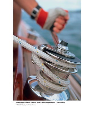
  • 1. Large changes in tension can occur when a line is wrapped around a fixed cylinder. © STOCK4B-RoyaltyFree/Image Source
  • 2. 335 6/1 Introduction Section A Frictional Phenomena 6/2 Types of Friction 6/3 Dry Friction Section B Applications of Friction in Machines 6/4 Wedges 6/5 Screws 6/6 Journal Bearings 6/7 Thrust Bearings; Disk Friction 6/8 Flexible Belts 6/9 Rolling Resistance 6/10 Chapter Review CHAPTER OUTLINE 6Friction 6/1 Introduction In the preceding chapters we have usually assumed that the forces of action and reaction between contacting surfaces act normal to the surfaces. This assumption characterizes the interaction between smooth surfaces and was illustrated in Example 2 of Fig. 3/1. Although this ideal assumption often involves only a relatively small error, there are many problems in which we must consider the ability of contacting sur- faces to support tangential as well as normal forces. Tangential forces generated between contacting surfaces are called friction forces and occur to some degree in the interaction between all real surfaces. When- ever a tendency exists for one contacting surface to slide along another surface, the friction forces developed are always in a direction to oppose this tendency. In some types of machines and processes we want to minimize the retarding effect of friction forces. Examples are bearings of all types, power screws, gears, the flow of fluids in pipes, and the propulsion of aircraft and missiles through the atmosphere. In other situations we wish to maximize the effects of friction, as in brakes, clutches, belt drives, and wedges. Wheeled vehicles depend on friction for both start- ing and stopping, and ordinary walking depends on friction between the shoe and the ground.
  • 3. Friction forces are present throughout nature and exist in all ma- chines no matter how accurately constructed or carefully lubricated. A machine or process in which friction is small enough to be neglected is said to be ideal. When friction must be taken into account, the machine or process is termed real. In all cases where there is sliding motion be- tween parts, the friction forces result in a loss of energy which is dissi- pated in the form of heat. Wear is another effect of friction. SECTION A FRICTIONAL PHENOMENA 6/2 Types of Friction In this article we briefly discuss the types of frictional resistance en- countered in mechanics. The next article contains a more detailed ac- count of the most common type of friction, dry friction. (a) Dry Friction. Dry friction occurs when the unlubricated surfaces of two solids are in contact under a condition of sliding or a tendency to slide. A friction force tangent to the surfaces of contact occurs both dur- ing the interval leading up to impending slippage and while slippage takes place. The direction of this friction force always opposes the mo- tion or impending motion. This type of friction is also called Coulomb friction. The principles of dry or Coulomb friction were developed largely from the experiments of Coulomb in 1781 and from the work of Morin from 1831 to 1834. Although we do not yet have a comprehensive theory of dry friction, in Art. 6/3 we describe an analytical model suffi- cient to handle the vast majority of problems involving dry friction. This model forms the basis for most of this chapter. (b) Fluid Friction. Fluid friction occurs when adjacent layers in a fluid (liquid or gas) are moving at different velocities. This motion causes frictional forces between fluid elements, and these forces depend on the relative velocity between layers. When there is no relative veloc- ity, there is no fluid friction. Fluid friction depends not only on the ve- locity gradients within the fluid but also on the viscosity of the fluid, which is a measure of its resistance to shearing action between fluid lay- ers. Fluid friction is treated in the study of fluid mechanics and will not be discussed further in this book. (c) Internal Friction. Internal friction occurs in all solid materials which are subjected to cyclical loading. For highly elastic materials the recovery from deformation occurs with very little loss of energy due to internal friction. For materials which have low limits of elasticity and which undergo appreciable plastic deformation during loading, a consid- erable amount of internal friction may accompany this deformation. The mechanism of internal friction is associated with the action of shear deformation, which is discussed in references on materials science. Be- cause this book deals primarily with the external effects of forces, we will not discuss internal friction further. 336 Chapter 6 Friction
  • 4. 6/3 Dry Friction The remainder of this chapter describes the effects of dry friction acting on the exterior surfaces of rigid bodies. We will now explain the mechanism of dry friction with the aid of a very simple experiment. Mechanism of Dry Friction Consider a solid block of mass m resting on a horizontal surface, as shown in Fig. 6/1a. We assume that the contacting surfaces have some roughness. The experiment involves the application of a horizontal force P which continuously increases from zero to a value sufficient to move the block and give it an appreciable velocity. The free-body diagram of the block for any value of P is shown in Fig. 6/1b, where the tangential friction force exerted by the plane on the block is labeled F. This friction force acting on the body will always be in a direction to oppose motion or the tendency toward motion of the body. There is also a normal force N which in this case equals mg, and the total force R exerted by the sup- porting surface on the block is the resultant of N and F. A magnified view of the irregularities of the mating surfaces, Fig. 6/1c, helps us to visualize the mechanical action of friction. Support is necessarily intermittent and exists at the mating humps. The direction of each of the reactions on the block, R1, R2, R3, etc. depends not only on the geometric profile of the irregularities but also on the extent of local deformation at each contact point. The total normal force N is the sum Article 6/3 Dry Friction 337 Pm P F α RN mg (a) (c) t n F F = P Fmax = s Nμ Fk = k Nμ R1 R3R2 (b) P Static friction (no motion) Kinetic friction (motion) Impending motion (d) Figure 6/1
  • 5. of the n-components of the R’s, and the total frictional force F is the sum of the t-components of the R’s. When the surfaces are in relative motion, the contacts are more nearly along the tops of the humps, and the t-components of the R’s are smaller than when the surfaces are at rest relative to one another. This observation helps to explain the well- known fact that the force P necessary to maintain motion is generally less than that required to start the block when the irregularities are more nearly in mesh. If we perform the experiment and record the friction force F as a function of P, we obtain the relation shown in Fig. 6/1d. When P is zero, equilibrium requires that there be no friction force. As P is in- creased, the friction force must be equal and opposite to P as long as the block does not slip. During this period the block is in equilibrium, and all forces acting on the block must satisfy the equilibrium equa- tions. Finally, we reach a value of P which causes the block to slip and to move in the direction of the applied force. At this same time the friction force decreases slightly and abruptly. It then remains essen- tially constant for a time but then decreases still more as the velocity increases. Static Friction The region in Fig. 6/1d up to the point of slippage or impending mo- tion is called the range of static friction, and in this range the value of the friction force is determined by the equations of equilibrium. This friction force may have any value from zero up to and including the maximum value. For a given pair of mating surfaces the experiment shows that this maximum value of static friction Fmax is proportional to the normal force N. Thus, we may write (6/1) where ␮s is the proportionality constant, called the coefficient of static friction. Be aware that Eq. 6/1 describes only the limiting or maximum value of the static friction force and not any lesser value. Thus, the equation applies only to cases where motion is impending with the friction force at its peak value. For a condition of static equilibrium when motion is not impending, the static friction force is Kinetic Friction After slippage occurs, a condition of kinetic friction accompanies the ensuing motion. Kinetic friction force is usually somewhat less than the maximum static friction force. The kinetic friction force Fk is also pro- portional to the normal force. Thus, (6/2)Fk ϭ ␮kN F Ͻ ␮s N Fmax ϭ ␮s N 338 Chapter 6 Friction
  • 6. where ␮k is the coefficient of kinetic friction. It follows that ␮k is gener- ally less than ␮s. As the velocity of the block increases, the kinetic fric- tion decreases somewhat, and at high velocities, this decrease may be significant. Coefficients of friction depend greatly on the exact condition of the surfaces, as well as on the relative velocity, and are subject to con- siderable uncertainty. Because of the variability of the conditions governing the action of friction, in engineering practice it is frequently difficult to distinguish between a static and a kinetic coefficient, especially in the region of transition between impending motion and motion. Well-greased screw threads under mild loads, for example, often exhibit comparable fric- tional resistance whether they are on the verge of turning or whether they are in motion. In the engineering literature we frequently find expressions for max- imum static friction and for kinetic friction written simply as F ϭ ␮N. It is understood from the problem at hand whether maximum static fric- tion or kinetic friction is described. Although we will frequently distin- guish between the static and kinetic coefficients, in other cases no distinction will be made, and the friction coefficient will be written simply as ␮. In those cases you must decide which of the friction condi- tions, maximum static friction for impending motion or kinetic fric- tion, is involved. We emphasize again that many problems involve a static friction force which is less than the maximum value at impend- ing motion, and therefore under these conditions the friction relation Eq. 6/1 cannot be used. Figure 6/1c shows that rough surfaces are more likely to have larger angles between the reactions and the n-direction than are smoother surfaces. Thus, for a pair of mating surfaces, a friction coef- ficient reflects the roughness, which is a geometric property of the surfaces. With this geometric model of friction, we describe mating surfaces as “smooth” when the friction forces they can support are negligibly small. It is meaningless to speak of a coefficient of friction for a single surface. Friction Angles The direction of the resultant R in Fig. 6/1b measured from the direction of N is specified by tan ␣ ϭ F/N. When the friction force reaches its limiting static value Fmax, the angle ␣ reaches a maximum value ␾s. Thus, When slippage is occurring, the angle ␣ has a value ␾k corresponding to the kinetic friction force. In like manner, In practice we often see the expression tan ␾ ϭ ␮, in which the coefficient of friction may refer to either the static or the kinetic case, tan ␾k ϭ ␮k tan ␾s ϭ ␮s Article 6/3 Dry Friction 339 This tree surgeon depends on the friction between the rope and the mechanical devices through which the rope can slip. ©BlackoutConcepts/Stockphotopro,Inc
  • 7. depending on the particular problem. The angle ␾s is called the angle of static friction, and the angle ␾k is called the angle of kinetic friction. The friction angle for each case clearly defines the limiting direction of the total reaction R between two contacting surfaces. If motion is impend- ing, R must be one element of a right-circular cone of vertex angle 2␾s, as shown in Fig. 6/2. If motion is not impending, R is within the cone. This cone of vertex angle 2␾s is called the cone of static friction and rep- resents the locus of possible directions for the reaction R at impending motion. If motion occurs, the angle of kinetic friction applies, and the reaction must lie on the surface of a slightly different cone of vertex angle 2␾k. This cone is the cone of kinetic friction. Factors Affecting Friction Further experiment shows that the friction force is essentially in- dependent of the apparent or projected area of contact. The true con- tact area is much smaller than the projected value, since only the peaks of the contacting surface irregularities support the load. Even rela- tively small normal loads result in high stresses at these contact points. As the normal force increases, the true contact area also increases as the material undergoes yielding, crushing, or tearing at the points of contact. A comprehensive theory of dry friction must go beyond the mechan- ical explanation presented here. For example, there is evidence that molecular attraction may be an important cause of friction under condi- tions where the mating surfaces are in very close contact. Other factors which influence dry friction are the generation of high local tempera- tures and adhesion at contact points, relative hardness of mating sur- faces, and the presence of thin surface films of oxide, oil, dirt, or other substances. Some typical values of coefficients of friction are given in Table D/1, Appendix D. These values are only approximate and are subject to con- siderable variation, depending on the exact conditions prevailing. They may be used, however, as typical examples of the magnitudes of fric- tional effects. To make a reliable calculation involving friction, the appropriate friction coefficient should be determined by experiments which duplicate the surface conditions of the application as closely as possible. 340 Chapter 6 Friction Cone of static friction 2 kφ 2 sφ Cone of kinetic friction R Figure 6/2
  • 8. Article 6/3 Dry Friction 341 Types of Friction Problems We can now recognize the following three types of problems encoun- tered in applications involving dry friction. The first step in solving a friction problem is to identify its type. 1. In the first type of problem, the condition of impending motion is known to exist. Here a body which is in equilibrium is on the verge of slipping, and the friction force equals the limiting static friction Fmax ϭ ␮sN. The equations of equilibrium will, of course, also hold. 2. In the second type of problem, neither the condition of impending motion nor the condition of motion is known to exist. To determine the actual friction conditions, we first assume static equilibrium and then solve for the friction force F necessary for equilibrium. Three outcomes are possible: (a) F Ͻ (Fmax ϭ ␮sN): Here the friction force necessary for equilibrium can be supported, and therefore the body is in static equilibrium as assumed. We emphasize that the actual friction force F is less than the limiting value Fmax given by Eq. 6/1 and that F is determined solely by the equations of equilibrium. (b) F ϭ (Fmax ϭ ␮sN): Since the friction force F is at its maximum value Fmax, motion impends, as discussed in problem type (1). The assumption of static equilibrium is valid. (c) F Ͼ (Fmax ϭ ␮sN): Clearly this condition is impossible, because the surfaces cannot support more force than the maximum ␮sN. The assumption of equilibrium is therefore invalid, and motion occurs. The friction force F is equal to ␮kN from Eq. 6/2. 3. In the third type of problem, relative motion is known to exist between the contacting surfaces, and thus the kinetic coefficient of friction clearly applies. For this problem type, Eq. 6/2 always gives the kinetic friction force directly. KEY CONCEPTS The foregoing discussion applies to all dry contacting surfaces and, to a limited extent, to moving surfaces which are partially lubricated.
  • 9. SAMPLE PROBLEM 6/1 Determine the maximum angle ␪ which the adjustable incline may have with the horizontal before the block of mass m begins to slip. The coefficient of static friction between the block and the inclined surface is ␮s. Solution. The free-body diagram of the block shows its weight W ϭ mg, the normal force N, and the friction force F exerted by the incline on the block. The friction force acts in the direction to oppose the slipping which would occur if no friction were present. Equilibrium in the x- and y-directions requires Dividing the first equation by the second gives F/N ϭ tan ␪. Since the maximum angle occurs when F ϭ Fmax ϭ ␮sN, for impending motion we have Ans. SAMPLE PROBLEM 6/2 Determine the range of values which the mass m0 may have so that the 100-kg block shown in the figure will neither start moving up the plane nor slip down the plane. The coefficient of static friction for the contact surfaces is 0.30. Solution. The maximum value of m0 will be given by the requirement for mo- tion impending up the plane. The friction force on the block therefore acts down the plane, as shown in the free-body diagram of the block for Case I in the figure. With the weight mg ϭ 100(9.81) ϭ 981 N, the equations of equilibrium give Ans. The minimum value of m0 is determined when motion is impending down the plane. The friction force on the block will act up the plane to oppose the ten- dency to move, as shown in the free-body diagram for Case II. Equilibrium in the x-direction requires Ans. Thus, m0 may have any value from 6.01 to 62.4 kg, and the block will remain at rest. In both cases equilibrium requires that the resultant of Fmax and N be con- current with the 981-N weight and the tension T. m0(9.81) ϩ 277 Ϫ 981 sin 20Њ ϭ 0 m0 ϭ 6.01 kg[ΣFx ϭ 0] m0(9.81) Ϫ 277 Ϫ 981 sin 20Њ ϭ 0 m0 ϭ 62.4 kg[ΣFx ϭ 0] Fmax ϭ 0.30(922) ϭ 277 N[Fmax ϭ ␮s N] N Ϫ 981 cos 20Њ ϭ 0 N ϭ 922 N[ΣFy ϭ 0] ␮s ϭ tan ␪max or ␪max ϭ tanϪ1 ␮s Ϫmg cos ␪ ϩ N ϭ 0 N ϭ mg cos ␪[ΣFy ϭ 0] mg sin ␪ Ϫ F ϭ 0 F ϭ mg sin ␪[ΣFx ϭ 0] 342 Chapter 6 Friction m θ sμ x y F N W = mg θ 20° m0 100 kg 20° 981 N N Case I x y Fmax Fmax T = m0 g 20° 981 N N Case II x y T = m0 g ᕡ ᕢ ᕡ Helpful Hints ᕡ We choose reference axes along and normal to the direction of F to avoid resolving both F and N into components. ᕢ This problem describes a very simple way to determine a static coefficient of friction. The maximum value of ␪ is known as the angle of repose. Helpful Hint ᕡ We see from the results of Sample Problem 6/1 that the block would slide down the incline without the re- straint of attachment to m0 since tan 20Њ Ͼ 0.30. Thus, a value of m0 will be required to maintain equilibrium.
  • 10. SAMPLE PROBLEM 6/3 Determine the magnitude and direction of the friction force acting on the 100-kg block shown if, first, P ϭ 500 N and, second, P ϭ 100 N. The coefficient of static friction is 0.20, and the coefficient of kinetic friction is 0.17. The forces are applied with the block initially at rest. Solution. There is no way of telling from the statement of the problem whether the block will remain in equilibrium or whether it will begin to slip following the application of P. It is therefore necessary that we make an assumption, so we will take the friction force to be up the plane, as shown by the solid arrow. From the free-body diagram a balance of forces in both x- and y-directions gives Case I. P ϭ 500 N Substitution into the first of the two equations gives The negative sign tells us that if the block is in equilibrium, the friction force acting on it is in the direction opposite to that assumed and therefore is down the plane, as represented by the dashed arrow. We cannot reach a conclusion on the magnitude of F, however, until we verify that the surfaces are capable of supporting 134.3 N of friction force. This may be done by substituting P ϭ 500 N into the second equation, which gives The maximum static friction force which the surfaces can support is then Since this force is greater than that required for equilibrium, we conclude that the assumption of equilibrium was correct. The answer is, then, Ans. Case II. P ϭ 100 N Substitution into the two equilibrium equations gives But the maximum possible static friction force is It follows that 242 N of friction cannot be supported. Therefore, equilibrium cannot exist, and we obtain the correct value of the friction force by using the kinetic coeffi- cient of friction accompanying the motion down the plane. Hence, the answer is Ans.F ϭ 0.17(956) ϭ 162.5 N up the plane[Fk ϭ ␮k N] Fmax ϭ 0.20(956) ϭ 191.2 N[Fmax ϭ ␮s N] F ϭ 242 N N ϭ 956 N F ϭ 134.3 N down the plane Fmax ϭ 0.20(1093) ϭ 219 N[Fmax ϭ ␮s N] N ϭ 1093 N F ϭ Ϫ134.3 N N Ϫ P sin 20Њ Ϫ 981 cos 20Њ ϭ 0[ΣFy ϭ 0] P cos 20Њ ϩ F Ϫ 981 sin 20Њ ϭ 0[ΣFx ϭ 0] Article 6/3 Dry Friction 343 20° P 100 kg 20° 100(9.81) = 981 N P N F x y F ᕡ Helpful Hint ᕡ We should note that even though ΣFx is no longer equal to zero, equilibrium does exist in the y-direction, so that ΣFy ϭ 0. Therefore, the normal force N is 956 N whether or not the block is in equilibrium.
  • 11. SAMPLE PROBLEM 6/4 The homogeneous rectangular block of mass m, width b, and height H is placed on the horizontal surface and subjected to a horizontal force P which moves the block along the surface with a constant velocity. The coefficient of ki- netic friction between the block and the surface is ␮k. Determine (a) the greatest value which h may have so that the block will slide without tipping over and (b) the location of a point C on the bottom face of the block through which the resultant of the friction and normal forces acts if h ϭ H/2. Solution. (a) With the block on the verge of tipping, we see that the entire re- action between the plane and the block will necessarily be at A. The free-body diagram of the block shows this condition. Since slipping occurs, the friction force is the limiting value ␮kN, and the angle ␪ becomes ␪ ϭ tanϪ1 ␮k. The resul- tant of Fk and N passes through a point B through which P must also pass, since three coplanar forces in equilibrium are concurrent. Hence, from the geometry of the block Ans. If h were greater than this value, moment equilibrium about A would not be satisfied, and the block would tip over. Alternatively, we may find h by combining the equilibrium requirements for the x- and y-directions with the moment-equilibrium equation about A. Thus, Ans. (b) With h ϭ H/2 we see from the free-body diagram for case (b) that the re- sultant of Fk and N passes through a point C which is a distance x to the left of the vertical centerline through G. The angle ␪ is still ␪ ϭ ␾ ϭ tanϪ1 ␮k as long as the block is slipping. Thus, from the geometry of the figure we have Ans. If we were to replace ␮k by the static coefficient ␮s, then our solutions would describe the conditions under which the block is (a) on the verge of tipping and (b) on the verge of slipping, both from a rest position. x H/2 ϭ tan ␪ ϭ ␮k so x ϭ ␮k H/2 Ph Ϫ mg b 2 ϭ 0 h ϭ mgb 2P ϭ mgb 2␮kmg ϭ b 2␮k [ΣMA ϭ 0] Fk Ϫ P ϭ 0 P ϭ Fk ϭ ␮k N ϭ ␮kmg[ΣFx ϭ 0] N Ϫ mg ϭ 0 N ϭ mg[ΣFy ϭ 0] tan ␪ ϭ ␮k ϭ b/2 h h ϭ b 2␮k 344 Chapter 6 Friction P m b H h P G mg θ θ x y B A N Fk h b — 2 P G mg θ θ C N xFk H — 2 ᕡ ᕢ Helpful Hints ᕡ Recall that the equilibrium equa- tions apply to a body moving with a constant velocity (zero acceleration) just as well as to a body at rest. ᕢ Alternatively, we could equate the moments about G to zero, which would give us F(H/2) Ϫ Nx ϭ 0. Thus, with Fk ϭ ␮kN we get x ϭ ␮xH/2.
  • 12. SAMPLE PROBLEM 6/5 The three flat blocks are positioned on the 30Њ incline as shown, and a force P parallel to the incline is applied to the middle block. The upper block is pre- vented from moving by a wire which attaches it to the fixed support. The coeffi- cient of static friction for each of the three pairs of mating surfaces is shown. Determine the maximum value which P may have before any slipping takes place. Solution. The free-body diagram of each block is drawn. The friction forces are assigned in the directions to oppose the relative motion which would occur if no friction were present. There are two possible conditions for impending mo- tion. Either the 50-kg block slips and the 40-kg block remains in place, or the 50- and 40-kg blocks move together with slipping occurring between the 40-kg block and the incline. The normal forces, which are in the y-direction, may be determined without reference to the friction forces, which are all in the x-direction. Thus, We will assume arbitrarily that only the 50-kg block slips, so that the 40-kg block remains in place. Thus, for impending slippage at both surfaces of the 50-kg block, we have The assumed equilibrium of forces at impending motion for the 50-kg block gives We now check on the validity of our initial assumption. For the 40-kg block with F2 ϭ 272 N the friction force F3 would be given by But the maximum possible value of F3 is F3 ϭ ␮sN3 ϭ 0.45(1019) ϭ 459 N. Thus, 468 N cannot be supported and our initial assumption was wrong. We conclude, therefore, that slipping occurs first between the 40-kg block and the incline. With the corrected value F3 ϭ 459 N, equilibrium of the 40-kg block for its im- pending motion requires Equilibrium of the 50-kg block gives, finally, Ans. Thus, with P ϭ 93.8 N, motion impends for the 50-kg and 40-kg blocks as a unit. P ϭ 93.8 N P ϩ 50(9.81) sin 30Њ Ϫ 263 Ϫ 76.5 ϭ 0[ΣFx ϭ 0] F2 ϩ 40(9.81) sin 30Њ Ϫ 459 ϭ 0 F2 ϭ 263 N[ΣFx ϭ 0] 272 ϩ 40(9.81) sin 30Њ Ϫ F3 ϭ 0 F3 ϭ 468 N[ΣFx ϭ 0] P Ϫ 76.5 Ϫ 272 ϩ 50(9.81) sin 30Њ ϭ 0 P ϭ 103.1 N[ΣFx ϭ 0] F1 ϭ 0.30(255) ϭ 76.5 N F2 ϭ 0.40(680) ϭ 272 N[Fmax ϭ ␮s N] (40-kg) N3 Ϫ 40(9.81) cos 30Њ Ϫ 680 ϭ 0 N3 ϭ 1019 N (50-kg) N2 Ϫ 50(9.81) cos 30Њ Ϫ 255 ϭ 0 N2 ϭ 680 N (30-kg) N1 Ϫ 30(9.81) cos 30Њ ϭ 0 N1 ϭ 255 N[ΣFy ϭ 0] Article 6/3 Dry Friction 345 P 30 kg s = 0.30 μ s = 0.40 μ 50 kg 40 kg 30° s = 0.45 μ 30° y P F1 F2 N2 N1 50(9.81) N x y F1 T N1 30(9.81) N x x y F2 F3 N3 N2 40(9.81) N Helpful Hints ᕡ In the absence of friction the middle block, under the influence of P, would have a greater movement than the 40-kg block, and the fric- tion force F2 will be in the direction to oppose this motion as shown. ᕢ We see now that F2 is less than ␮s N2 ϭ 272 N. ᕢ ᕡ
  • 13. 6/4 The coefficients of static and kinetic friction be- tween the 100-kg block and the inclined plane are 0.30 and 0.20, respectively. Determine (a) the fric- tion force F acting on the block when P is applied with a magnitude of 200 N to the block at rest, (b) the force P required to initiate motion up the in- cline from rest, and (c) the friction force F acting on the block if P = 600 N. Problem 6/4 6/5 The magnitude of force P is slowly increased. Does the homogeneous box of mass m slip or tip first? State the value of P which would cause each occur- rence. Neglect any effect of the size of the small feet. Problem 6/5 P d A B C 2d 30° s = 0.50μ m 20° 15° 100 kg P s = 0.30μ k = 0.20μ 346 Chapter 6 Friction PROBLEMS Introductory Problems 6/1 The 85-lb force P is applied to the 200-lb crate, which is stationary before the force is applied. De- termine the magnitude and direction of the friction force F exerted by the horizontal surface on the crate. Problem 6/1 6/2 The 700-N force is applied to the 100-kg block, which is stationary before the force is applied. De- termine the magnitude and direction of the friction force F exerted by the horizontal surface on the block. Problem 6/2 6/3 The designer of a ski resort wishes to have a portion of a beginner’s slope on which the skier’s speed will remain fairly constant. Tests indicate the average coefficients of friction between skis and snow to be and . What should be the slope angle of the constant-speed section? Problem 6/3 θ ␪ ␮k ϭ 0.08␮s ϭ 0.10 100 kg 30° P = 700 N s = 0.80μ k = 0.60μ P = 85 lb 200 lb s = 0.50μ k = 0.40μ
  • 14. 6/6 Determine the magnitude and direction of the fric- tion force which the vertical wall exerts on the 100-lb block if (a) and (b) . Problem 6/6 6/7 Determine the minimum coefficient of static friction which will allow the drum with fixed inner hub to be rolled up the incline at a steady speed without slipping. What are the corresponding values of the force P and the friction force F? Problem 6/7 6/8 The tongs are designed to handle hot steel tubes which are being heat-treated in an oil bath. For a jaw opening, what is the minimum coefficient of static friction between the jaws and the tube which will enable the tongs to grip the tube with- out slipping? 20Њ 30° P 15° m r r/2 s μ 15Њ ␮s 100 lb P = 120 lb s = 0.50 θ μ k = 0.40μ ␪ ϭ 30Њ␪ ϭ 15Њ Article 6/3 Problems 347 Problem 6/8 6/9 The light bar is used to support the 50-kg block in its vertical guides. If the coefficient of static fric- tion is 0.30 at the upper end of the bar and 0.40 at the lower end of the bar, find the friction force act- ing at each end for x = 75 mm. Also find the maxi- mum value of x for which the bar will not slip. Problem 6/9 6/10 The semicircular 5-kg plate rotates about a fixed bearing at O that can exert a maximum frictional moment of 1.2 N m on the plate. The horizontal force P is applied to a cord wrapped around the plate periphery and pinned at A. (a) With P = 0, deter- mine the maximum angle for which equilibrium is possible. (b) From the position determined in (a) calculate the force P required to rotate the body counterclockwise. Problem 6/10 P θO A 0.2 m ␪ ⅐ 50 kg x 300mm A B F F 20°
  • 15. Problem 6/13 6/14 The illustration shows the design of a cam-type locking device, which, in the presence of sufficient friction, limits the movement of body B to be to the left only; rightward movement is prevented. The surface of the cam near point D is circular with cen- ter at C. Given the distance L, specify the cam offset d so that the device will work if the coefficient of static friction is 0.20 or greater. Problem 6/14 6/15 The uniform slender bar has an ideal roller at its upper end A. If the coefficient of static friction at B is , determine the minimum angle for which equilibrium is possible. Repeat for . Problem 6/15 B A θ ms = 0.25, 0.50 ␮s ϭ 0.50 ␪␮s ϭ 0.25 OC d A L Allowable motion No motion DB ␮s 25 lb 24′′ 100 lb 3′′ 8′′ θ 348 Chapter 6 Friction 6/11 The homogeneous body with two small feet and two ideal wheels is at rest on the rough incline. (a) As- sume no slippage and determine the maximum value of the angle for which the body does not overturn about feet A. (b) If , determine the maxi- mum value of the angle for which the body does not slip. (c) If and side C of the body now faces up the incline, determine the maximum value of the angle for which the body does not slip. Problem 6/11 6/12 The strut AB of negligible mass is hinged to the hori- zontal surface at A and to the uniform 25-kg wheel at B. Determine the minimum couple M applied to the wheel which will cause it to slip if the coefficient of sta- tic friction between the wheel and the surface is 0.40. Problem 6/12 Representative Problems 6/13 The 100-lb wheel rolls on its hub up the circular in- cline under the action of the 25-lb weight attached to a cord around the rim. Determine the angle at which the wheel comes to rest, assuming that fric- tion is sufficient to prevent slippage. What is the minimum coefficient of friction which will permit this position to be reached with no slipping? ␪ A B 150 m m 250 m m M h/4 h/2 h/4 h/2 C G A B q ms ␪ ␮s ϭ 0.40 ␪ ␮s ϭ 0.40 ␪
  • 16. 6/16 The upper end of the bar of Prob. 6/15 is now leaned against a nonvertical wall. Determine the minimum value of the angle for which equilibrium is possible for and for . Problem 6/16 6/17 A person (mass m1) who is kneeling on a plywood panel (mass m2) wishes to push himself and the panel away from the right-hand wall. Determine a condition on which would allow him to do this, as opposed to his slipping relative to a stationary panel. The two applicable coefficients of static fric- tion are and . Evaluate for m1 = 80 kg, m2 = 10 kg, and . Problem 6/17 6/18 The homogeneous rectangular block of mass m rests on the inclined plane which is hinged about a hori- zontal axis through O. If the coefficient of static fric- tion between the block and the plane is , specify the conditions which determine whether the block tips before it slips or slips before it tips as the angle is gradually increased.␪ ␮ m1 m22μ 1μ ␮1 ϭ 0.60 ␮2␮2␮1 ␮2 B 105° θ ms = 0.25, 0.50 A ␮s ϭ 0.50␮s ϭ 0.25 ␪ Article 6/3 Problems 349 Problem 6/18 6/19 A loaded wheelbarrow is placed on a rough incline. The combined weight of the wheelbarrow and its load acts at the center of gravity G. (a) Determine the maximum angle for which the wheelbarrow will not slip. (b) Repeat if the wheelbarrow faces uphill. Neglect all friction associated with the front wheel B. Problem 6/19 6/20 The force P is applied to (a) the 60-lb block and (b) the 100-lb block. For each case, determine the magnitude of P required to initiate motion. Problem 6/20 6/21 Calculate the magnitude of the clockwise couple M required to turn the 50-kg cylinder in the supporting block shown. The coefficient of kinetic friction is 0.30. Problem 6/21 900 mm 30° M 60° 60 lb 100 lb P (a) P (b) s = 0.40μ s = 0.12μ B A G 21″ 8″ 20″ ms = 0.80 q ␪ a O b θ
  • 17. 6/24 A clockwise couple M is applied to the circular cylin- der as shown. Determine the value of M required to initiate motion for the conditions , , , , and r = 0.2 m. Friction between the cylinder C and the block B is negligible. Problem 6/24 6/25 Determine the range of weights W for which the 100-lb block is in equilibrium. All wheels and pul- leys have negligible friction. Problem 6/25 6/26 A 100-kg roofer crouches on an 18-kg sheet of plywood as he is about to effect a shingle repair. Determine the friction force which the roof surface exerts on the plywood if the coefficients of static friction are (a) and and (b) and . In all cases, the co- efficient of kinetic friction is 75% of the static value. Problem 6/26 12 5 ( s)2, ( k)2μ μ ( s)1, ( k)1μ μ m2 m1 (␮s)2 ϭ 0.40(␮s)1 ϭ 0.50 (␮s)2 ϭ 0.50(␮s)1 ϭ 0.60 s = 0.30μ k = 0.25μ 100 lb W 20° 10° mB mC s C μ( ) s B μ( )r M (␮s)C ϭ 0.40(␮s)B ϭ 0.50mC ϭ 6 kg mB ϭ 3 kg 350 Chapter 6 Friction 6/22 The inverted track T with freely floating cylinder C comprise a system which is designed to hold paper or other thin materials P in place. The coefficient of static friction is for all interfaces. What minimum value of ensures that the device will work no mat- ter how heavy the supported material P is? Problem 6/22 6/23 The sliding glass door rolls on the two small lower wheels A and B. Under normal conditions the upper wheels do not touch their horizontal guide. (a) Com- pute the force P required to slide the door at a steady speed if wheel A becomes “frozen” and does not turn in its bearing. (b) Rework the problem if wheel B becomes frozen instead of wheel A. The co- efficient of kinetic friction between a frozen wheel and the supporting surface is 0.30, and the center of mass of the 140-lb door is at its geometric center. Neglect the small diameter of the wheels. Problem 6/23 40′′ 28′′ 6′′ 6′′ 40′′ P BA T P C 30° ␮ ␮
  • 18. 6/27 Determine the distance s to which the 90-kg painter can climb without causing the 4-m ladder to slip at its lower end A. The top of the 15-kg ladder has a small roller, and at the ground the coefficient of sta- tic friction is 0.25. The mass center of the painter is directly above her feet. Problem 6/27 6/28 The 1600-kg car is just beginning to negotiate the ramp. If the car has rear-wheel drive, determine the minimum coefficient of static friction required at B. Problem 6/28 6/29 Repeat Prob. 6/28, but now the car has front-wheel drive. 6/30 Repeat Prob. 6/28, but now the car has all-wheel drive. Assume that slipping occurs at A and B simultaneously. 6/31 The rectangular steel yoke is used to prevent slip- page between the two boards under tensile loads P. If the coefficients of static friction between the yoke and the board surfaces and between the boards are all 0.30, determine the maximum value of h for which there is no slipping. For P = 800 N, deter- mine the corresponding normal force N between the two boards if motion impends at all surfaces. B A 1070 mm 16° 1475 mm G 315 mm 185 mm 16Њ 1.5 m s 4 m B A Article 6/3 Problems 351 Problem 6/31 6/32 The figure shows the design in section of a loaded bracket which is supported on the fixed shaft by the roller at B and by friction at the corner A. The coef- ficient of static friction is 0.40. Neglect the weight of the bracket and show that the bracket as designed will remain in place. Find the friction force F. Problem 6/32 6/33 The homogeneous square body is positioned as shown. If the coefficient of static friction at B is 0.40, determine the critical value of the angle below which slipping will occur. Neglect friction at A. Problem 6/33 B s s A 60° θ ␪ 20" 4" B A 6" 400 lb h P P 210 mm 150 mm 200 mm
  • 19. 6/37 The 10-kg solid cylinder is resting in the inclined V-block. If the coefficient of static friction between the cylinder and the block is 0.50, determine (a) the friction force F acting on the cylinder at each side before force P is applied and (b) the value of P required to start sliding the cylinder up the incline. Problem 6/37 6/38 The three identical rollers are stacked on a horizon- tal surface as shown. If the coefficient of static friction is the same for all pairs of contacting sur- faces, find the minimum value of for which the rollers will not slip. Problem 6/38 ␮s ␮s 45° 45° End View 30° Horiz. P 352 Chapter 6 Friction 6/34 Determine the range of weights W of the uniform slender bar for which the system will be in equilib- rium. Neglect friction at all bearings. Problem 6/34 6/35 The uniform rod with center of mass at G is sup- ported by the pegs A and B, which are fixed in the wheel. If the coefficient of friction between the rod and pegs is , determine the angle through which the wheel may be slowly turned about its horizontal axis through O, starting from the position shown, before the rod begins to slip. Neglect the diameter of the rod compared with the other dimensions. Problem 6/35 6/36 The solid semicylinder of mass m and radius r is rolled through an angle by the horizontal force P. If the coefficient of static friction is , determine the angle at which the cylinder begins to slip on the horizontal surface as P is gradually increased. What value of would permit to reach ? Problem 6/36 P θ r 90Њ␪␮s ␪ ␮s ␪ B G A a a b θ ␪␮ 30° 30° ms = 0.40 100 lb 2L/3 L/3 W A O 30°
  • 20. 6/39 The movable left-hand jaw of the bar clamp can be slid along the frame to increase the capacity of the clamp. To prevent slipping of the jaw on the frame when the clamp is under load, the dimension x must exceed a certain minimum value. For given values of a and b and a static friction coefficient , specify this design minimum value of x to prevent slipping of the jaw. Problem 6/39 6/40 The uniform slender bar of length l is placed in the opening of width d at the angle shown. For what range of l/d will the bar remain in static equilib- rium? The coefficient of static friction at A and B is . Problem 6/40 6/41 Determine the maximum value of the angle for which the uniform slender rod will remain in equi- librium. The coefficient of static friction at A is , and friction associated with the small roller at B may be neglected. ␮A ϭ 0.80 ␪ l B A d 30° ␮s ϭ 0.40 30Њ x b a ␮s Article 6/3 Problems 353 Problem 6/41 6/42 A uniform block of mass m is at rest on an incline . Determine the maximum force P which can be ap- plied to the block in the direction shown before slipping begins. The coefficient of static friction between the block and the incline is . Also deter- mine the angle between the horizontal direction of P and the direction of initial movement of the block. Problem 6/42 6/43 The single-lever block brake prevents rotation of the flywheel under a counterclockwise torque M. Find the force P required to prevent rotation if the coefficient of static friction is . Explain what would happen if the geometry permitted b to equal . Problem 6/43 l b e r M P ␮se ␮s θ P ␤ ␮s ␪ A R B 2R
  • 21. Problem 6/46 6/47 Two workers are carrying a 2-in.-thick panel by means of panel carriers, one of which is shown in the detail figures. The vertical panel is steadied by equal horizontal forces applied by the left hands of the workers. Determine the minimum coefficient of static friction between the panel and the carriers for which there will be no slippage. The carrier grips at A, B, and C do not rotate on the carrier frame. Note that each worker must apply both a vertical and a horizontal force to the carrier handle. Assume that each worker supports half the weight of the panel. 12° 900 kg O 354 Chapter 6 Friction 6/44 Determine the minimum value of for which equilib- rium is possible if (a) and and (b) and . Problem 6/44 6/45 The industrial truck is used to move the solid 1200- kg roll of paper up the incline. If the coefficients of static and kinetic friction between the roll and the vertical barrier of the truck and between the roll and the incline are both 0.40, compute the required tractive force P between the tires of the truck and the horizontal surface. Problem 6/45 6/46 Heavy-duty plate clamps with wedging cams are designed to be used in pairs to lift and transport large steel plates. As each cam begins to take effect, the plate slips down slightly against the vertical sur- face of the clamp and, therefore, generates limiting static friction at that interface. If the coefficient of static friction for all contacting surfaces is 0.30, calculate the force R supported by the pin at O for each of the two clamps symmetrically placed on the 900-kg plate. 30° 30Њ A q B 15° 50° (ms)B (ms)A (␮s)B ϭ 0.10(␮s)A ϭ 0.40 (␮s)B ϭ 0.20(␮s)A ϭ 0.60 ␪ 2″ 30″ A B C 3.5″ 30° Problem 6/47
  • 22. 6/48 The uniform slender rod is slowly lowered from the upright position by means of the cord at- tached to its upper end and passing under the small fixed pulley. If the rod is observed to slip at its lower end when , determine the coefficient of static friction at the horizontal surface. Problem 6/48 6/49 A woman pedals her bicycle up a 5-percent grade on a slippery road at a steady speed. The woman and bicycle have a combined mass of 82 kg with mass cen- ter at G. If the rear wheel is on the verge of slipping, determine the coefficient of friction between the rear tire and the road. If the coefficient of friction were doubled, what would be the friction force F acting on the rear wheel? (Why may we neglect fric- tion under the front wheel?) ␮s θ T l l ␪ ϭ 40Њ (␪ ϭ 90Њ) Article 6/3 Problems 355 6/50 The pipe-clamp ends are designed to fit a standard -in. steel water pipe (outside diameter = 0.840 in.). The right-hand fitting slides loosely along the pipe when the lever C is held up to release its contact with the pipe, as can be seen from the expanded view. Under a clamping load F, the right-hand fit- ting contacts the pipe at A and B only, as its loose fit allows it to rotate slightly clockwise on the pipe. Determine (a) the minimum coefficients of static friction between the contacting surfaces at A and B so that the end fitting will not slip under load and (b) the force R supported by the pin at O under a clamping force F = 800 lb. The spring force under the lever projection is negligible. Problem 6/50 0.840′′ 1′′ F F C C F A B O1′′ – 4 1 1′′ – 2 1′′ – 8 1 ␮s 1 2 700 mm 460 mm G 1080 mm 100 5 Problem 6/49
  • 23. 356 Chapter 6 Friction 6/51 A block of mass is placed between the vertical wall and the upper end A of the uniform slender bar of mass m. If the coefficient of static friction is between the block and the wall and also between the block and the bar, determine a general expression for the minimum value of the angle for which the block will remain in equilibrium. Evaluate your ex- pression for the conditions and (a) ϭ 0.1, (b) ϭ 1, and (c) ϭ 10. For each case, state the minimum coefficient of sta- tic friction (␮s)B necessary to prevent slippage at B. Problem 6/51 s B μ( ) s μ θ m m0 B A m m0 m m0 m m0 ␮s ϭ 0.50 ␪␪min ␮s m0 6/52 The double-block brake shown is applied to the flywheel by means of the action of the spring. To release the brake, a force P is applied to the control rod. In the operating position with P = 0, the spring is compressed 30 mm. Select a spring with an appropriate constant (stiffness) k which will provide sufficient force to brake the flywheel under the torque M = 100 N m if the applicable coefficient of friction for both brake shoes is 0.20. Neglect the dimensions of the shoes. Problem 6/52 CD A B P 300 mm 80 mm 250 mm 250 mm 400 mm M ⅐
  • 24. SECTION B APPLICATIONS OF FRICTION IN MACHINES In Section B we investigate the action of friction in various machine applications. Because the conditions in these applications are normally either limiting static or kinetic friction, we will use the variable ␮ (rather than ␮s or ␮k) in general. Depending on whether motion is im- pending or actually occurring, ␮ can be interpreted as either the static or kinetic coefficient of friction. 6/4 Wedges A wedge is one of the simplest and most useful machines. A wedge is used to produce small adjustments in the position of a body or to apply large forces. Wedges largely depend on friction to function. When sliding of a wedge is impending, the resultant force on each sliding surface of the wedge will be inclined from the normal to the surface by an amount equal to the friction angle. The component of the resultant along the surface is the friction force, which is always in the direction to oppose the motion of the wedge relative to the mating surfaces. Figure 6/3a shows a wedge used to position or lift a large mass m, where the vertical loading is mg. The coefficient of friction for each pair of surfaces is ␮ ϭ tan ␾. The force P required to start the wedge is found from the equilibrium triangles of the forces on the load and on the wedge. The free-body diagrams are shown in Fig. 6/3b, where the reac- tions are inclined at an angle ␾ from their respective normals and are in the direction to oppose the motion. We neglect the mass of the wedge. From the free-body diagrams we write the force equilibrium conditions by equating to zero the sum of the force vectors acting on each body. The solutions of these equations are shown in part c of the figure, where R2 is found first in the upper diagram using the known value of mg. The force P is then found from the lower triangle once the value of R2 has been established. If P is removed and the wedge remains in place, equilibrium of the wedge requires that the equal reactions R1 and R2 be collinear as shown in Fig. 6/4, where the wedge angle ␣ is taken to be less than ␾. Part a of the figure represents impending slippage at the upper surface, and part c of the figure represents impending slippage at the lower sur- face. In order for the wedge to slide out of its space, slippage must occur at both surfaces simultaneously; otherwise, the wedge is self-locking, and there is a finite range of possible intermediate angular positions of R1 and R2 for which the wedge will remain in place. Figure 6/4b illus- trates this range and shows that simultaneous slippage is not possible if ␣ Ͻ 2␾. You are encouraged to construct additional diagrams for the case where ␣ Ͼ ␾ and verify that the wedge is self-locking as long as ␣ Ͻ 2␾. If the wedge is self-locking and is to be withdrawn, a pull P on the wedge will be required. To oppose the new impending motion, the reac- tions R1 and R2 must act on the opposite sides of their normals from those when the wedge was inserted. The solution can be obtained as Article 6/4 Wedges 357 Figure 6/3 R3 P m mg R2 R2 R2 R1 R1 R3 mg P P R2 α φ +φ α φ φ (a) (b) (c) Forces to raise load α +φ α φ
  • 25. 358 Chapter 6 Friction with the case of raising the load. The free-body diagrams and vector polygons for this condition are shown in Fig. 6/5. Wedge problems lend themselves to graphical solutions as indicated in the three figures. The accuracy of a graphical solution is easily held within tolerances consistent with the uncertainty of friction coefficients. Algebraic solutions may also be obtained from the trigonometry of the equilibrium polygons. y x – R1 R1 R2 y R2 α α αφ (a) Slipping impending at upper surface (b) Range of R1 = R2 for no slip φ – α αφ φ – αφ – αφ φ 2 – αφ2 Range of R2 Range of R1 (c) Slipping impending at lower surface α φ – αφ φ Figure 6/4 6/5 Screws Screws are used for fastening and for transmitting power or motion. In each case the friction developed in the threads largely determines the action of the screw. For transmitting power or motion the square thread is more efficient than the V-thread, and the analysis here is confined to the square thread. – R3 R2 R1 R2 R1 R2 R2 R3 P Forces to lower load P α α φ – αφ φ φ φ φ mg mg Figure 6/5
  • 26. Force Analysis Consider the square-threaded jack, Fig. 6/6, under the action of the axial load W and a moment M applied about the axis of the screw. The screw has a lead L (advancement per revolution) and a mean radius r. The force R exerted by the thread of the jack frame on a small represen- tative portion of the screw thread is shown on the free-body diagram of the screw. Similar reactions exist on all segments of the screw thread where contact occurs with the thread of the base. If M is just sufficient to turn the screw, the thread of the screw will slide around and up on the fixed thread of the frame. The angle ␾ made by R with the normal to the thread is the angle of friction, so that tan ␾ ϭ ␮. The moment of R about the vertical axis of the screw is Rr sin (␣ ϩ ␾), and the total moment due to all reactions on the threads is ΣRr sin (␣ ϩ ␾). Since r sin (␣ ϩ ␾) appears in each term, we may fac- tor it out. The moment equilibrium equation for the screw becomes Equilibrium of forces in the axial direction further requires that Combining the expressions for M and W gives (6/3) To determine the helix angle ␣, unwrap the thread of the screw for one complete turn and note that ␣ ϭ tanϪ1 (L/2␲r). We may use the unwrapped thread of the screw as an alternative model to simulate the action of the entire screw, as shown in Fig. 6/7a. The equivalent force required to push the movable thread up the fixed incline is P ϭ M/r, and the triangle of force vectors gives Eq. 6/3 immediately. M ϭ Wr tan (␣ ϩ ␾) W ϭ ΣR cos (␣ ϩ ␾) ϭ [cos (␣ ϩ ␾)] ΣR M ϭ [r sin (␣ ϩ ␾)] ΣR Article 6/5 Screws 359 W W M M φ α α R r L Figure 6/6
  • 27. 360 Chapter 6 Friction Conditions for Unwinding If the moment M is removed, the friction force changes direction so that ␾ is measured to the other side of the normal to the thread. The screw will remain in place and be self-locking provided that ␣ Ͻ ␾, and will be on the verge of unwinding if ␣ ϭ ␾. To lower the load by unwinding the screw, we must reverse the di- rection of M as long as ␣ Ͻ ␾. This condition is illustrated in Fig. 6/7b for our simulated thread on the fixed incline. An equivalent force P ϭ M/r must be applied to the thread to pull it down the incline. From the triangle of vectors we therefore obtain the moment required to lower the screw, which is (6/3a) If ␣ Ͼ ␾, the screw will unwind by itself, and Fig. 6/7c shows that the moment required to prevent unwinding is (6/3b)M ϭ Wr tan (␣ Ϫ ␾) M ϭ Wr tan (␾ Ϫ ␣) 2 (a) To raise load π r 2π r L W R α α α φ M –– r P = L –––tan = (b) To lower load W R α α α φ φ M –– r P = ( < ) (c) To lower load W R α α α φ φ M –– r P = ( > ) Figure 6/7
  • 28. SAMPLE PROBLEM 6/6 The horizontal position of the 500-kg rectangular block of concrete is ad- justed by the 5Њ wedge under the action of the force P. If the coefficient of static friction for both wedge surfaces is 0.30 and if the coefficient of static friction between the block and the horizontal surface is 0.60, determine the least force P required to move the block. Solution. The free-body diagrams of the wedge and the block are drawn with the reactions R1, R2, and R3 inclined with respect to their normals by the amount of the friction angles for impending motion. The friction angle for limit- ing static friction is given by ␾ ϭ tanϪ1 ␮. Each of the two friction angles is com- puted and shown on the diagram. We start our vector diagram expressing the equilibrium of the block at a convenient point A and draw the only known vector, the weight W of the block. Next we add R3, whose 31.0Њ inclination from the vertical is now known. The vector ϪR2, whose 16.70Њ inclination from the horizontal is also known, must close the polygon for equilibrium. Thus, point B on the lower polygon is deter- mined by the intersection of the known directions of R3 and ϪR2, and their mag- nitudes become known. For the wedge we draw R2, which is now known, and add R1, whose direc- tion is known. The directions of R1 and P intersect at C, thus giving us the solu- tion for the magnitude of P. Algebraic solution. The simplest choice of reference axes for calculation purposes is, for the block, in the direction a-a normal to R3 and, for the wedge, in the direction b-b normal to R1. The angle between R2 and the a-direction is 16.70Њ ϩ 31.0Њ ϭ 47.7Њ. Thus, for the block For the wedge the angle between R2 and the b-direction is 90Њ Ϫ (2␾1 ϩ 5Њ) ϭ 51.6Њ, and the angle between P and the b-direction is ␾1 ϩ 5Њ ϭ 21.7Њ. Thus, Ans. Graphical solution. The accuracy of a graphical solution is well within the uncertainty of the friction coefficients and provides a simple and direct result. By laying off the vectors to a reasonable scale following the sequence described, we obtain the magnitudes of P and the R’s easily by scaling them directly from the diagrams. P ϭ 2500 N 3750 cos 51.6Њ Ϫ P cos 21.7Њ ϭ 0[ΣFb ϭ 0] R2 ϭ 3750 N 500(9.81) sin 31.0Њ Ϫ R2 cos 47.7Њ ϭ 0[ΣFa ϭ 0] Article 6/5 Screws 361 5° P 500 kg P P C A B R1 R1 R2 R3 –R2 R2 R3 –R2 b b a a 5° 1φ 1φ 1φ 2φ 1φ W = 500(9.81) N = tan–1 0.30 = 16.70° 16.70° 16.70° 31.0° 2φ = tan–1 0.60 = 31.0° Wedge Block 16.70° + 5° = 21.7° W = 4905 N ᕡ ᕢ Helpful Hints ᕡ Be certain to note that the reactions are inclined from their normals in the direction to oppose the motion. Also, we note the equal and opposite reactions R2 and ϪR2. ᕢ It should be evident that we avoid si- multaneous equations by eliminat- ing reference to R3 for the block and R1 for the wedge.
  • 29. 362 Chapter 6 Friction SAMPLE PROBLEM 6/7 The single-threaded screw of the vise has a mean diameter of 1 in. and has 5 square threads per inch. The coefficient of static friction in the threads is 0.20. A 60-lb pull applied normal to the handle at A produces a clamping force of 1000 lb between the jaws of the vise. (a) Determine the frictional moment MB, developed at B, due to the thrust of the screw against the body of the jaw. (b) Determine the force Q applied normal to the handle at A required to loosen the vise. Solution. From the free-body diagram of the jaw we first obtain the tension T in the screw. The helix angle ␣ and the friction angle ␾ for the thread are given by where the mean radius of the thread is r ϭ 0.5 in. (a) To tighten. The isolated screw is simulated by the free-body diagram shown where all of the forces acting on the threads of the screw are represented by a single force R inclined at the friction angle ␾ from the normal to the thread. The moment applied about the screw axis is 60(8) ϭ 480 lb-in. in the clockwise direction as seen from the front of the vise. The frictional moment MB due to the friction forces acting on the collar at B is in the counterclockwise direction to op- pose the impending motion. From Eq. 6/3 with T substituted for W the net mo- ment acting on the screw is Ans. (b) To loosen. The free-body diagram of the screw on the verge of being loos- ened is shown with R acting at the friction angle from the normal in the direc- tion to counteract the impending motion. Also shown is the frictional moment MB ϭ 266 lb-in. acting in the clockwise direction to oppose the motion. The angle between R and the screw axis is now ␾ Ϫ ␣, and we use Eq. 6/3a with the net moment equal to the applied moment MЈ minus MB. Thus Thus, the force on the handle required to loosen the vise is Ans.Q ϭ MЈ/d ϭ 374/8 ϭ 46.8 lb MЈ ϭ 374 lb-in. MЈ Ϫ 266 ϭ 1600(0.5) tan (11.31Њ Ϫ 3.64Њ) M ϭ Tr tan (␾ Ϫ ␣) MB ϭ 266 lb-in. 480 Ϫ MB ϭ 1600(0.5) tan (3.64Њ ϩ 11.31Њ) M ϭ Tr tan (␣ ϩ ␾) ␾ ϭ tanϪ1 ␮ ϭ tanϪ1 0.20 ϭ 11.31Њ ␣ ϭ tanϪ1 L 2␲r ϭ tanϪ1 1/5 2␲(0.5) ϭ 3.64Њ 1000(16) Ϫ 10T ϭ 0 T ϭ 1600 lb[ΣMC ϭ 0] A B C 8′′ 10′′ 6′′ 1000 lb C T α φR 60(8) = 480 lb-in.T MB (a) To tighten α φ R T MB M′ (b) To loosen ᕡ ᕢ Helpful Hints ᕡ Be careful to calculate the helix angle correctly. Its tangent is the lead L (advancement per revolution) divided by the mean circumference 2␲r and not by the diameter 2r. ᕢ Note that R swings to the opposite side of the normal as the impending motion reverses direction.
  • 30. 6/55 The device shown is used for coarse adjustment of the height of an experimental apparatus without a change in its horizontal position. Because of the slipjoint at A, turning the screw does not rotate the cylindrical leg above A. The mean diameter of the thread is in. and the coefficient of friction is 0.15. For a conservative design which neglects friction at the slipjoint, what should be the minimum number N of threads per inch to ensure that the single-threaded screw does not turn by itself under the weight of the apparatus? Problem 6/55 6/56 The doorstop is inserted with a rightward hori- zontal force of 30 lb. If the coefficient of static friction for all surfaces is , determine the values and of the normal forces on the upper and lower faces of the doorstop. With the given information, can you determine the force P required to extract the doorstop? Problem 6/56 10∞ Door 30 lb 10° NLNU ␮s ϭ 0.20 10Њ P A 3 8 Article 6/5 Problems 363 PROBLEMS (Unless otherwise instructed, neglect the weights of the wedges and screws in the problems which follow.) Introductory Problems 6/53 The wedge is driven under the spring-loaded wheel whose supporting strut C is fixed. Determine the minimum coefficient of static friction for which the wedge will remain in place. Neglect all friction associated with the wheel. Problem 6/53 6/54 In wood-frame construction, two shims are fre- quently used to fill the gap between the framing S and the thinner window/door jamb D. The members S and D are shown in cross section in the figure. For the shims shown, determine the minimum neces- sary coefficient of static friction necessary so that the shims will remain in place. Problem 6/54 DS 3° 3° 3Њ 10° C sμ ␮s 10Њ
  • 31. 364 Chapter 6 Friction 6/57 The elements of a deodorant dispenser are shown in the figure. To advance the deodorant D, the knob C is turned. The threaded shaft engages the threads in the movable deodorant base A; the shaft has no threads at the fixed support B. The 6-mm-diameter double square thread has a lead of 5 mm. Determine the coefficient of static friction for which the de- odorant will not retract under the action of the force P. Neglect friction at B. Problem 6/57 6/58 A 1600-kg rear-wheel-drive car is being driven up the ramp at a slow steady speed. Determine the minimum coefficient of static friction for which the portable ramp will not slip forward. Also deter- mine the required friction force at each rear drive wheel. Problem 6/58 1070 mm 315 mm 500 mm 2545 mm 150 mm 500 mm B sμ 380 mmA G FA ␮s P D A B C ␮s 6/59 Determine the force P required to force the wedge under the 90-kg uniform crate which rests against the small stop at A. The coefficient of fric- tion for all surfaces is 0.40. Problem 6/59 Representative Problems 6/60 The two wedges shown are used to adjust the po- sition of the column under a vertical load of 5 kN. Determine the magnitude of the forces P required to raise the column if the coefficient of friction for all surfaces is 0.40. Problem 6/60 6/61 If the loaded column of Prob. 6/60 is to be lowered, calculate the horizontal forces P required to with- draw the wedges. Ј P P 5 kN 5° 5° 5Њ P 0.7 m A 1.2 m 5° 10° 10° 90 kg 10Њ
  • 32. Problem 6/64 6/65 Repeat Prob. 6/64, only now the 27-kg concrete block begins to move down the incline as shown. All other conditions remain as in Prob. 6/64. Problem 6/65 6/66 The coefficient of static friction between the 100-lb body and the wedge is 0.20. Determine the mag- nitude of the force P required to begin raising the 100-lb body if (a) rollers of negligible friction are present under the wedge, as illustrated, and (b) the rollers are removed and the coefficient of static fric- tion applies at this surface as well. Problem 6/66 15° 100 lb P ␮s ϭ 0.20 15Њ ␮s P 20° 5° 27 kg 20Њ P 20° 5° 27 kg Article 6/5 Problems 365 6/62 Determine the torque M which must be applied to the handle of the screw to begin moving the 100-lb block up the incline. The coefficient of static friction between the block and the incline is 0.50, and the single-thread screw has square threads with a mean diameter of 1 in. and advances 0.4 in. for each complete turn. The coefficient of static friction for the threads is also 0.50. Neglect friction at the small ball joint A. Problem 6/62 6/63 A compressive force of 600 N is to be applied to the two boards in the grip of the C-clamp. The threaded screw has a mean diameter of 10 mm and advances 2.5 mm per turn. The coefficient of static friction is 0.20. Determine the force F which must be applied normal to the handle at C in order to (a) tighten and (b) loosen the clamp. Neglect friction at point A. Problem 6/63 6/64 The coefficient of static friction for both wedge sur- faces is 0.40 and that between the 27-kg concrete block and the incline is 0.70. Determine the minimum value of the force P required to begin moving the block up the incline. Neglect the weight of the wedge. 20Њ A B C 100 mm M A 15°100 lb 15Њ
  • 33. 366 Chapter 6 Friction 6/67 For both conditions (a) and (b) as stated in Prob. 6/66, determine the magnitude and direction of the force P required to begin lowering the 100-lb body. 6/68 Calculate the horizontal force P on the light wedge necessary to initiate movement of the 40-kg cylinder. The coefficient of static friction for both pairs of contacting surfaces is 0.25. Also determine the friction force at point B. (Caution: Check carefully your assumption of where slipping occurs.) Problem 6/68 6/69 The collar A has a force fit on shaft B and is to be re- moved from the shaft by the wheel-puller mechanism shown. The screw has a single square thread with a mean diameter of 20 mm and a lead L of 6 mm. If a torque of 24 N m is required to turn wheel C to slip the collar off the shaft, determine the average pres- sure p (compressive stress) between the collar and the shaft. The coefficient of friction for the screw at E is 0.25, and that for the shaft and collar is 0.30. Fric- tion at the ball end D of the shaft is negligible. Problem 6/69 60 mm 50 mm C E D A B ⅐ P 10° B A FB 10Њ Ј 6/70 The vertical position of the 100-kg block is adjusted by the screw-activated wedge. Calculate the moment M which must be applied to the handle of the screw to raise the block. The single-thread screw has square threads with a mean diameter of 30 mm and ad- vances 10 mm for each complete turn. The coefficient of friction for the screw threads is 0.25, and the coef- ficient of friction for all mating surfaces of the block and wedge is 0.40. Neglect friction at the ball joint A. Problem 6/70 6/71 Calculate the moment M which must be applied to the handle of the screw of Prob. 6/70 to withdraw the wedge and lower the 100-kg load. 6/72 The threaded collar is used to connect two shafts, both with right-hand threads on their ends. The shafts are under a tension T = 8 kN. If the threads have a mean diameter of 16 mm and a lead of 4 mm, calculate the torque M required to turn the collar in either direction with the shafts prevented from turning. The coefficient of friction is 0.24. Problem 6/72 M TT Ј 100 kg 10° A
  • 34. Article 6/5 Problems 367 6/73 The jack shown is designed to lift small unit-body cars. The screw is threaded into the collar pivoted at B, and the shaft turns in a ball thrust bearing at A. The thread has a mean diameter of 10 mm and a lead (advancement per revolution) of 2 mm. The coefficient of friction for the threads is 0.20. Deter- mine the force P normal to the handle at D required (a) to raise a mass of 500 kg from the position shown and (b) to lower the load from the same posi- tion. Neglect friction in the pivot and bearing at A. Problem 6/73 ᭤ 150 mm 45° 45° 100 m m 80 m m D C BA 6/74 The tapered pin is forced into a mating tapered hole in the fixed block with a force P = 400 N. If the force required to remove the pin (with P = 0) is P = 300 N, determine the coefficient of friction between the pin and the surface of the hole. (Hint: The pres- sure (stress) normal to the tapered pin surface re- mains unchanged until the pin actually moves. The distributed forces over the surface of the pin may be replaced by an equivalent single resultant force.) Problem 6/74 2° P′ P Ј 2Њ
  • 35. 6/6 Journal Bearings A journal bearing is one which gives lateral support to a shaft in contrast to axial or thrust support. For dry bearings and for many partially lubricated bearings we may apply the principles of dry fric- tion. These principles provide a satisfactory approximation for design purposes. A dry or partially lubricated journal bearing with contact or near contact between the shaft and the bearing is shown in Fig. 6/8, where the clearance between the shaft and bearing is greatly exaggerated to clarify the action. As the shaft begins to turn in the direction shown, it will roll up the inner surface of the bearing until it slips. Here it will re- main in a more or less fixed position during rotation. The torque M re- quired to maintain rotation and the radial load L on the shaft will cause 368 Chapter 6 Friction a reaction R at the contact point A. For vertical equilibrium R must equal L but will not be collinear with it. Thus, R will be tangent to a small circle of radius rƒ called the friction circle. The angle between R and its normal component N is the friction angle ␾. Equating the sum of the moments about A to zero gives (6/4) For a small coefficient of friction, the angle ␾ is small, and the sine and tangent may be interchanged with only small error. Since ␮ ϭ tan ␾, a good approximation to the torque is (6/4a) This relation gives the amount of torque or moment which must be ap- plied to the shaft to overcome friction for a dry or partially lubricated journal bearing. M ϭ ␮Lr M ϭ Lrƒ ϭ Lr sin ␾ Shaft Bearing L M N R F A O rƒ r Figure 6/8
  • 36. 6/7 Thrust Bearings; Disk Friction Friction between circular surfaces under distributed normal pres- sure occurs in pivot bearings, clutch plates, and disk brakes. To examine these applications, we consider the two flat circular disks shown in Fig. 6/9. Their shafts are mounted in bearings (not shown) so that they can be brought into contact under the axial force P. The maximum torque which this clutch can transmit is equal to the torque M required to slip one disk against the other. If p is the normal pressure at any location between the plates, the frictional force acting on an elemental area is ␮p dA, where ␮ is the friction coefficient and dA is the area r dr d␪ of the element. The moment of this elemental friction force about the shaft axis is ␮pr dA, and the total moment becomes where we evaluate the integral over the area of the disk. To carry out this integration, we must know the variation of ␮ and p with r. M ϭ ͵ ␮pr dA Article 6/7 Thrust Bearings; Disk Friction 369 dθ R p dAμ dr P P M M r Figure 6/9 In the following examples we will assume that ␮ is constant. Fur- thermore, if the surfaces are new, flat, and well supported, it is reason- able to assume that the pressure p is uniform over the entire surface so that ␲R2 p ϭ P. Substituting the constant value of p in the expression for M gives (6/5) We may interpret this result as equivalent to the moment due to a fric- tion force ␮P acting at a distance from the shaft center. If the friction disks are rings, as in the collar bearing shown in Fig. 6/10, the limits of integration are the inside and outside radii Ri and Ro, respectively, and the frictional torque becomes (6/5a) After the initial wearing-in period is over, the surfaces retain their new relative shape and further wear is therefore constant over the sur- face. This wear depends on both the circumferential distance traveled M ϭ 2 3 ␮P Ro 3 Ϫ Ri 3 Ro 2 Ϫ Ri 2 2 3 R M ϭ ␮P ␲R2 ͵ 2␲ 0 ͵ R 0 r2 dr d␪ ϭ 2 3 ␮PR
  • 37. and the pressure p. Since the distance traveled is proportional to r, the expression rp ϭ K may be written, where K is a constant. The value of K is determined from the equilibrium condition for the axial forces, which gives With pr ϭ K ϭ P/(2␲R), we may write the expression for M as which becomes (6/6) The frictional moment for worn-in plates is, therefore, only or as much as for new surfaces. If the friction disks are rings of inside ra- dius Ri and outside radius Ro, substitution of these limits gives for the frictional torque for worn-in surfaces (6/6a) You should be prepared to deal with other disk-friction problems where the pressure p is some other function of r. M ϭ 1 2 ␮P(Ro ϩ Ri) 3 4(1 2)/(2 3 ), M ϭ 1 2 ␮PR M ϭ ͵ ␮pr dA ϭ ␮P 2␲R ͵ 2␲ 0 ͵ R 0 r dr d␪ P ϭ ͵ p dA ϭ K ͵ 2␲ 0 ͵ R 0 dr d␪ ϭ 2␲KR 370 Chapter 6 Friction 2Ri 2Ro P M Figure 6/10 A typical automotive disk brake ©CourtesyofGeneralMotors/ZumaPress
  • 38. SAMPLE PROBLEM 6/8 The bell crank fits over a 100-mm-diameter shaft which is fixed and cannot rotate. The horizontal force T is applied to maintain equilibrium of the crank under the action of the vertical force P ϭ 100 N. Determine the maximum and minimum values which T may have without causing the crank to rotate in either direction. The coefficient of static friction ␮ between the shaft and the bearing surface of the crank is 0.20. Solution. Impending rotation occurs when the reaction R of the fixed shaft on the bell crank makes an angle ␾ ϭ tanϪ1 ␮ with the normal to the bearing sur- face and is, therefore, tangent to the friction circle. Also, equilibrium requires that the three forces acting on the crank be concurrent at point C. These facts are shown in the free-body diagrams for the two cases of impending motion. The following calculations are needed: (a) Impending counterclockwise motion. The equilibrium triangle of forces is drawn and gives Ans. (b) Impending clockwise motion. The equilibrium triangle of forces for this case gives Ans.T2 ϭ Tmin ϭ 136.2 N T2 ϭ P cot (␪ ϩ ␤) ϭ 100 cot (33.7Њ ϩ 2.60Њ) T1 ϭ Tmax ϭ 165.8 N T1 ϭ P cot (␪ Ϫ ␤) ϭ 100 cot (33.7Њ Ϫ 2.60Њ) Angle ␤ ϭ sinϪ1 rƒ OC ϭ sinϪ1 9.81 Ί(120)2 ϩ (180)2 ϭ 2.60Њ Angle ␪ ϭ tanϪ1 120 180 ϭ 33.7Њ Radius of friction circle rƒ ϭ r sin ␾ ϭ 50 sin 11.31Њ ϭ 9.81 mm Friction angle ␾ ϭ tanϪ1 ␮ ϭ tanϪ1 0.20 ϭ 11.31Њ Article 6/7 Thrust Bearings; Disk Friction 371 P = 100 N 180 mm 120 mm T 100 mm O P = 100 N P O T1 R1 R1 T1 – C r rƒ (a) Counterclockwise motion impends P = 100 N P R2 T2 + (b) Clockwise motion impends O T2 R2 C r rƒ
  • 39. 6/77 Circular disk A is placed on top of disk B and is sub- jected to a compressive force of 80 lb. The diameters of A and B are 9 in. and 12 in., respectively, and the pressure under each disk is constant over its sur- face. If the coefficient of friction between A and B is 0.40, determine the couple M which will cause A to slip on B. Also, what is the minimum coefficient of friction between B and the supporting surface C which will prevent B from rotating? Problem 6/77 6/78 Determine the tension T in the cable to raise the 800-kg load if the coefficient of friction for the 30-mm bearing is 0.25. Also find the tension in the sta- tionary section of the cable. The mass of the cable and pulley is small and may be neglected. Problem 6/78 300 mm 30 mm T T0 800 kg T0 AA BB C M 80 lb ␮ 372 Chapter 6 Friction PROBLEMS Introductory Problems 6/75 A torque M of 1510 N m must be applied to the 50-mm-diameter shaft of the hoisting drum to raise the 500-kg load at constant speed. The drum and shaft together have a mass of 100 kg. Calculate the coefficient of friction for the bearing. Problem 6/75 6/76 The two flywheels are mounted on a common shaft which is supported by a journal bearing between them. Each flywheel has a mass of 40 kg, and the diameter of the shaft is 40 mm. If a 3-N m couple M on the shaft is required to maintain rotation of the flywheels and shaft at a constant low speed, com- pute (a) the coefficient of friction in the bearing and (b) the radius rƒ of the friction circle. Problem 6/76 M ⅐ 500 kg 50 mm 300 mm M ␮ ⅐
  • 40. 6/79 Calculate the tension T required to lower the 800-kg load described in Prob. 6/78. Also find . 6/80 The 20-kg steel ring A with inside and outside radii of 50 mm and 60 mm, respectively, rests on a fixed horizontal shaft of 40-mm radius. If a downward force P = 150 N applied to the periphery of the ring is just sufficient to cause the ring to slip, calculate the coefficient of friction and the angle . Problem 6/80 Representative Problems 6/81 The weight of the drum D and its cable is 100 lb, and the coefficient of friction for the bearing is 0.20. Determine the force P required to raise the 80-lb cylinder if the bearing friction is (a) neglected and (b) included in the analysis. The weight of the shaft is negligible. Problem 6/81 16′′ 2′′ 10′′ 80 lb D P ␮ 40 mm 50 mm 60 mm B G A P θ ␪␮ T0 Article 6/7 Problems 373 6/82 Determine the force P required to lower the 80-lb cylinder of Prob. 6/81. Compare your answer with the stated results of that problem. Is the no-friction value of P equal to the average of the forces re- quired to raise and lower the cylinder? 6/83 The axial section of the two mating circular disks is shown. Derive the expression for the torque M re- quired to turn the upper disk on the fixed lower one if the pressure p between the disks follows the rela- tion , where k is a constant to be deter- mined. The coefficient of friction is constant over the entire surface. Problem 6/83 Rotating Fixed ri M L ro ␮ p ϭ k/r2
  • 41. 6/87 The telephone-cable reel has a mass of 250 kg and is mounted on an 80-mm-diameter shaft. If the coeffi- cient of friction between the shaft and its bearing is 0.30, calculate the horizontal tension T required to turn the reel. Problem 6/87 6/88 The front wheels of an experimental rear-drive ve- hicle have a radius of 300 mm and are designed with disk-type brakes consisting of a ring A with outside and inside radii of 150 mm and 75 mm, re- spectively. The ring, which does not turn with the wheel, is forced against the wheel disk with a force P. If the pressure between the ring and the wheel disk is uniform over the mating surfaces, compute the friction force F between each front tire and the hor- izontal road for an axial force P = 1 kN when the vehicle is powered at constant speed with the wheels turning. The coefficient of friction between the disk and ring is 0.35. Problem 6/88 A P P 75 mm 300 mm 150 mm 500 mm 80 mm T 374 Chapter 6 Friction 6/84 The two pulleys are fastened together and are used to hoist the cylinder of mass m. The fraction k can vary from near zero to one. Derive an expression for the tension T required to raise the cylinder at a steady speed if the coefficient of friction for the bearing of radius is , a small enough value to per- mit the substitution of for , where is the friction angle. The mass of the pulley unit is . Evaluate your expression for T if m = 50 kg, , and . Problem 6/84 6/85 Repeat Prob. 6/84 for the case of lowering the cylin- der of mass m at a steady speed. 6/86 An end of the thin board is being sanded by the disk sander under application of the force P. If the effec- tive coefficient of kinetic friction is and if the pres- sure is essentially constant over the board end, determine the moment M which must be applied by the motor in order to rotate the disk at a constant angular speed. The board end is centered along the radius of the disk. Problem 6/86 ␮ kr r T m ␮ ϭ 0.15 r0 ϭ 25 mm,k ϭ 1 2r ϭ 0.3 m,m0 ϭ 30 kg, m0 ␾sin ␾␮ ␮r0 R/4 R/2 R/4 R P
  • 42. 6/89 An automobile disk brake consists of a flat-faced rotor and a caliper which contains a disk pad on each side of the rotor. For equal forces P behind the two pads with the pressure p uniform over the pad, show that the moment applied to the hub is inde- pendent of the angular span of the pads. Would pressure variation with change the moment? Problem 6/89 6/90 The pulley system shown is used to hoist the 200-kg block. The diameter of the bearing for the upper pulley is 20 mm, and that for the lower pulley is 12 mm. For a coefficient of friction for both bearings, calculate the tensions T, , and in the three cables if the block is being raised slowly. Problem 6/90 6/91 Calculate the tensions T, , and for Prob. 6/90 if the block is being lowered slowly. T2T1 180 mm 90 mm 200 kg T1T2 T T2T1 ␮ ϭ 0.25 Ro Ri β θ ␪ ␤ Article 6/7 Problems 375 6/92 For the flat sanding disk of radius a, the pressure p developed between the disk and the sanded surface decreases linearly with r from a value at the cen- ter to at r = a. If the coefficient of friction is , derive the expression for the torque M required to turn the shaft under an axial force L. Problem 6/92 6/93 In addition to the radial pressure variation of Prob. 6/92, assume that the coefficient of friction decreases linearly with r from a value at the center to at r = a. Derive an expression for the torque M required to turn the shaft under an axial load L and compare with the stated result for Prob. 6/92. 6/94 Each of the four wheels of the vehicle weighs 40 lb and is mounted on a 4-in.-diameter journal (shaft). The total weight of the vehicle is 960 lb, including wheels, and is distributed equally on all four wheels. If a force P = 16 lb is required to keep the vehicle rolling at a constant low speed on a horizontal sur- face, calculate the coefficient of friction which exists in the wheel bearings. (Hint: Draw a complete free- body diagram of one wheel.) Problem 6/94 P 40″ 4″ ␮0/2 ␮0 ␮ a p0 p0 p M L r 1 –– 2 ␮p0/2 p0
  • 43. 6/96 The hemispherical thrust bearing on the end of the shaft supports an axial force P. Derive the expres- sion for the moment M required to rotate the shaft at constant speed if the pressure p is proportional to sin and the coefficient of friction is . Problem 6/96 r P M α p ␮␣ 376 Chapter 6 Friction 6/95 In the figure is shown a multiple-disk clutch de- signed for marine use. The driving disks A are splined to the driving shaft B so that they are free to slip along the shaft but must rotate with it. The disks C drive the housing D by means of the bolts E, along which they are free to slide. In the clutch shown there are five pairs of friction surfaces. Assume the pressure is uniformly distributed over the area of the disks and determine the maximum torque M which can be transmitted if the coefficient of friction is 0.15 and P = 500 N. Problem 6/95 75 mm 100 mm 150 mm 20° P B A D E C 25 mm ᭤
  • 44. 6/8 Flexible Belts The impending slippage of flexible cables, belts, and ropes over sheaves and drums is important in the design of belt drives of all types, band brakes, and hoisting rigs. Figure 6/11a shows a drum subjected to the two belt tensions T1 and T2, the torque M necessary to prevent rotation, and a bearing reac- tion R. With M in the direction shown, T2 is greater than T1. The free- body diagram of an element of the belt of length r d␪ is shown in part b of the figure. We analyze the forces acting on this differential element by establishing the equilibrium of the element, in a manner similar to that used for other variable-force problems. The tension increases from T at the angle ␪ to T ϩ dT at the angle ␪ ϩ d␪. The normal force is a dif- ferential dN, since it acts on a differential element of area. Likewise the friction force, which must act on the belt in a direction to oppose slip- ping, is a differential and is ␮ dN for impending motion. Equilibrium in the t-direction gives or since the cosine of a differential quantity is unity in the limit. Equilib- rium in the n-direction requires that or where we have used the facts that the sine of a differential angle in the limit equals the angle and that the product of two differentials must be neglected in the limit compared with the first-order differentials re- maining. Combining the two equilibrium relations gives Integrating between corresponding limits yields or where the ln (T2/T1) is a natural logarithm (base e). Solving for T2 gives (6/7)T2 ϭ T1e␮␤ ln T2 T1 ϭ ␮␤ ͵ T2 T1 dT T ϭ ͵ ␤ 0 ␮ d␪ dT T ϭ ␮ d␪ dN ϭ T d␪ dN ϭ (T ϩ dT) sin d␪ 2 ϩ T sin d␪ 2 ␮ dN ϭ dT T cos d␪ 2 ϩ ␮ dN ϭ (T ϩ dT) cos d␪ 2 Article 6/8 Flexible Belts 377 Figure 6/11 T2 T1 β θ θd θ θ d μ rdN dN r M R (a) (b) T T + dT t n d –– 2 θd –– 2 Just one turn of a line around a fixed cylinder can produce a large change in tension. ©MediaBakery
  • 45. Note that ␤ is the total angle of belt contact and must be expressed in radians. If a rope were wrapped around a drum n times, the angle ␤ would be 2␲n radians. Equation 6/7 holds equally well for a noncircular section where the total angle of contact is ␤. This conclusion is evident from the fact that the radius r of the circular drum in Fig. 6/11 does not enter into the equations for the equilibrium of the differential element of the belt. The relation expressed by Eq. 6/7 also applies to belt drives where both the belt and the pulley are rotating at constant speed. In this case the equation describes the ratio of belt tensions for slippage or impend- ing slippage. When the speed of rotation becomes large, the belt tends to leave the rim, so Eq. 6/7 involves some error in this case. 6/9 Rolling Resistance Deformation at the point of contact between a rolling wheel and its supporting surface introduces a resistance to rolling, which we mention only briefly. This resistance is not due to tangential friction forces and therefore is an entirely different phenomenon from that of dry friction. To describe rolling resistance, we consider the wheel shown in Fig. 6/12 under the action of a load L on the axle and a force P applied at its center to produce rolling. The deformation of the wheel and supporting surfaces as shown is greatly exaggerated. The distribution of pressure p over the area of contact is similar to the distribution shown. The resul- tant R of this distribution acts at some point A and must pass through the wheel center for the wheel to be in equilibrium. We find the force P necessary to maintain rolling at constant speed by equating the mo- ments of all forces about A to zero. This gives us where the moment arm of P is taken to be r. The ratio ␮r ϭ a/r is called the coefficient of rolling resistance. This coefficient is the ratio of resisting force to normal force and thus is analogous to the coefficient of static or kinetic friction. On the other hand, there is no slippage or impending slippage in the interpretation of ␮r. Because the dimension a depends on many factors which are diffi- cult to quantify, a comprehensive theory of rolling resistance is not available. The distance a is a function of the elastic and plastic proper- ties of the mating materials, the radius of the wheel, the speed of travel, and the roughness of the surfaces. Some tests indicate that a varies only slightly with wheel radius, and thus a is often taken to be independent of the rolling radius. Unfortunately, the quantity a has also been called the coefficient of rolling friction in some references. However, a has the dimension of length and therefore is not a dimensionless coefficient in the usual sense. P ϭ a r L ϭ ␮r L 378 Chapter 6 Friction R p a r A L P Figure 6/12
  • 46. SAMPLE PROBLEM 6/9 A flexible cable which supports the 100-kg load is passed over a fixed circu- lar drum and subjected to a force P to maintain equilibrium. The coefficient of static friction ␮ between the cable and the fixed drum is 0.30. (a) For ␣ ϭ 0, de- termine the maximum and minimum values which P may have in order not to raise or lower the load. (b) For P ϭ 500 N, determine the minimum value which the angle ␣ may have before the load begins to slip. Solution. Impending slipping of the cable over the fixed drum is given by Eq. 6/7, which is T2/T1 ϭ e␮␤ . (a) With ␣ ϭ 0 the angle of contact is ␤ ϭ ␲/2 rad. For impending upward mo- tion of the load, T2 ϭ Pmax, T1 ϭ 981 N, and we have Ans. For impending downward motion of the load, T2 ϭ 981 N and T1 ϭ Pmin. Thus, Ans. (b) With T2 ϭ 981 N and T1 ϭ P ϭ 500 N, Eq. 6/7 gives us Ans.␣ ϭ 128.7Њ Ϫ 90Њ ϭ 38.7Њ ␤ ϭ 2.25 rad or ␤ ϭ 2.25΂360 2␲ ΃ϭ 128.7Њ 981/500 ϭ e0.30␤ 0.30␤ ϭ ln(981/500) ϭ 0.674 981/Pmin ϭ e0.30(␲/2) Pmin ϭ 981/1.602 ϭ 612 N Pmax/981 ϭ e0.30(␲/2) Pmax ϭ 981(1.602) ϭ 1572 N Article 6/9 Rolling Resistance 379 O r α P 100 kg O P 981 N (a) = 0α = /2πβ O α P 981 N (b) P = 500 N β ᕡ ᕢ ᕣ Helpful Hints ᕡ We are careful to note that ␤ must be expressed in radians. ᕢ In our derivation of Eq. 6/7 be cer- tain to note that T2 Ͼ T1. ᕣ As was noted in the derivation of Eq. 6/7, the radius of the drum does not enter into the calculations. It is only the angle of contact and the coeffi- cient of friction which determine the limiting conditions for impending motion of the flexible cable over the curved surface.
  • 47. SAMPLE PROBLEM 6/10 Determine the range of mass m over which the system is in static equilib- rium. The coefficient of static friction between the cord and the upper curved surface is 0.20, while that between the block and the incline is 0.40. Neglect fric- tion at the pivot O. Solution. From the FBD of the uniform slender bar, we can determine the tension in the cable at point A. I. Motion of m impends up the incline. The tension is the larger of the two tensions associated with the rough rounded surface. From Eq. 6/7 we have From the FBD of the block for Case I: N = 0.766mg II. Motion of m impends down the incline. The value is unchanged, but now this is the smaller of the two tensions in Eq. 6/7. Considering the FBD of the block for Case II, we see that the normal force N is unchanged from Case I. So the requested range is . Ans.6.16 Յ m Յ 28.3 kg m ϭ 28.3 kgmg ϭ 278 N Ϫ93.5 – 0.4(0.766mg) ϩ mg sin 40Њ ϭ 0[ΣFx ϭ 0] T2 ϭ 93.5 NT2 ϭ 73.3e0.20[30Њ ϩ 40Њ]␲/180Њ[T2 ϭ T1e␮s␤] TA ϭ 73.3 N m ϭ 6.16 kgmg ϭ 60.5 N Ϫ57.4 ϩ mg sin 40Њ ϩ 0.40(0.766mg) ϭ 0[ΣFx ϭ 0] N Ϫ mg cos 40Њ ϭ 0[ΣFy ϭ 0] T1 ϭ 57.4 N73.3 ϭ T1e0.20[30Њ ϩ 40Њ]␲/180Њ[T2 ϭ T1e␮s␤] TA ϭ 73.3 N TA ϭ 73.3 N Ϫ TA ΂2L 3 cos 35Њ΃ϩ 9(9.81) ΂L 2 cos 25Њ΃ϭ 0[ΣMO ϭ 0] TA 380 Chapter 6 Friction r r d30° 9 kg 25° A O m 2L/3 L/3 ms = 0.20 ms = 0.40 q = 40° 40° y x T1 = 57.4 N N Case I 0.40N mg 40° x T2 = 93.5 N N Case II 0.40N mg A 9(9.81) N G TA Ox Oy O 25° 35° L/2 L/6 Helpful Hints ᕡ Only the total angular contact enters Eq. 6/7 (as ). So our results are in- dependent of the quantities r and d. ᕢ Re-solve the entire problem if the ramp angle were changed to , with all other given information re- maining constant. Be alert for a sur- prising result! 20Њ␪ ␤ ᕡ ᕢ
  • 48. PROBLEMS Introductory Problems 6/97 What is the minimum coefficient of friction be- tween the rope and the fixed shaft which will pre- vent the unbalanced cylinders from moving? Problem 6/97 6/98 Determine the force P required to (a) raise and (b) lower the 40-kg cylinder at a slow steady speed. The coefficient or friction between the cord and its supporting surface is 0.30. Problem 6/98 6/99 A force is required to lower the cylinder at a constant slow speed with the cord making turns around the fixed shaft. Calculate the coefficient of friction between the cord and the shaft.␮ 1 1 4 P ϭ mg/6 40 kg P 50 lb 100 lb ␮ Article 6/9 Problems 381 Problem 6/99 6/100 A dockworker adjusts a spring line (rope) which keeps a ship from drifting alongside a wharf. If he exerts a pull of 200 N on the rope, which has turns around the mooring bit, what force T can he support? The coefficient of friction between the rope and the cast-steel mooring bit is 0.30. Problem 6/100 6/101 A 50-kg package is attached to a rope which passes over an irregularly shaped boulder with uniform surface texture. If a downward force is required to lower the package at a constant rate, (a) determine the coefficient of friction between the rope and the boulder. (b) What force P would be required to raise the package at a constant rate? Problem 6/101 P 50 kg Ј ␮ P ϭ 70 N 200 NT 1 1 4 m P
  • 49. 6/104 In western movies, cowboys are frequently ob- served hitching their horses by casually winding a few turns of the reins around a horizontal pole and letting the end hang free as shown––no knots! If the freely hanging length of rein weighs 2 oz and the number of turns is as shown, what tension T does the horse have to produce in the direction shown in order to gain freedom? The co- efficient of friction between the reins and wooden pole is 0.70. Problem 6/104 Representative Problems 6/105 Calculate the horizontal force P required to raise the 100-kg load. The coefficient of friction between the rope and the fixed bars is 0.40. Problem 6/105 d P 100 kg d 3d — 2 30° 382 Chapter 6 Friction 6/102 With what horizontal force P must the worker pull in order to move the 35-kg log up the incline? The coefficient of friction between the log and the incline is 0.60 and that between the rope and the boulder is 0.40. 15Њ 15° = 0.60μ = 0.40μ Problem 6/102 6/103 A garden hose with a mass of is in full contact with the ground from B to C. What is the horizontal component of the force which the gar- dener must exert in order to pull the hose around the small cylindrical guard at B? The coefficient of friction between the hose and the ground is 0.50, and that between the hose and the cylinder is 0.40. Assume that the hose does not touch the ground between A and B. Problem 6/103 Px 1.2 kg/m 5 m B A C
  • 50. 6/106 The vertical consists of a frame, three fixed 8-in.- diameter drums, and six small guide wheels with a combined weight of 50 lb. Determine the minimum weight W necessary to hold the trolley in equilibrium for any position in its vertical guides. The coeffi- cient of friction between the light cable and the drums is 0.30. Problem 6/106 6/107 The 180-lb tree surgeon lowers himself with the rope over a horizontal limb of the tree. If the coeffi- cient of friction between the rope and the limb is 0.60, compute the force which the man must exert on the rope to let himself down slowly. Problem 6/107 10′′ 10′′ 8′′ W Article 6/9 Problems 383 6/108 The uniform crate of mass m is supported by the tension in the flexible strap passing under it. For a given position , determine an expression for the tension T on the strap needed to begin (a) raising the crate and (b) lowering the crate if the coeffi- cient of friction between the strap and the crate is . Neglect any friction between the crate and its verti- cal guides. Problem 6/108 6/109 The positions of shafts A and C are fixed while that of shaft B can be varied via the vertical slot and the locking bolt. If the coefficient of static friction is at all interfaces, determine the dependence of T on the coordinate y, where T is the tension required to begin to lift the cylinder of mass m. All shafts are fixed against rotation. Problem 6/109 6/110 Repeat Prob. 6/109, only now the coefficients of sta- tic friction are as follows: 0.60 at A and C and 0.20 at B. Plot as a function of y for , where r is the common radius of all three shafts. What are the limiting values of for and for large values of y? y ϭ 0T/mg 0 Յ y Յ 10rT/mg r 3r y 3r r r C B A m T ␮ θ θ T ␮ ␪ *
  • 51. 6/113 For the design of the band brake shown, find the couple M required to turn the pipe in the V-block against the action of the flexible band. A force lb is applied to the lever, which is pivoted about O. The coefficient of friction between the band and the pipe is 0.30, and that between the pipe and the block is 0.40. The weights of the parts are negligible. Problem 6/113 6/114 Shown in the figure is the design of a band-type oil-filter wrench. If the coefficient of friction be- tween the band and the fixed filter is 0.25, deter- mine the minimum value of h which ensures that the wrench will not slip on the filter, regardless of the magnitude of the force P. Neglect the mass of the wrench and assume that the effect of the small part A is equivalent to that of a band wrap which begins at the three-o’clock position and runs clockwise. Problem 6/114 7 mm 26 mm h A B 45 mm P 10″ 4″30°30° M B A P 15″ 45° O P ϭ 25 384 Chapter 6 Friction 6/111 A counterclockwise moment lb-in. is applied to the flywheel. If the coefficient of friction between the band and the wheel is 0.20, compute the minimum force P necessary to prevent the wheel from rotating. Problem 6/111 6/112 The endless belt of an escalator passes around idler drum A and is driven by a torque M applied to drum B. Belt tension is adjusted by a turn- buckle at C, which produces an initial tension of 1000 lb in each side of the belt when the escalator is unloaded. For the design of this system calcu- late the minimum coefficient of friction between drum B and the belt to prevent slipping if the escalator handles 30 people uniformly distributed along the belt and averaging 150 lb each. (Note: It can be shown that the increase in belt tension on the upper side of drum B and the decrease in belt tension at the lower drum A are each equal to half the component of the combined passenger weight along the incline.) Problem 6/112 ␮ P O 26′′5′′ 18′′ M M ϭ 1500 20′ 50′C A B M
  • 52. Article 6/9 Problems 385 6/115 Determine the range of cylinder weights W for which the system is in equilibrium. The coefficient of friction between the 100-lb block and the incline is 0.20 and that between the cord and cylindrical support surface is 0.30. Problem 6/115 6/116 The cylinder of mass m is attached to the ring A, which is suspended by the cable which passes over the pulley, as shown in part a of the figure. A couple M applied to the pulley turns it until slipping of the cable on the pulley occurs at the position , shown in part b of the figure. Calculate the coefficient of friction between the cable and the pulley. Problem 6/116 6/117 The uniform 3-m beam is suspended by the cable which passes over the large pulley. A locking pin at A prevents rotation of the pulley. If the coefficient of friction between the cable and the pulley is 0.25, determine the minimum value of x for which the cable will not slip on the pulley. A A 90° 90° m m θ (a) (b) M ␮ ␪ ϭ 20Њ = 0.30μ = 0.20μ 20° 100 lb W Problem 6/117 6/118 A device designed for lowering a person in a sling down a rope at a constant controlled rate is shown in the figure. The rope passes around a central shaft fixed to the frame and leads freely out of the lower collar. The number of turns is adjusted by turning the lower collar, which winds or unwinds the rope around the shaft. Entrance of the rope into the upper collar at A is equivalent to of a turn, and passage around the corner at B is also equivalent to of a turn. Friction of the rope through the straight portions of the collars averages 10 N for each collar. If three complete turns around the shaft, in addition to the corner turns, are required for a 75-kg man to lower himself at a constant rate with- out exerting a pull on the free end of the rope, calcu- late the coefficient of friction between the rope and the contact surfaces of the device. Neglect the small helix angle of the rope around the shafts. Problem 6/118 L L L A B ␮ 1 4 1 4 3 m 1 m x A O
  • 53. 386 Chapter 6 Friction 6/119 Replace the flat belt and pulley of Fig. by a V-belt and matching grooved pulley as indicated by the cross-sectional view accompanying this prob- lem. Derive the relation among the belt tensions, the angle of contact, and the coefficient of friction for the V-belt when slipping impends. A V-belt de- sign with would be equivalent to increasing the coefficient of friction for a flat belt of the same material by what factor n? Problem 6/119 α V-belt cross section ␣ ϭ 35Њ 6/11 6/120 The chain has a mass per unit length and a length . For a coefficient of friction between the chain and its quarter-circular guide, derive an ex- pression for the tension T required to initiate mo- tion upward along the guide in the vertical plane. (Hint: Obtain the equilibrium equations for a differ- ential element of the chain and reduce them to the form , which is a first-order, linear, nonhomogeneous equation whose solution takes the standard form where C and K are constants.) Problem 6/120 T r T ϭ CeϪK␪ ϩ eϪK␪ ͵e K␪ f(␪) d␪ dT/d␪ ϩ KT ϭ f(␪) ␮␲r/2 ␳᭤