SlideShare a Scribd company logo
1 of 68
Download to read offline
ISSN 1617-2876March 2013
toshiba medical systems MAGAZINE 2013
21
From bone subtraction
to organ perfusion
COMPUTED TOMOGRAPHY
Fly Thru and
Smart Fusion:
Advanced techniques
for better diagnostic
accuracy
ULTRASOUND
Europe: Experiences
with Ultimax-i
and first Raffine system
X-RAY
Flow sensitive black blood imaging
for early detection of stroke
Magnetic Resonance IMAGING
TOSHIBAMEDICALSYSTEMS
IMPRINT
Imprint
Publisher:
TOSHIBA Medical
Systems Europe B.V.,
Zilverstraat 1
NL-2718 RP Zoetermeer
Tel.: +31 79 368 92 22
Fax: +31 79 368 94 44
Email: visions@tmse.nl
Web site at:
www.toshiba-medical.eu
Editor-in-chief:
Jack Hoogendoorn
Modality coordinators:
CT: Roy Irwan
UL: Joerg Schlegel
XR: Jaco Terlouw
MR: Faiza Admiraal-Behloul
Printing:
WVD, Mörfelden-Walldorf,
Germany
Subscription Service:
Email: visions@tmse.nl
© 2013 by TOSHIBA
Medical Systems Europe
All rights reserved
VISIONS 21 . 13
VISIONS 21 . 13 EDITORIAL
Dear reader,
3
Sharing my passion for and deep interest in Japan and
having actively studied martial arts together for many
years one of my closest friends accompanied me on a visit
to an international exhibition dedicated to the samurai1;
the military nobility of pre-industrial Japan.
The exhibition brings together unique items from private
collections and museums in Japan and throughout Europe.
It reflects an interesting time when warlords, the Daimyo,
fought each other by employing the services of fearsome
samurai warriors and illustrates the highly developed
warrior culture of that period.
Walking through the museum, we were very
impressed by the beautiful armor, spectacular helmets and
magnificent swords that were deemed to reflect the ‘soul
of the samurai’. Also on display were war banners, Nobori,
from the Kitamura Collection, painted with family coats-
of-arms and protective mythological figures, to identify
the samurai on the battlefield.
One particular Nobori showed a Koi Carp bravely
climbing a waterfall. Legend states that once caught, the
fish will lay on the cutting board awaiting the knife
without a quiver. In Koi symbolism, this has been likened
to a samurai warrior facing a sword. Ancient legend also
said that a Koi that succeeds in climbing the falls is
transformed into a dragon. Based on that legend, the Koi,
at that time, was symbolic of worldly aspiration and
advancement.
The code of ethics, Bushido, imposed a lifestyle of honor,
loyalty and respect within the warrior class. The samurai-
elite devoted themselves with equal dedication to various
arts such as calligraphy and the tea ceremony, and they
wore delicately crafted accessories, including Netsuke and
Inro lacquer work. A surprising element is the Dutch
influence on the samurai warrior equipment, caused by
the special bond between the two countries.
Working close to a decade at Toshiba, I can proudly say
that the same ethics, devotion and dedication is being
applied daily to our product development and production,
marketing and sales, service and support and above all, to
the way we work together with our customers to provide
integrated diagnostic solutions through long-term
partnerships.
We are committed to achieving the best in patient safe-
ty across all modality products and it is our dedication and
continuous mission to improve the overall quality of life of
all people.
Kind regards,
Jack Hoogendoorn
Sr. Manager Marketing Communications
Toshiba Medical Systems Europe BV
1	Wereldmuseum Rotterdam, 11 October 2012 - 26 May 2013.
	 E-mail: info@wereldmuseum.nl, Web: www.wereldmuseum.nl
4
Editorial
President’s message
M. Prokop				
Clearly Better – Toshiba’s Vision Edition
Launched in Europe
Case story				
Musculoskeletal Disorders: DSA-like Bone
Subtraction with 320 Detector Row CT
J. Hermans				 		
Whole Organ Perfusion of the Pancreas
Using Aquilion ONE
The first new generation Aquilion PRIME	
Breaking New Ground in Scanning Innovation
E. Kotter				
Initial Clinical Experience
with 3D Interventional Software
Vital Images				
Vital Signs Landmark Deal
with Skåne University Hospital
			
F. Admiraal-Behloul			
Neuro-Microvascular Imaging at 1,5T
Using the Flow Sensitive Black Blood Technique
A ground-breaking partnership
Toshiba Medical Systems joins
Manchester United
3
30
6
9
12
16
20
22
26
32
Computed Tomography
Advanced Visualization
MRI
Sports medicine
This edition of VISIONS magazine is covering
Toshiba’s European region and as such reflects
products, technologies and services for that area.
All mentioned products may not be available in
other geopgraphical regions. Please consult your
Toshiba representative sales office in case of any
questions.
VISIONS 21 . 13 CONTENTS   
With Toshiba’s newest
and most advanced CT system,
the AquilionTM
ONE /Vision Edition,
diagnosis goes faster and safer –
Pages 6 and 12
Two experts in medical technology join
forces – Page 22
Ultrasound
X-Ray
News
Events
Raffine and Ultimax-i improve diagnostics
and workflow in Russia and Scotland.
Page 54 and 58
Two iconic brands come together:
Toshiba supports Manchester United
Football Club as its Official Medical
Systems Partner – Page 32
VISIONS 21. 13
5
E. G. Grant
Advanced Techniques in 4D Ultrasound:
Fly Thru
M. Filip, P. Linzer, D. Skoloudik
Virtual Navigation – A New Modality in
Perioperative Brain Tumor Imaging
T. Fischer, A. Thomas, U. Bick
Complementary Mamma Diagnostics to
Characterize Focal Breast Lesions
N. Azar
Advances in Ultrasound:
Smart Fusion Technology
Europe’s first Raffine
Russian Lung Specialists Refine Imaging
With Toshiba System
Experiences with the Ultimax-i
Scottish Hospital Opts for Flexibility in X-Ray
Meanwhile at Toshiba
ECR 2013
The World of Imaging Meets in Vienna
36
41
44
50
54
58
63
66
CONTENTS
VISIONS: Radboud University Medical Center
is the first hospital in Europe to receive a new
Toshiba Aquilion ONE Vision. What was
behind the decision to choose the system?
Prokop: I chose this system because of its superior
image quality, fast rotation time, modified detector
system and ultra low-dose capabilities. I thought
Toshiba’s Aquilion ONE was a good machine that
brought real advantages in both clinical practice
and research, and as a next generation system, the
Vision Edition offers even more benefits. As with
Professor Mathias Prokop is one of the world’s lead-
ing experts on body imaging. With a particular in-
terest in new CT technologies, he has explored the
boundaries of this modality for the last 25 years,
heading many research institutes and projects
worldwide. As Chairman of the radiology depart-
ment at Radboud University Medical Center in
­Nijmegen, one of the Netherlands’ most well-known
academic hospitals, he recently acquired Toshiba’s
new ViSION Edition™ system for his multi-disci-
plinary team. This state of the art system, which
provides new clinical options through its faster ro-
tation time, improved dose efficiency, wider bore
and enhanced range of applications, is the first to
be installed in Europe. VISIONS Magazine talked to
Professor Mathias Prokop to find out more about
his decision to invest in the new system and experi-
ences with it since installation in July 2012.
Clearly Better –
Toshiba’s Vision Edition
Launched in Europe
VISIONS 21.13 COMPUTED TOMOGRAPHY
6
Professor Mathias
Prokop and his team
are happy to use
the world’s most
advanced dynamic
volume CT system.
Being able to
view images
instantaneously has
a huge impact
on our work.
“ “
and immediately accessible, affording us greater ca-
pabilities in trauma and emergency care, cardiology
and neurology, and the chance to carry out a wider
range of perfusion techniques. With real-time con-
struction of images we have far more scope to scan
trauma and emergency patients and assess condi-
tion quickly. The image subtraction feature on the
Vision Edition is improved, offering us enhanced
options in this method, which minimizes artifacts.
The software capabilities with the new machine are
amazing. The perfusion software is so flexible that
we can jump to imaging other organs without inter-
rupting the examination on one. The new system has
good warping capabilities for scanning all organs.
We have already achieved good results with imag-
ing spleen and kidneys. Bowel imaging is currently
not quite so straightforward, but we are exploring
the possibilities with the Vision Edition. The new
software for brain imaging is a unique, new feature.
This is a particular interest of mine. Advances in CT
imaging of the brain could be beneficial in work-
ing with stroke patients, for example. We haven’t
yet explored the 3D fluoroscopy capabilities of the
machine but with the Vision Edition this is avail-
able. Dose reduction is so effective that we are able
to make CT scans using a dose range equivalent to
that used for X-ray – a substantial reduction of up
to 75%.
VISIONS: How was training to use the
ViSION Edition?
Prokop: It was a very smooth transition into start-
ing to use the new system as there is very little dif-
ference in operation from the Aquilion ONE. There
are no new operational issues and some things have
even been made even easier and faster to use.
its predecessor, we can scan all organs within one
rotation. However, the gantry rotation is acceler-
ated from 0.35 seconds with the Aquilion ONE to
0.275 seconds with the Vision Edition. This faster
time opens up new possibilities for reducing the
impact of image artifacts and improving image ac-
curacy in cardiac imaging, for example, or pediat-
ric or emergency investigations, in which it can be
difficult to minimize movement of the patient, as
well as enabling us to perform a broader range of
perfusion examinations and increasing our work-
flow. The ­Vision Edition has integrated Adaptive
Iterative Dose Reduction (AIDR) 3D that enables us
to achieve even lower dose scanning. Its wide, 78 cm
bore set-up allows fast and easy set up for any type
of clinical examination.
In addition, I was able to work together with the
Toshiba development team on certain issues when
the system was in the final stages of development.
I very much like to contribute to new things. I see
this as a way of providing input into the future of CT.
VISIONS: You worked quite extensively with
the Toshiba team in Japan during development
of the Vision Edition. What sort of issues were
you involved in?
Prokop: My collaboration involved developing
a digital phantom to establish new standards for
the machine and exploring the effect of varying
many factors, such as the influence of different
algorithms, the timing of the scan, filtering and
sequence of dose variables. Through these investi-
gations, we discovered some optimum calibrations
for separate components. One particular interest
that I have is exploring brain perfusion with the
machine, since it is ideal for both research purposes
and clinical practice, and I have been working with
Toshiba on this too.
VISIONS: Now that it is installed, what do you
particularly like about the system?
Prokop: The Vision Edition is altogether a very
impressive scanner. There are many incremental
improvements compared to the Aquilion ONE. The
image quality achieved with the system is superior
7
Main entrance of the St. Radboud hospital
I chose this system
because of its superior
image quality,
fast rotation time,
modified detector
system and ultra
low-dose capabilities.
“
“
VISIONS 21.13 COMPUTED TOMOGRAPHY
research. Being able to view images instantaneously
has a huge impact on our work. The system has
already improved our workflow and we are able to
use it for an increasing number of applications. We
are able to use lower than ever doses and achieve
higher patient- and consultant satisfaction. It also
reduces our costs.
VISIONS: How about the service you have
received from Toshiba?
Prokop: We are very happy with the excellent serv-
ice we received from Toshiba’s team in Japan and
Toshiba Medical Systems Europe in the Netherlands.
As one of the first users of different generations of
CT scanners, I am familiar with the risks involved in
purchasing and installing new systems. I know what
can happen and what the pitfalls are but in this
instance, there were only very minor issues to work
on. Overall, the collaboration during development,
the added benefits of the new Vision Edition and
the service package provided by Toshiba have been
outstanding.
VISIONS: Thank you.
VISIONS: What comments have your
colleagues made about the new system?
Prokop: The trauma unit in particular has benefit-
ted already from the speed of the Vision Edition
and the extended range of high quality images that
can be achieved. Even the upper extremities, for ex-
ample, can easily be scanned in very short spaces of
time. The emergency staff at the hospital continue
to be amazed by the immediate diagnosis possi-
bilities provided by the new machine. It is an ideal
system for use in trauma and emergency care. Our
neurologists are using the scanner for both regular
neurological assessments and also advanced CT per-
fusion techniques. They are exited about the image
quality produced by the system. Our cardiologists
can perform a broader range of examinations and
are now using CT perfusion techniques, which they
were not able to perform before. It has actually
changed the way our cardiologists think about the
use of CT in their field. I believe that CT will become
the imaging modality of choice for an even wider
range of diagnostics, and with the Toshiba Vision
Edition I am able to convince my colleagues of this
too.
VISIONS: What difference has the system
made to the radiology department in general?
Prokop: The department serves a total of 18 resi-
dent radiology specialists, is staffed by 30 employ-
ees and is used to diagnose approximately 100,000
patients per year. The Vision Edition is a very wel-
come addition to our two existing machines in the
department. It is in constant use for a very broad
range of applications from trauma and emergency
care and a wide range of clinical applications to
8
In addition to having
produced hundreds of
scientific papers on lead-
ing issues in body imag-
ing, Professor Prokop
is co-author of one of
healthcare’s best known
reference titles on CT
techniques, Spiral and
Multislice Computed
Tomography of the Body, (ISBN 978-3-13-
116481-0 (TPS, Rest of World), ISBN 978-0-
86577-870-2 (TPN, The Americas), Mathias
Prokop and Michael Galanski. The title is a
worldwide bestseller and whilst the book was
so advanced for its time that it still has perfect
relevance today, a new edition is currently in
the pipeline.
Toshiba’s Aquilion ONE was a good machine
that brought real advantages in both
clinical practice and research. As a next
generation system, the Vision Edition offers
even more incremental benefits.
““
9
Paget‘s disease
VISIONS 21.13ComputeD tomographY
in MR calcium does not directly interfere with the
visualization of the contrast media.
The typical example of a non-lytic, enhancing
bone anomaly with major diagnostic implications is
the so called bone marrow edema pattern (BMEP).
BMEP can be present in association with multiple
tumors, inflammatory, degenerative and traumatic
conditions and is composed of a mosaic of different
histologic anomalies (fibrosis, trabecular thickening,
cellular infiltration and to a lesser extent edema)1.
BMEP invariably enhances and its identification
is important for lesion characterization and may
have significant prognostic implications which can
directly influence patient management2. Normally
BMEP is only seen on MR since the normal bone
precludes the visualization of this anomaly on CT.
DSA-like (Digital subtraction angiography) bone
subtraction is a CT technique that allows removal of
calcifications and bone (both cortical and trabecu-
lar) without affecting the visualization of adjacent
contrast enhanced structures. This technique allows
the identification of contrast enhancement on CT
of a non-lytic bone lesion and can be useful in vari-
Introduction
CT is a frequently used imaging method for the
evaluation of bone lesions and densely calcified
soft tissue musculoskeletal lesions. It elegantly
demonstrates the lesion’s contours and the reactive
changes of the bone and periosteum adjacent to
it, features which are fundamental for lesion char-
acterization. Some lesions however require further
analysis to reach a conclusive diagnosis or narrow
down the possible differential diagnosis. The intra-
venous injection of contrast media is one of the
most frequently used tools to help in the charac-
terization of musculoskeletal lesions.
On CT, enhancement after iodinated contrast
injection is readily seen in lytic and non-calcified
soft tissue lesions. The visualization of contrast
enhancement in non-lytic bone lesions is however
practically impossible with conventional CT tech-
niques because the high density of trabecular and
cortical bone obscures the visualization of the hy-
perdense iodinated contrast. This represents one of
the main advantages of MRI over CT for the evalua-
tion of non-lytic or densely calcified lesions because
Musculoskeletal Disorders:
DSA-like Bone Subtraction with
320-Detector row CT
P. Teixeira
University Hospital
(CHU) Nancy
Radiology Department,
Nancy, France
Case 1
Focal lytic bone lesion with marked cortical
thickening in an elderly patient
Cortical enhancement has a similar density
than the cortical bone and is taken away with
classic bone subtraction
With DSA bone subtraction the full extent
of cortical enhancement is demonstrated.
This patient has a biopsy proven focal
Paget’s disease
MRI T2FS
X-Ray
DSA bone
subtraction
Classic bone
removal
Why is it different?
VISIONS 21.13 ComputeD tomographY
10
other hyperdense structures
have been completely re-
moved and only the enhanc-
ing structures remain (Case 1
and 2).
Image registration is at
the heart of DSA-like bone
subtraction. If the pre- and
post-contrast volumes are not
meticulously matched pixel
by pixel, artifacts are intro-
duced into the subtracted im-
ages. Most of these artifacts
are related to patient motion
between the two acquisitions.
Together with the greatly re-
duced acquisition time pro-
vided by current 320-detector
row CT scanners (less than 0.5
s for the whole volume) the
use of non-rigid registration
algorithms can help overcome
motion related artifacts. With
the development of robust registration algorithms
dedicated to the bone analysis, intra-osseous en-
hancement can be confidently identified.
Until now, this type of bone removal was not avail-
able in clinical practice because the subtraction
of conventional helical acquisitions is technically
­demanding and time consuming. 320-detector row
CT scanners can image up to 16 cm in a single rota-
tion of the X-ray tube using a sequential acquisition
mode. Using this type of acquisition the subtraction
of pre- and post-contrast volumes is simpler and
faster. Similar to DSA, a pre-contrast volume (mask)
is subtracted from a post-contrast one and after
post-processing a new volume, in which only con-
trast enhancement ­remains, is generated.
Material
and methods
Dedicated bone subtraction algorithms were used
for the evaluation of patients referred for CT imag-
ing at our institution for the diagnostic work-up of
suspected bone lesions. All CT images were acquired
with a 320-detector row CT scanner (Aquilion ONE,
Toshiba Medical Systems, Otawara, Japan) using a
sequential scan mode before and after injection of
iodinated contrast media. An iterative reconstruc-
tion algorithm (AIDR 3D) was used and the tube
output parameters (kV, mAs) were adapted to the
patient body habitus in order to keep the exposure
dose to a minimum.
The images were then post-processed using
SURESubtraction Ortho software. The subtracted im-
ages were compared to conventional CT images and
correlated to MRI when available. Selected cases
that demonstrate the added diagnostic value of
DSA-like bone subtraction are presented.
ous clinical settings such as tumor characterization,
tumor staging, occult fractures and inflammatory
diseases. Additionally DSA-like bone subtraction
can be performed with conventional CT protocols
(pre- and post-contrast) as well as with dynamic
CT perfusion.
DSA-like bone subtraction offers a great advan-
tage over conventional density-based bone subtrac-
tion techniques on CT. In the latter methods the bone
and calcification are segmented from the adjacent
vessels and soft tissue based on their density and
morphology. When there is intra-osseous enhance-
ment there is no difference in morphology or in den-
sity making it impossible to separate the bone from
contrast enhancement. As a result, intra-osseous
contrast enhancement is removed along with the
bone with the consequent loss of important diag-
nostic information. In this manuscript a description
of the principles of this technique is provided along
with examples of its clinical applications (Case 1 & 2).
Basic principles
As its name implies DSA-like bone subtraction uses
the same principle of bone subtraction as used for
interventional radiologic procedures. A mask for
subtraction of the anatomic region to be studied
is acquired before contrast injection. Contrast is
then injected and the post-contrast image acquisi-
tion is performed normally. During post-processing
the two image sets are registered so that every
anatomic structure corresponds exactly. Finally the
registered image sets are subtracted. Since for X-
ray based imaging methods calcium and metal are
usually the only spontaneously dense structures
to be found before contrast injection the result of
the subtraction is an image set in which bone and
Local staging
of a lytic
bone lesion,
64 year old
female,
Femur sarcoma
MRI
(T2 fat saturated sag) CT perfusion
CT perfusion		
CT with DSA-like bone
subtraction
This lesion has three components:
Soft tissue (arrowheads), lytic bone (thin arrows) and nonlytic bone (fat arrows).
As expected MR imaging can depict all three components.
In conventional CT perfusion, however the nonlytic component is not seen.
With DSA-like bone subtraction enhancement is seen in the nonlytic areas
of the bone, matching the enhancement seen on MR.
This information has obvious importance in the surgical planning.
Case 2
11
Clinical experience
There are many potential clinical applications of
DSA-like bone subtraction. From our experience
this technique is particularly useful in the following
clinical contexts:
Identification of BMEP
CT studies are often performed for the evalua-
tion of osteomyelitis or spondylodiscitis, however
structural bone anomalies and bone changes may
not be present in the acute phase, precluding di-
agnosis at this stage. In some clinical contexts,
such as diabetic foot ulcers, decubitus ulcers, back
pain and fever, the visualization of BMEP is highly
predictive of intra-osseous spread of infection and
has obvious implications for patient management.
The presence of BMEP is also a key feature for the
diagnosis of stress fractures and bone-on-bone
impingement (osteochondromas, hypertrophic
bone callus, wrist and ankle impingement syn-
dromes). When conventional CT is inconclusive, a
complementary imaging method, usually MRI or
scintigraphy, has to be performed to reach diag-
nosis3. The use of DSA-like bone subtraction algo-
rithms can help identify areas of BMEP on CT scans
which can expedite the diagnosis, since in many
of these cases CT is the first evaluation method
employed. The ability to detect BMEP on CT also
increases the diagnostic possibilities when MRI is
not available (pacemaker, cochlear implants, agi-
tated or claustrophobic patients).
Localization of occult bone lesions
Multiple benign and malignant conditions may
present as a non-lytic, non-sclerotic bone lesions
which are not identifiable on conventional CT. The
identification of an intra-osseous enhancing lesion
is of significant clinical importance because this
finding may be related to early metastatic disease
or aggressive bone tumors. Although CT with bone
subtraction is not a screening tool, CT is performed
in a wide set of clinical situations and the ability to
detect this type of bone lesion may be important for
patient management. As with all current CT acquisi-
tions, subtracted images can be reformatted in any
plane, which in our experience offers a welcome aid
in the planning and execution of CT guided bone
biopsies.
Characterization of lytic bone lesions
Bone tumors occur frequently as non-specific
lesions on imaging. The diagnosis in these tu-
mors relies on invasive procedures (percutane-
ous or surgical biopsy) for the histologic con-
firmation of the lesion’s nature. Relatively few
lytic bone lesions are known to be associated
with BMEP on the adjacent bone marrow, which
acts in these cases as a distinguishing feature.
This is the case for osteoid osteomas, osteob-
lastomas, chondroblastomas and eosinophilic
granulomas4. DSA-like bone subtraction adds
the possibility of using conventional CT to non-
invasively diagnose these lesions, sparing the
patient additional invasive diagnostic tests.
Local staging of lytic bone lesions
Aggressive bone lesions may demonstrate micro-
scopic invasion of the bone adjacent to its margins.
The non-invasive differentiation between tumor
invasion and reactive bone change is difficult and
sometimes impossible since both of these anoma-
lies are associated with abnormal enhancement in
non-lytic bone adjacent to a bone mass4. Accurate
local staging is one of the cornerstones of curative
surgical resection of bone tumors. DSA-like bone
subtraction can demonstrate enhancement adja-
cent to an aggressive bone lesion assisting in accu-
rate local staging. Additionally this technique may
have a potential role in association with other MR
based imaging techniques in the characterization of
peritumoral anomalies.
Assist perfusion analysis
(ROI placement) when performing
CT perfusion of bone lesions
With the major dose reduction offered by new de-
velopments in CT technology, mainly related to bet-
ter and larger detectors and iterative reconstruction
algorithms, CT perfusion can now be used in a wider
range of clinical applications. This is particularly
true for the upper and lower limbs, where the tissue
sensitivity to radiation is very low with a resultant
low effective dose. CT perfusion of bone lesions can
be difficult because of the adjacent high density
bone. Although contrast enhancement in non-lytic
bone is measurable on CT perfusion it cannot be
seen. How can you measure something you cannot
see? Where should you place the ROI? Bone sub-
traction is of great assistance in these cases. Once
subtraction allows the enhancing area to be visual-
ized the ROI can be correctly placed increasing the
accuracy of CT perfusion results.
Conclusion
The use of CT scanners with a wide detector design
offers the possibility of DSA-like bone subtraction,
which has many potential applications in the evalu-
ation of musculoskeletal disorders. This technique
helps locate, characterize and stage malignant and
benign bone lesions. It also has an important role in
CT perfusion of bone tumors, assisting in the selec-
tion of the region to be analyzed. Enhancement in
a non-lytic bone lesion may have major diagnos-
tic implications and is currently evaluated by MRI.
DSA-like bone subtraction increases the diagnostic
power of CT in various clinical situations helping
reach a conclusive or highly probable diagnosis for
patients with musculoskeletal disorders.
References
1 	 Blum A, Roch D, Loeuille D, Louis M, Batch T, Lecocq S, et al. [Bone
marrow edema: definition, diagnostic value and prognostic value].
J Radiol. 2009 dez;90(12):1789-811.
2 	 Walsh DA, McWilliams DF, Turley MJ, Dixon MR, Fransès RE, Mapp
PI, et al. Angiogenesis and nerve growth factor at the osteochondral
junction in rheumatoid arthritis and osteoarthritis. Rheumatology
(Oxford). 2010 out;49(10):1852-61.
3 	 Toledano TR, Fatone EA, Weis A, Cotten A, Beltran J. MRI evaluation
of bone marrow changes in the diabetic foot: a practical approach.
Semin Musculoskelet Radiol. 2011 jul;15(3):257-68.
4 	 James SLJ, Panicek DM, Davies AM. Bone marrow oedema associ-
ated with benign and malignant bone tumours. Eur J Radiol. 2008
jul;67(1):11-21.
on different models, i.e. maximum slope and patlak
plot. These models have different requirements and
produce different outcomes. The maximum slope
is a linear approach which computes the perfusion
values based on the maximum slope of the arterial
time curve showing the arterial flow of the organ in
ml/min/100ml. The Patlak plot relies on the back-
flow of contrast medium from the extravascular to
intravascular compartments. The exchange of con-
trast between blood and tissue is then calculated
on the Patlak plot, which uses linear regression to
analyze contrast uptake in tissue.
Patient history and diagnosis
A 64-year-old man with vague abdominal pain was
presented at our hospital after a transabdominal ul-
trasound showed a hypoechoic mass of about 4 cm
in the uncinate process of the pancreas. C-reactive
protein, liver function tests, amylase, Hb and leuko-
cytes were all within normal range. Because of this
finding the patient was analyzed within a fast track
protocol for workup of pancreatico-biliairy disease.
After written informed consent was obtained the
patient participated in a study on CT perfusion of
the pancreas and liver. The CT perfusion images
were registered and the tumor in the pancreas was
subsequently analyzed according to the maximum
slope model and the Patlak model. With both models
a 4-5 cm mass was shown in the head of the pan-
creas without obstruction of the common bile and
pancreatic duct. The mass showed a large nonper-
fused center. Towards the periphery of the tumor the
perfusion gradually increased to normal pancreatic
Introduction
Aquilion ONE /Vision Edition, which has been intro-
duced at the RSNA 2012, brings us a fundamentally
new way to use a computed tomography (CT) scan-
ner. With its fastest rotation time of 0.275 ms and
z-coverage of 16 cm this state-of-the art scanner
provides us and our patients with robust clinical
solutions every time. Not only produces Aquilion
ONE /Vision Edition the highest diagnostic image
quality with the lowest possible radiation exposure
it also offers new clinical solutions, like dynamic
imaging and whole organ perfusion. This new CT
scanner allows us to scan dynamically with uniform
(xyz) temporal resolution of 137.5 ms and 16 cm
volume coverage: from morphological to physiolog-
ical diagnosis. Only few studies have been published
about CT perfusion of the pancreas, partly due to the
small volume of coverage with previous scanners.
­Aquilion ONE /Vision Edition makes it possible to
scan an entire organ such as the pancreas.
During free breathing of the patient multiple
sequential time points are acquired to obtain a tis-
sue concentration curve. The time interval between
acquisitions is small in the arterial phase (circa 2
seconds), is larger in the parenchynal phase (circa
3 seconds) and increases to 1 minute in the late
venous phase (Fig. 1).
Because of movement of the pancreas in the z-
axis during the acquisitions, the obtained high reso-
lution perfusion images are registered with a sophis-
ticated non-rigid algorithm, using one volume with
maximal enhancement as a reference scan. Subse-
quently, perfusion maps can be calculated based
J. J. Hermans
Whole Organ Perfusion of the
Pancreas Using Aquilion ONE
VISIONS 21.13 COMPUTED TOMOGRAPHY
12
Fig. 1: Time
sequence protocol
in the pancreatic head. FNA from the solid compo-
nents demonstrated malignant cells belonging to a
carcinoma of the pancreas.
Comments
Quantitative analysis of tissue microcirculation
can possibly be used for biological characteriza-
tion of solid pancreatic tumors and for evaluation
of response to chemotherapeutic agents and-or
radiotherapy. In the future perfusion parameters
might be used to predict tumor aggressiveness and/
or to design an individually tailored therapeutic
approach.
tissue. For perfusion analysis of the liver a dual input
model was used which showed a small hyperper-
fused lesion of 5 mm in the caudate lobe and a
small non-perfused lesion of 5 mm in segment six
of the liver. On T2-weighted TSE and post-contrast
MR images the lesion in the caudate lobe showed
characteristics of a metastasis and the lesion in seg-
ment six of a cyst. On MRI four more metastases in
the liver cupola were detected. Because the pan-
creatic tumor was positioned rather caudal in the
pancreas, the liver could not be completely covered
within the 16 cm dynamic volume. Therefore these
metastases high in segment four and eight could
not be analyzed for perfusion characteristics. Be-
cause of the presence of liver metastases a curative
resection of the primary pancreatic tumor was no
longer feasible. To obtain a definitive diagnosis an
endoscopic ultrasound (EUS) was performed which
showed a multicystic mass with solid components
13
Max. slope
Fig. 2: Two different models:
maximum slope and Patlak plot
Fig. 3: A small lesion in segment six of the liver with high signal intensity on a coronal
HASTE image without contrast enhancement in the late venous phase, characteristic of a small cyst
Patlak
Fig. 6: Maximum
slope model
a) contrast-enhanced
CT image of a large
tumor in the
pancreatic head.
b) Perfusion map of the
tumor with ROI1 in
the central necrosis
and ROI2 in the
enhancing rim
Fig. 4: Small lesion in
the base of the caudate
lobe with increased
signal intensity on T2-
weighted TSE with fat
suppression image and
rim enhancement in the
late venous phase,
characteristic of a
metastasis
VISIONS 21.13 COMPUTED TOMOGRAPHY
14
Fig 5: Shows the enhancement
curve in the aorta (artery)
and in the pancreas tail (tissue)
6a
6b
15
Fig. 7: Patlak graph
before (a) and after (b)
adjustment of start point
(SP) and end point (EP)
Fig. 8: Patlak model
a: perfusion map of a
large tumor in the pancreatic
head with central necrosis
(ROI 1) with a rim of
enhancing tumor tissue
b: perfusion map of the
normal pancreatic tail (ROI 1)
7b
8a
8b
7a
VISIONS: Why did you invest
in the Aquilion PRIME?
Nigel Lewis: It is an unusual situation in that we
were acquiring the first new generation Aquilion
PRIME CT scanner. The Bradford Teaching Hospi-
tal Trust had already invested in an Aquilion ONE
scanner in 2012 for St Luke’s Hospital. We really
wanted a very high specification scanner that would
efficiently and effectively execute a throughput
of work across a wide variety of areas including
cancer staging, MSK, cardiac CT, CTCs all the way
Nigel Lewis is Clinical Services Manager and Head
of Profession at Bradford Royal Infirmary, one of
the UK’s most respected centres for radiology. The
hospital has recently acquired an Aquilion PRIME CT
scanner for his multidisciplinary team. The state-of-
the-art technology installation means that Bradford
Royal Infirmary becomes a world reference centre
for the most advanced CT scanning equipment
available today.
VISIONS magazine travelled to Bradford to talk
with Nigel Lewis and his team to find out more
about the installation of the first new generation
Toshiba Aquilion PRIME CT scanner and his team’s
experiences with it, during and since installation in
January this year.
With the new
Aquilion PRIME
Bradford Royal Infirmary
becomes a world
reference centre for the
most advanced CT
scanning equipment
available today
Breaking New Ground
in Scanning Innovation
VISIONS 21.13 COMPUTED TOMOGRAPHY
16
Bradford Teaching Hospitals gains
the first new generation Aquilion PRIME
Nigel Lewis: “With regard
to the technology we can’t
compare it with anything
else as its a new generation
of equipment.”
“ “
also helps Toshiba in helping define future develop-
ments of its scanning platforms. 	
The ongoing support from installation onwards
saw a team of five consultants from Toshiba in­
cluding the machine technicians, software ­engineers
through to advanced neuro imaging. We were also
very interested in the shuttle helical function for
brain and future developments for body perfusion
scanning. Ultimately, we were looking at spending
a significant amount of money for the best technol-
ogy available. We needed to ensure it was future-
proofed for up to 10 years.
What really caught our attention was its smaller
footprint combined with its large diameter bore of
gantry, which enhances the patients experience as
they don’t feel so claustrophobic. Additionally the
applications packages like InstaView and Hybrid
View with fast reconstruction are easily integrated
with our protocols and workflows.
VISIONS: How closely did you work with the
Toshiba team prior to, and during installation?
Nigel Lewis: I think we have a very special rela-
tionship with Toshiba. We have had a very positive
experience previously with the installation of the­
Aquilion ONE at St Luke’s. Right from the very start,
Toshiba Japan, together with the UK team were
heavily involved in the installation, acceptance test-
ing, setting up of protocols and from the outset of
scanning procedures. We look at it going forward as
a real partnership that helps us get the best out of
the technology for the hospital and its patients, but
17
Jonathan Barber (left) and Nigel Lewis
were really impressed about the system set
up and installation
“
Jonathan Barber: “We have
been very impressed with
the Aquilion ONE and believe
that the Aquilion PRIME
will develop our examination
expertise even further.”
“
The Bradford Royal
Infirmary, one of the
UK’s most respected
centres for radiology
examinations that we cannot currently
offer. We will realise real advances for
brain perfusion, body perfusion and for
some of the dual energy applications,
like stone characterization, that we are
planning to design with Toshiba’s help.
Ultimately we’ll be able to complete a
full scan, quickly and effectively and get
the patient moving faster towards treat-
ment and recovery.
Anne Williams, CT Advanced Practitioner and Team
Leader: The scanning and table movement is ex-
tremely quick and the design is extremely intuitive,
which means that our staff can get to grips with
the best technology very quickly. We are increasing
the number of patients per session and reducing
contrast dose by at least fifty percent compared to
previous scanners we have used.
VISIONS: Finally, what are your hopes for the sys-
tem over the next year? What results do you hope
to achieve and how will you measure success?
Nigel Lewis: We hope to demonstrate that the new
Generation Prime has significantly contributed to
our scanning capacity and the development of ad-
vanced scanning protocols, whilst being mindful of
the complexity of examinations and the patients
experience through access to this new technology.
We are also looking forward to seeing the staff
training and development at the same speed of
technology innovation, both for scanning applica-
tions and for reporting.
It will definitely raise our profile as a world
reference centre and we’re looking forward to be-
ing the first to see developments on the platform.
We have a very good equipment base with our
Aquilion PRIME and Aquilion ONE technology and
look forward to continuing to develop our clinical
service to the benefit of both the patients and staff.
VISIONS: Thank you very much for your time.
We look forward to catching up again
to find out what the partnership achieves over
the next year.
and applications specialists on site throughout in-
stallation and ‘going-live’ period.
Jonathan Barber, Consultant Radiologist and
­Divisional Director for Clinical Support Services: It’s
incredibly exciting. We have a very good relation-
ship with Toshiba that is based on great experiences
with the technology and the service and support.
We’ve been very impressed with the Aquilion ONE
and believe that the Aquilion PRIME will develop our
examination expertise even further.
VISIONS: What has impressed you about
the system set up and installation?
Nigel Lewis: Firstly, I think the installation was very
impressive, the fact that it was a new scanner and
the support that was made available to the Trust
both in protocol design, selection and building and
in the actual applications training for the staff. I
think it’s over and above what we have experienced
before.
With regard to the technology, we can not com-
pare it with anything else as it is a new generation of
scanner. Aquilion PRIME will enable us to increase
patient throughput and to develop our scanning
capabilities with boby perfusion and dual energy
capabilities.
VISIONS: What benefits have been realized
with the system in place?
Nigel Lewis: Over the coming months our capacity
will increase. The scanner is obviously faster than
anything we have been used to so that will realise
extra capacity and patient throughput. More im-
portantly, we can actually plan forward and offer
VISIONS 21.13 COMPUTED TOMOGRAPHY
18
“Anne Williams: “We are increasing
the number of patients per
session and reducing contrast
dose by at least fifty percent.”
“
Department of
Diagnostic Radiology
University Hospital
Freiburg, Germany
Basic principles
Toshiba supports three modes of CT fluoroscopy that cover
a wide range of interventional procedures.
1.	 Continuous 3-slice fluoroscopy
2.	 One shot 3-slice scan
3.	 3D interventional software
Continuous 3-slice scan mode permits instrument
tracking in real-time, much like conventional fluoroscopy.
This mode is frequently chosen for biopsies of lesions that
are prone to physiological movement.
One shot 3-slice scan mode provides three consecutive
images with full resolution and requires considerably less
dose and thus less exposure for patient and staff.
3D interventional software provides an isotropic 0.5
mm single exposure volumetric scan of up to 16 cm and
is displayed in MPR. This technology allows the accurate
planning and tracking of the needle path in oblique and
double oblique orientation with excellent spatial orienta-
tion and excellent tracking targets with a low dose tech-
nique.
Introduction
Due to its excellent low contrast and high
spatial resolution CT has a long history of be-
ing the modality of choice for complex biopsy
procedures. While CT fluoroscopy (CTF), intro-
duced by Toshiba in 1994, made procedures
faster and safer the recent launch of 3D inter-
ventional software is a further major advance
in CT-guided biopsy techniques.
Complex biopsies often require a needle
approach which traverses through the scan
plane, making needle paths more difficult to
track. True 3D interventional software, made
available on the Aquilion ONE, helps tackle
even the most challenging biopsy procedures
and thus offers real clinical benefits. Remark-
ably enough low dose parameter settings can
be maintained as the use of AIDR 3D is ac-
companied by only a very minor penalty in
reconstruction time.
E. Kotter
Initial Clinical Experience with
3D Interventional Software
VISIONS 21.13 COMPUTED TOMOGRAPHY
20
Case study
A 78-year-old male with a spiculated
lung mass in the supero-posterior por-
tion of the left lower lobe presented for
core biopsy. A low dose ultra-helical scan
to localize the lesion was performed (Fig.
1) with the patient in prone position.
In a next step the volume reconstruc-
tion of the ultra-helical scan was loaded
into the 3D interventional program and
automatically displayed in MPR for plan-
ning purposes. Fig. 2a shows that the le-
sion is situated directly behind the 8th rib
requiring an oblique approach through
the 7th and 8th intercostal space (see
Fig. 2b).
A reduced scan range in 3D interven-
tional software was used to track the
needle path in orthogonal and oblique
imaging planes. The needle was posi-
tioned correctly in the lesion after only
two exposures (Fig 3).
A core biopsy was performed and his-
tological analysis confirmed a lung car-
cinoma.
Initial clinical experience
At our clinical institution, we schedule
on average twelve biopsy procedures per
week. Since the introduction of 3D in-
terventional software we have noticed a
remarkable reduction in the time it takes
to perform most interventions. In addi-
tion, interventional radiologists carry out
the increasingly complex biopsy proce-
dures with much more confidence. True
3D image display no longer requires us to
create a 3D “mind’s eye” view of patient
anatomy. Direct and accurate visualiza-
tion is provided in axial, coronal, sagittal
and oblique planes. The 3D interventional
tool is now used exclusively for our CT
interventions and has proven to be an
excellent aid for our radiology residents
to quickly gain confidence and expertise.
Conclusion
Toshiba’s 3D interventional software,
available on the Aquilion ONE and
Aquilion PRIME systems, offers real-life
clinical advantages for interventional CT
procedures. Examinations can be per-
formed faster and with a higher degree
of accuracy.
Fig. 1: Ultra-
helical scan
of whole thorax
to localize
the lesion
Fig. 2 a: Lesion
is situated directly
behind the 8th rib
Fig. 2b: Oblique
planning through
the 7th and 8th
intercostal space
Fig. 3: Oblique
reconstruction clearly
showing the position
of the needle in the
periphery of the lesion
21
The company’s VitreaAdvanced software forms
part of Vitrea Enterprise Suite and combines best-
of-breed 2D, 3D and 4D clinical applications and
world-class services with a centralized solution for
managing volumetric image data across the medi-
cal enterprise all accessible via the Web.  The solu-
tion offers advanced applications for cardiovascular,
neurovascular and oncology, and offers integration
with PACS in a few simple clicks. VitreaAdvanced
addresses the challenges of managing multiple
disparate advanced visualization systems and is
designed to improve performance and productivity,
ensure scalability and redundancy. The system does
not require proprietary hardware, allowing users to
utilize their existing infrastructure.  Skåne Univer-
sity Hospital was attracted to the level of acces-
sibility and performance offered by VitreaAdvanced.
Vital Images also offers VitreaView, which is a
universal viewer that provides physicians with uni-
versal access through a simple intuitive user inter-
face for patient imaging. It offers secure integrated
access to imaging through EMR, EHR, or HIE and also
enables access to images from disparate databases,
providing one integrated universal viewer. Institu-
tions deploying VitreaView provide standardization
and access for medical professionals, enabling them
Skåne University Hospital has emerged as one of the
leading medical institutions in Scandinavia, a repu-
tation enhanced through the bold and innovative
step to merge the two university hospitals of Malmö
and Lund under one management team.
This decision, taken by the regional council late
in 2009, has enabled Skåne University Hospital to
move forward in offering ground-breaking medical
care and innovation to the population of Sweden
it serves.
One area where the hospital is at the forefront of
care is in radiology, diagnostics and imaging, with
its use of the latest technology and systems.
That took on a new dimension recently with the
hospital becoming a landmark customer for an im-
portant global healthcare IT provider.
Vital Images, a Toshiba Medical Systems Group
Company and leading provider of advanced visu-
alization and analysis solutions for physicians and
healthcare specialists, signed Skåne University Hos-
pital Malmö as its 5,000th healthcare IT and ad-
vanced visualization solutions customer.
With software utilized in hospitals in more 100
countries, Vital is now supplying solutions to Skåne
University Hospital to help enhance the patient ex-
perience across the region of Skåne.
Lars Bååth, Associate
Professor at Skåne
University Hospital
Malmö meets with
Satoshi Tsunakawa,
President and Chief
Executive Officer,
Toshiba Medical
Systems Corpora-
tion and the Toshiba
Team at RSNA.
Vital Signs Landmark Deal with
Skåne University Hospital
VISIONS 21.13 ADVANCED VISUALIZATION
22
23
to optimize their time and
focus on patient care.
Institutions deploying
VitreaView provide stand-
ardization and access for
medical professionals, en-
abling them to optimise
their time and focus on pa-
tient care. It was this level
of accessibility and perform-
ance which attracted Skåne
University Hospital to the
company.
Lars Bååth, Associate Pro-
fessor and head of the clini-
cal department for radiology
at the hospital, said: “Skåne
University Hospital Malmö
made the decision to pur-
chase the Vital solution after
months of thoughtful con-
sideration and evaluation of
all the leading solutions in
the market.
“We are confident that the solution will ex-
ceed the requirements we set forth and look forward
to a meaningful partnership with Vital.”
The solution Skåne University Hospital has pur-
chased which will facilitate post-processing of 4D
angiography of cerebral vessels; easy and automat-
ed post-processing of CT perfusion of the brain; and
easy volume measurements such as measurement
of the volume of cerebral haemorrhages and infarc-
tions as well as brain tumours.
Professor Bååth said a major factor in choosing
the Vital solution was because the system afforded
“the possibility of different post-processing that are
almost automated, rapid and easy to handle.”
He added: “As we purchased the Vitrea licenses
incorporated in our PACS, it enables us to pick up the
patient in question from PACS at any work station
in the department, perform the post-processing and
save snapshots, batches or videos and send them to
PACS for presentation at clinical conferences.
“It enables us to perform different measurements
and analysis within the system such measurements
of different cerebral blood perfusion parameters,
degree of internal carotid artery stenosis, and evalu-
ation of plaque morphology.”
He said because the solution offers automated/
semi-automated post-processing software that is
easy, logical and robust, it will save the radiolo-
gists time, especially in an emergency situation that
needs rapid decision making.
Patients will also benefit from the rapid delivery
of radiology reports as the post-processing is ex-
tremely easy and automated.
“It also enables measurements of values our available
system do not offer e.g. absolute values of cerebral
blood flow,” added Professor Bååth.
Vital is equally delighted to be partnering Skåne
University Hospital and see the institution becomes
its 5,000th customer.
Erkan A. Akyuz, president and chief executive
officer at Vital, said: “We’ve had many notable
milestones since Vital’s inception in 1988, including
introducing one of the first ever advanced visualiza-
tion solutions to the market and, more recently, the
notable Toshiba acquisition last year.
“Partnering with our 5,000th customer is a mile-
stone we are particularly proud of, as it reflects the
adoption of the solutions we develop as well as the
commitment our employees have to customers and
their patients.”
Vital continually invests in programs and tech-
nology designed to enhance relationships between
customers, referring physicians, partners and pa-
tients. Building on its knowledge and understanding
of complex clinical workflow, Vital offers a compre-
hensive suite of enterprise-wide advanced visualiza-
tion and connectivity solutions.
The merger of the two university hospitals in
Malmö and Lund came into effect on January 1,
2010, enabling the strengthened clinical research
and the university healthcare service in Skåne to
gain increased competitiveness from a Swedish and
international perspective.
The hospitals in Lund and Malmö have a long his-
tory and have been operating side by side since the
latter part of the 19th century. The infirmary in Lund,
VISIONS 21.13 ADVANCED VISUALIZATION
which is one of the country’s
oldest hospitals, was established
as early as 1768.
Both hospitals started off
with a few beds and then grew
in size over the years to meet ris-
ing patient demand.
Research and training are im-
portant elements of what goes
on at Skåne University Hospital,
which is the third largest of
Sweden’s seven university hos-
pitals. Its three cornerstones are
advanced medical care; training;
and prominent research and it has one of the larg-
est emergency medicine hospitals in Sweden.
Major investments have been made in the hospi-
tal campuses in Malmö and Lund in recent decades,
which have created an excellent environment for
research scientists, students and care personnel.
Questions and experience from meetings with
patients at the clinic are brought into the laboratory
with the research results fed back to the patients in
the form of new improved methods of diagnosis and
treatment, new drugs and new techniques.
24
Skåne University Hospital’s
key milestones
The year 1768 saw the foundation of the Lund In-
firmary and in 1857 Malmö’s general hospital in
Slottsgatan was established, with an annex at Jakob
Nilsgatan. In 1948, the Swedish government agreed
to allow Malmö General Hospital to carry out clini-
cal teaching.
In 1989 the Medical Research Centre (Lund Uni-
versity) was inaugurated and in 1993 the Lund In-
firmary changed its name to University Hospital in
Lund while Malmö General Hospital (MAS) changed
its name to the University Hospital MAS in 1994.
In 2004 the Diagnostic Centre – one of the
world’s most modern departments for medical imag-
ing, was established in Malmö, in 2006, there was
the inauguration of the CRC, the Clinical Research
Centre (Lund University) building and in 2008 Re-
gion Skåne’s Competence Centre for Research
(RSKC) formally opened, creating new opportuni-
ties for advanced research on the basis of a central
biobank department.
Meanwhile, 2010 saw the merger of the Univer-
sity Hospital in Lund and the University Hospital in
Malmö to form Skåne University Hospital and in
2012 Skåne University Hospital became the 5,000th
healthcare IT and advanced visualization solutions
customer for Vital.
The 780-bed Skåne University Hospital has 11,700
employees, with an annual budget of SEK 10 bil-
lion. On an average day at Skåne University Hos-
pital: 24 children are born; 350 patients visit its
two emergency departments; 151 patients have
surgery; there are 1,327 inpatients; 915 patients
are X-rayed; six scientific articles are published; and
SEK 28 million are consumed.
Its radiology department carries out about
400,000 diagnostic exams a year, the lion’s share
of the 900,000 radiology examinations conducted
annually by the 10 hospitals of the region.
Within the Skåne region today, there is a unity
in the equipment that the hospitals’ radiology de-
partments use. All access the same and have imple-
mented a cross-enterprise solution for distributed
radiology cooperation within and outside the region
independent of the supplier of RIS or PACS.
By linking the hospitals’ radiology operations in
a single shared RIS/PACS solution, an efficient flow
of images and information was created throughout
the region.
Its infrastructure supports automatic sharing
and distribution of radiology information to all de-
partments involved in the radiology workflow.
With the latest partnership with Vital, Skåne
University Hospital is moving its care in radiology,
diagnostics and imaging onto yet another level.
25
LSA branches can be clearly observed using dig-
ital subtraction angiography, though this tech-
nique is invasive. Recently, LSA branches have
been successfully visualized with 7T MR imaging
by using time-of-flight MRA1,3. Some relation-
ships between decreased LSA visualization and
hypertension or infarction at the basal ganglia
and/or its vicinity were demonstrated3. However,
the availability of 7T MR imaging systems is very
limited, and they are currently used for research
purposes only.
There is a great need for imaging the mi-
crovasculature in the brain for the early de-
tection of cerebrovascular strokes in routine
clinical practice and for research purposes.
However, the literature agreed that non-in-
vasive imaging of cerebral microvascula-
ture such as the LSAs requires ultra-high MR
field strength (7T) and could not be real-
ized at lower field strengths (1,5T nor 3T)1-3.
Introduction
Cerebral magnetic resonance angiography (MRA)
at 1.5T is generally limited to the time-of-flight
(TOF) technique which is most widely used for the
visualization of macrovasculature in intracranial
­arterial diseases. The TOF technique at 1,5T has spa-
tial and contrast resolution limitations for visual-
izing slow-flow arterial branches mainly because of
spin ­saturation and relatively short T1.
Current neuro-imaging techniques based on
computed tomographic angiography or digital sub-
traction angiography have been used to investigate
vascular pathophysiology. However, the study of
microvascular diseases in vivo has been restricted
by their inherent invasiveness.
Lenticulostriate arteries (LSAs) are one of the
most important microvascular structures in the hu-
man brain as they supply blood to the basal ganglia
(Fig. 1) where ischemic and hemorrhagic cerebral
strokes often occur. The LSAs are end arteries that
have little or no collateral circulation.
Neuro-Microvascular Imaging
at 1,5T Using the Flow Sensitive
Black Blood Technique
F. Admiraal-Behloul
VISIONS 21.13
26
MRI
Toshiba Medical
Systems Europe,
Zoetermeer,
The Netherlands
Fig. 1:
Lenticulostriate
Arteries anatomy.
The horizontal M1
segment gives
rise to the (lateral)
lenticulostriate
arteries which
supply part of head
and body of caudate,
globus pallidus,
putamen and the
posterior limb of
the internal capsule.
Often the medial
lenticulostriate
arteries arise from
the A1-segment
of the anterior
cerebral artery.
Faiza Admiraal-Behloul
A shorter TE value (~20ms) and a lower b-factor
would minimize the T2* effect and be more favora-
ble to arterial imaging while minimizing the venous/
parenchyma contrast allowing a better artery/veins
discrimination (see Fig. 3). The common imaging pa-
rameters are TR=29 msec, TE=20 ms, flip angle=20°,
MPG pulse b-factor= 2 s/mm2 acquisition matrix
size=256 x 224, FOV 205x179 mm in one axial 3D
slab of 160 slices. The scan resolution was 0.8 x 0.8
x 0.8 mm (reconstructed into 0.4 x 0.4 x 0.4 mm in
order to increase apparent resolution) for a scan
time of ~6,5 minutes.
Clinical evaluations
T. Kodama and co-authors6 from the university of
Miyazaki (Japan) compared FSBB to SWI in the
visualization of venous malformation (VM), arterio-
venous malformation (AVM) and dural arteriovenus
festulas (dAVF) using a 1.5T Vantage ZGV Atlas. They
showed that VMs were more clearly visualized on
FSBB images than SWI. They found that small VMs
could be missed on SWI images. In some cases, por-
tions of draining veins could not be clearly visual-
ized on SWI images. Their findings suggested that
direction of vessels in respect to that of the mag-
netic field affected their visualization on SWI im-
ages. Furthermore, they found that drainage veins
of AVMs and dAVFs can be hyperintense on SWI im-
ages probably because of their arterialization due to
the arteriovenous shunt. Even though SWI has flow
compensation, feeding arteries sometimes showed
signal loss. On FSBB images, all of arteries, niduses,
veins, and hemorrhagic lesions appeared as “black”
structures. In five patients with AVM or dAVF, prom-
inent venous structures other than drainage veins
were clearly noted on FSBB images. These veins
seemed to reflect hemodynamic changes such as
venous congestion, collateral circulation, and steal
phenomenon associated with the AVM and dAVF.
Flow sensitive
black blood imaging
FSBB is a high resolution 3D gradient echo tech-
nique which, unlike Susceptibility Weighted Imag-
ing (SWI), uses a weak Motion Probing Gradient
(MPG) pulse that dephases the water signals of the
flowing blood and has no effect on the water signal
in stationary tissues4,5.
SWI is based on high resolution, three-dimen-
sional (3D), fully velocity-compensated gradient-
echo sequences using both magnitude and phase
images. A phase mask obtained from the MR phase
images is multiplied with magnitude images in order
to increase the visualization of the smaller veins
and other sources of susceptibility effects. The im-
ages are then displayed using the minimal intensity
projection (minIP). Because the image contrast in
SWI is mainly based on the susceptibility effect SWI
is more successful at high (3T) and ultra-high (7T)
field strengths. Furthermore, phase disturbance is
observed mainly in the vein and therefore not suit-
able for arterial microvasculature imaging.
With FSBB the signal from rapidly flowing blood
is attenuated by applying a very weak MPG for sig-
nal dephasing, which mainly attenuates the signal
from rapidly flowing blood in the artery, while the
signal from stationary or slow-moving components
is not or much less affected. Since this technique
does not rely only on susceptibility effect only, it
can be successfully used at standard (1,5T) field
strength (see Fig. 2).
Being a 3D gradient echo technique, FSBB can,
like SWI, benefit from the susceptibility effect use-
ful for venous signal visualization. When a long TE
value is used (~40 ms) the T2* effect is increased
and the venous signal is attenuated which allows
a good contrast with the parenchyma. The typi-
cal parameters for susceptibility oriented FSBB are:
TE: 40 ms, TR: 50 ms, FA: 20, MPG pulse b-factor=
4 s/mm2 acquisition matrix size=256 x 224, FOV 205
x 179 mm in one axial 3D slab of 160 slices. The scan
resolution is 0.8 x0.8 x 0.8 mm (reconstructed into
0.4 x 0.4 x 0.4 mm in order to increase apparent
resolution) for a scan time of ~6,5 minutes.
27
Fig. 2: Comparison between minIP SWI image
(left) and minIP FSBB image (right) in a healthy
volunteer scanned at 1.5T. Note the increased
vessel/parenchyma contrast in FSBB.
28
in terms of number, length,
and image quality at ori-
gins and distal areas of
visualized LSA branches. In
all evaluated terms, FSBB
was significantly better
than TOF.
In a very recent study S.
Okuchi and co-authors10
from Kyoto University
Graduate School of Medi-
cine, Kyoto (Japan), ex-
amined the correlation of
LSA imaging findings using
FSBB in patients with la-
cunar infarction compared
with age matched con-
trols. They prospectively
enrolled fifteen patients (9
men, 6 women, mean age
73 years) with infarction at
the basal ganglia and/or its
vicinity, and 12 age-matched control subjects (6
men, 6 women; mean age, 68 years). The authors
found that patients with stroke had significantly
fewer LSA branches (average 6.3; 95% CI, 5.4–7.1)
than controls (8.7; 95% CI, 7.8 –9.5) (P=.0003). The
total LSA lengths were 117 mm (95% CI, 96–138
mm) for patients with stroke and 162 mm (95%
CI, 133–91 mm) for control subjects (P=.01). Only
the LSA branch numbers were significantly related
to infarction while only hypertension was signifi-
cantly related to total LSA length.
Discussion
and future work
Microvascular brain damage is mainly assessed by
imaging the microbleeds (MB) and not by studying
the microvasculature itself as this was not possible
in-vivo at clinical MR field strength (≤3T). However,
at ultra-high field strength (≥7T) it has recently be-
V. Sawlani and co-authors7 from Morriston and
Singleton hospitals ABM university NHS trust (UK),
showed the potential of the FSBB technique on a
1.5T Vantage XGV Atlas system in several cerebral
vascular diseases: FSBB was found a useful tool
in imaging hemorrhages from trauma, visualizing
blood products, venous sinus thrombosis but also in
neuro-oncology (see Fig. 4). The microvasculature
and hemorrhage of the tumor could be depicted
with FSBB. These findings demonstrate the potential
of FSBB in tumor grading and in therapy monitoring.
K. Gotoh and co-authors from Kyoto University
Graduate School of Medicine, Kyoto (Japan), com-
pared FSBB to TOF in the visualization of the LSAs in
21 healthy subjects (age range 19-44 years)8,9. They
found in9 a total of 145 LSA branches visualized
with FSBB while only 66 branches were visualized
with TOF. All the LSAs visualized with TOF were also
visualized with FSBB. The images were evaluated
VISIONS 21.13 MRI
Fig. 3: FSBB image
(minIP) clearly
showing the LSAs
(yellow arrows)
at 1,5T field strength
in a healthy volunteer
Fig. 4: Primary
glioma with
hemorrhage. (a)
Flair image (b)
minIP FSBB image
showing complex
microvasculature
of the tumor
(Courtesy of
Dr V. Sawlani,
Morriston and
Singleton hospitals
ABM University
NHS trust)
A B
29
Toshiba is continuously working on further optimi-
zation and innovation in cerebrovascular imaging13.
Exiting clinical studies are taking place at luminary
sites and more clinical evaluations of these innova-
tive techniques are to be expected.
References
1		Cho ZH, Kang CK, Han JY, et al. Observation of the lenticulostriate
arteries in the human brain in vivo using 7.0 T MR angiography.
Stroke 2008;39:1604–06
2		Kang CK, Park CW, Han JY, et al. Imaging and analysis of lenticu-
lostriate arteries using 7.0-Tesla magnetic resonance angiography.
Magn Reson Med 2009;61:136–4
3		Kang CK, Park CA, Park CW, et al. Lenticulostriate arteries in chronic
stroke patients by 7 T magnetic resonance angiography. Int J Stroke
2010;5:374–80
4		Kimura T, Ikedo M, Furudate N, Takemoto S. Flow-sensitive suscep-
tibility-weighted imaging. In: Proc Joint Annual Meeting, ISMRM-
ESMRMB, Berlin; May 19–25, 2007:3015.
5		suchiya K, Tateishi H, Yoshida M, et al. Flow-sensitive susceptibility-
weighted imaging of the brain: initial experience in ischemic lesions.
In: Proc Joint Annual Meeting ISMRM-ESMRMB, Berlin; May 19–25,
2007:3016.
6		Kodama T, Yano T, Tamura S, et al. Flow-sensitive black blood imag-
ing for evaluating vascular malformations. In: Proceedings of the
17th Annual Meeting of ISMRM, Toronto, Canada, 2008. (abstract
3425).
7		V.Sawlani, J. Spark, F. Admiraal-Behloul , Flow-Sensitive Black Blood
Imaging : Clinical Intracranial Applications, In: Proceedings of the
20th Annual Meeting of ISMRM, Stockholm, Sweden, 2010. (ab-
stract 2263).
8		Gotoh K, Okada T, Miki Y, et al. Visualization of the lenticulostriate
artery with flow-sensitive blackblood imaging in comparison with
time-of-flight MR angiography. In: Proceedings of the 17th Annual
Meeting of ISMRM, Toronto, Canada, 2008. (abstract 2893).
9		Gotoh K, Okada T, Miki Y, et al. Visualization of the lenticulostri-
ate artery with flow-sensitive black-blood acquisition in compari-
son with time-of-flight MR angiography. J Magn Reson Imaging
2009;29:65–69
10		Okuchi S, Okada T, Ihara M, et al. Visualization of Lenticulostriate Ar-
teries by Flow-Sensitive Black-Blood MR Angiography on a 1.5T MRI
System: A Comparative Study between Subjects with and without
Stroke. AJNR Am J Neuroradiol. 2012 Oct 11. [Epub ahead of print]
11		Kimura T, Ikedo M, Takemoto S. Hybrid of opposite-contrast MR an-
giography (HOP-MRA) combining time-of-flight and flow-sensitive
black-blood contrasts. Magn Reson Med. 2009 Aug; 62(2):450-8.
12		Tsuchiya K, Kobayashi K, Nitatori T, et al. Hybrid of opposite-contrast
MRA of the brain by combining time-of-flight and black-blood se-
quences: initial experience in major trunk steno-occlusive diseases.
J Magn Reson Imaging. 2010 Jan; 31(1):56-60.
13		Kimura T, Ikedo M, Takemoto S. Phase enhancement for time-of-
flight and flow-sensitive black-blood MR angiography. Magn Reson
Med. 2011 Aug; 66(2):437-47.
come possible. Therefore, there is a growing interest
in studying the microvasculature in small vessel dis-
ease and neuro-degenerative disease, during life, at
ultra-high field. Unfortunately, ultra-high field MR
scanners are still research systems not cleared yet
for clinical routine use. Therefore 7T MR systems are
not widely available; making it difficult to run large
scale (multi-center) clinical studies at present time.
FSBB is a new MR angiography technique that
allows the visualization of the cerebral microvascu-
lature at clinical MR field strength (1,5T and 3T). This
technique is made available to the wider research
community and can benefit all patients having ac-
cess to standard clinical MR scanners.
The FSBB technique was successfully used at 1.5T
to visualize the microvasculature of AVMs, brain
tumors, and even lenticulostriate arteries in healthy
volunteers and stroke patients.
It is a promising technique and the increased
spatial resolution at 3T, down to 0.3 mm or less (see
Fig. 5) opens the way to new clinical applications
such as small vessel and/or degenerative diseases
(vascular dementia, Alzheimer’s diseases, Multiple
sclerosis, etc.).
Toshiba has recently proposed a hybrid version11,
called Hybrid Opposite contrast MRA, combining
both TOF and FSBB is a dual echo 3D gradient echo
technique for a bright blood visualization of the
microvasculature. K. Tsuchiya and co-authors from
Kyorin University Faculty of Medicine,Tokyo (Japan),
showed in their initial experience a great potential
of this technique for the visualization of collateral
micovasculature in major trunk steno-occlusive dis-
eases12.
Fig. 5: FSBB images (minIP) acquired on Titan 3T.
Note the increased spatial and contrast resolution.
“Minimize. Visualize”.
An Approach to Reaching the
Next Level in Patient Care
VISIONS 21.13 President’s Message
30
doses and clearer images for the benefit of patients.
One physician has applied this technology to facial
transplant surgery in order to improve the quality
of life of patients who have “lost” their faces in
terrible accidents. The high spatial resolution of
our CT systems makes it possible to visualize the
small vascular details that are essential in surgery
to restore normal facial movements. A patient who
was desperate to undergo facial transplant surgery
after suffering with “no face” for 18 months, made
a remarkable recovery. This patient’s ability to make
facial expressions was restored, making it easier for
the patient to reintegrate into society. Our techno­
logy helped to make this possible.
With regard to X-ray, we introduced our Spot
Fluoroscopy technology in the previous issue of
this magazine. Spot Fluoroscopy has been widely
accepted by both practitioners and patients. It has
been calculated that this unique dose reduction
technology developed by Toshiba can provide re­
duction in both scattered dose and area dose dra­
matically. This is extremely useful for minimizing
exposure during atrial fibrillation ablation proce­
dures. Again, this is one of the ultimate expressions
of “Minimize, Visualize.”
Finally, Toshiba has been selected as an offi­
cial medical systems partner of Manchester United
in England. It is a very competitive process to be
named an official partner of this illustrious club,
and we are looking forward to Man U’s continued
success in the future.
I deeply value our relationships with our part­
ners and customers, and it is our customers who
will contribute the most to Toshiba’s future growth.
I am sure that our customers will continue to be the
most valuable asset of our company.
Satoshi Tsunakawa
President and Chief Executive Officer
Toshiba Medical Systems Corporation
For the past several years, we at Toshiba have
been involved in system development work to
further improve accuracy and workflow efficiency
in each modality. Progress has been remarkably
fast, but our team realized that in order to reach
the next level we must place even greater emphasis
on patient care.
Our overall global key message is “Improving the
quality of life, for patients, for practitioners, for
all people.” This reflects our policy of taking that
extra step in customer care. In the previous issue
of ­VISIONS, my message was that Toshiba is now
expanding its focus to include the care of all people.
At this time, we are especially focusing on the con­
cept of “Minimize. Visualize.” Our goal is to dem­
onstrate that we are a vendor that can continue
to develop high-quality imaging technologies to
ensure accurate diagnosis and treatment with the
lowest possible exposure dose. Let me now intro­
duce some of the advances that have been achieved
in each modality.
With regard to MRI, the abstract for the REACT
study has been accepted for presentation at ECR
2013. Toshiba Medical Systems Corporation (TMSC)
is sponsoring a multi-center trial known as the RE­
nal Artery Contrast-free Trial (REACT). According to
Dr. Timothy Albert, who is the leader of the REACT
project, Time-SLIP, which is one of Toshiba’s non-
contrast MR angiography (NC-MRA) techniques,
will become a reasonable alternative for assessing
renal artery stenosis (RAS) and also for evaluating
patients with renal dysfunction who cannot receive
contrast agents. I am very proud that we are able to
supply our cutting-edge technology in accordance
with our new concept, “Minimize, Visualize.”
In ultrasound, we have developed Luminance
technology. The objective of this technology is, of
course, to achieve better image quality, and it is
especially useful for visualizing the fetus. This 4D
technology provides “Picture Perfect” images, al­
lowing expectant mothers to see the faces of their
unborn children more clearly than ever before.
In CT, as you already know, we have successfully
incorporated AIDR 3D technology into all of our
CT systems. This technology ensures extremely low
31
Minimize. Visualize.
Toshiba’s executive
team at the
Old Trafford ground,
including football
stars Giggs,
Kagawa and Nani
Photographs
by Paul Cooper
As Toshiba Medical Systems enters a partnership
with English Premier League side Manchester
­United to provide state-of-the-art medical equip-
ment at the club’s training ground, team doctor
Steve McNally outlines the benefits.
The ground-breaking partnership between Toshiba
Medical Systems and Manchester United is set to
add a whole new dimension to the treatment the
club’s medical staff can offer to players. In becoming
the club’s Official Medical Systems Partner, Toshiba
will provide the football club with a CT scanner ca-
pable of single rotation volumetric imaging, an MRI
scanner and five ultrasound systems including the
industry-leading premium Aplio 500.
Club doctor Steve McNally said the installation
at the club’s Trafford Training Centre in Carrington
would provide medical staff with improved diagnos-
tic and screening tools that offer greater degrees of
accuracy.
This will allow them not only to monitor healing
in injuries and fine-tune rehabilitation processes
but also to identify potential injuries and respond
to them before they become serious. In addition, it
will offer the players more privacy and increased
confidentiality when they are injured or ill and avoid
the need for them to attend private facilities off-site.
Dr McNally said: ‘We’ve always been fortunate
to enjoy good access to imaging facilities in the
Toshiba Medical Systems
joins Manchester United
VISIONS 21.13 SPORTS MEDICINE
32
locality, but having such equipment on site will be
much more convenient and less disruptive in terms
of affecting training and rehabilitation programs.
The convenience also means that we will have a
better opportunity to use imaging as part of our
daily routine. It means more privacy, increased con-
fidentiality, and a much better experience for the
players as patients.’
He said another benefit of having the equipment
available to the club’s medical team at Carrington
is that medical staff will be able to discover more
about just what the different medical imaging mo-
dalities can do for them. ‘We’ll find out which sys-
tems are most appropriate at certain times: what is
normal, what is abnormal, and what is happening in
the evolution of an injury. We can monitor healing
in various injuries much more closely.’
The club already operates a comprehensive play-
ers screening program, which includes undertaking
detailed medical histories and clinical examinations
in conjunction with functional tests, physical tests
and some medical imaging.
‘But we could start to utilise these imaging tools
to look in much more detail at the anatomy of play-
ers; before they start pre-season training, what it is
like after a certain phase of pre-season training, and
what happens as they are exposed to the training
loads and the game loads throughout the season,’
Dr McNally explained.
radiation doses opens up a wider opportunity to use
CT as a monitoring tool.’
With MRI, the distinct advantage of the 3-Tesla is
speed of imaging and higher resolution, particularly
in joint injury.
‘The increased detail and the facility to map the
cartilage in joints over time will hopefully assist us
in terms of the welfare of our players, but also it will
allow us to assess the effects of our training programs
on their joints,’ Dr McNally added. However, he be-
lieves the biggest long term benefit from the Toshiba
partnership will be in the field of injury prevention by
detecting early pathological signs that would trigger
a managed response long before they become acute
or career-threatening injuries for players.
Manchester United midfielder Ryan Giggs is
equally excited about the partnership. ‘It’s fantastic
to have such state-of the-art equipment at the train-
ing ground. It means that having scans or medicals
will be much more convenient as everything is there
and to hand.’
Giggs, who is 39 and still a regular first team
player, joined the club as a schoolboy when the
medical team was smaller and access to advanced
medical equipment and physiotherapy was limited.
With the additions at the Carrington training ground,
he added: ‘It’s no surprise that United are working
with Toshiba Medical Systems and will have the latest
equipment, such as MRI and other scanners, on site.’
‘So, we can build a more detailed profile of what
happens to the joints, the muscles, the ligaments,
the tendons, the heart, the lungs and what effects
the training program is having on those tissues and
­organs.’
Such medical scanning equipment offers the op-
portunity to build complete medical profiles of play-
ers and enhances monitoring of them as they develop
and age; from the youngest players at the club who
are only eight years old to those in their late 30s
such as Ryan Giggs, Paul Scholes and more recently
goalkeeper Edwin van der Sar, who was 40 when he
stopped playing.
From this, there will also be benefits for Toshiba,
which will gain greater insights into sports medicine.
The partnership is the first of its kind in the UK
with a football club and Dr McNally believes the
Toshiba equipment provided to the club’s medical
team would help with the accuracy and speed of
diagnosis of an injury leading to greater confidence
in the treatment plan by both the patient and the
treating clinician.
‘In combination with our expertise and experience
it allows us to inform our coaches and our team man-
ager with a timely and likely prognosis so they can
plan for the team and we can plan strategies around
the whole injury scenario - not just deal with the indi-
vidual patient,’ he said, adding: ‘I think we could also
utilise the systems to fine-tune our rehabilitation
processes because we can monitor the progress and
the evolution of tissue healing alongside the observed
functional improvements.’
‘That will give us greater confidence in making a
certain progression in a rehabilitation program and
also what types of exercise and loading we put on a
player during that rehabilitation.’
Levels of radiation exposure have always been a
consideration with CT scanners but Toshiba CTs are
renowned for having very low radiation exposure, al-
lowing its potential use as a screening modality.
Dr McNally said: ‘The fact that the Aquilion sys-
tems are well-known for having significantly reduced
Mark Holmshaw,
Toshiba’s Vice President
Sales and Service Europe,
is hopeful to introduce
plans for screening and
early diagnosis.
Manchester
United club
doctor Steve
McNally believes
the biggest
long-term
benefit from the
new equipment
will be through
the early detec-
tion of patho-
logical signs to
prevent injury.
Chikao Kamijima, President & CEO
of Toshiba Medical Systems Europe, shakes
hands with Sir Alex Ferguson, Manchester
United, to confirm the partnership.
33
Professor
and Chairman,
Department
of Radiology,
University of
Southern California,
Keck School
of Medicine
moving the observer’s eye according to the center line
of the blood vessel, intestinal tract, mammary duct
or any other fluid-filled structure in the body. In this
”auto“ mode, the system passes through the tubular
structure while deciding automatically which branch
to follow, for example, through the branches of the
portal vein.
The second option is conducting manual Fly
Thru navigation, which is useful depending on what
is being imaged. In manual mode clinicians direct
the arrow, or perspective line of sight, through
the structure. For example, in manual naviga-
tion when viewing a bifurcating vessel, there is
the ability to choose which of the two vessels to
interrogate. Likewise, when looking at a polyp in
the endometrium, clinicians can view from behind
it and investigate another perspective. These
two options for both automatic and manual mode
provide flexibility in using Fly Thru for various ­clinical
applications.
In addition to automatic and manual visualiza-
tion modes, Fly Thru’s features make it easy to use.
The Aplio 500 has rapid reconstruction time and
the ability to store the ultrasound volume directly
on the unit, allowing images to be viewed after
the examination is complete. There is also an over-
Ultrasound is a fast, non-invasive imaging technol-
ogy often used as a first-line diagnostic exam, provid-
ing clinicians the ability to diagnose disease quickly
and develop treatment plans. Recent ­advancements
in 3D and 4D ultrasound continue to expand clini-
cal applications, and the introduction of Toshiba’s
Aplio™ 500 ultrasound system offers exciting new
capabilities.
Toshiba’s Aplio 500 ultrasound system ena-
bles clinicians to diagnose disease in new ways,­
using the most advanced visualization tools in
the industry. The system combines advanced ­imaging
capabilities, workflow automation tools and superior
ergonomics for more accurate ­diagnoses and im-
proved departmental efficiency.
One of these advanced features is Toshiba’s
Fly Thru technology, an industry first using 4D
­ultrasound to ”fly through“ interiors of ducts and
vessels for better exploration of lesions and masses
and in communication when planning interventional
procedures. Fly Thru gives a new perspective of 4D
imaging, namely, looking from the inside out. This
technology and the images it produces are unlike
anything previously found in the ultrasound world.
It truly represents a completely unique method of
processing ultrasound images and a unique way of
looking at structures within the body.
Fly Thru: a new perspective
The engineers who developed the technology refer
to this as ”perspective imaging“ because it produces
a different perspective in the wa­y clinicians view
various structures. Fly Thru’s images virtually travel
through a body cavity and are very similar to those
produced by CT virtual colonoscopy. Fly Thru ­enables
sonographers and physicians to interrogate anatomy
from views never before seen in ultrasound, bringing
a whole new dimension to the modality.
Typical 4D imaging uses a parallel projection
so one’s viewpoint is essentially endless, however
this creates difficulties in seeing depth or what
is around the anatomy being imaged. Fly Thru
is different from traditional 4D imaging, as it
uses perspective projection, where the image is dis-
played exactly as if you were doing an endoscopic
procedure.
When using the Aplio 500 in practice, there are
various ways to perform Fly Thru. First, the system it-
self will automatically navigate through the ­structure,
E. G. Grant
Advanced Techniques
in 4D Ultrasound: Fly Thru
VISIONS 21.13 ULTRASOUND
36
Conventional
3D imaging
Fly Thru
perspective
3D imaging
Fig. 3: Fly Thru
of the breast
demonstrating mild
ductal ectasia.
(Image courtesy of
Dr. T Kurida, Kurida
Clinic, Japan)
Virtual hysteroscopy
As stated previously, Fly Thru holds great clinical
promise in performing virtual hysteroscopy. Two
unique ways to use Fly Thru for virtual hysteros-
copy include identifying a polyp and manipulat-
ing the image to view it from around the back for
more accurate diagnosis (Fig. 1), and to assess the
fallopian tubes (Fig. 2), which would be difficult
to do with a traditional hysteroscopy.
Virtual ductography
Fly Thru for virtual ductography in the breast can
show very small structures only millimeters in
view mode to look at fluid-filled
bowel loops or pelvic struc-
tures, like the uterus, when they
are surrounded by fluid. With
overview mode, ­clinicians can
also manipulate the image and
view different parts for expand-
ed clinical applications.
Fly Thru images are also ac-
quired like any other normal 3D
data set – the Fly Thru mode is
pressed, the arrow is pointed in
the direction or at the structure
being imaged and Fly Thru be-
gins. There is a slight learning
curve for the manual navigation
mode, but overall it is a very
easy technology to use.
Potential clinical
applications
The images produced using Fly
Thru are extra­ordinary, and as
a new technology, the clinical
appli­cations are just beginning
to be explored. The first po-
tential clinical application we
foresee is imaging of the en-
dometrium. The endometrium is
a solid structure, but if it is dis-
tended with fluid, as in the case
of a saline hysterosonogram,
Fly Thru enables a virtual hys-
teroscopy. This is a new way of
viewing polyps, myomata, syn-
echiae or anything that is in the
middle of the endometrial canal.
Fly Thru is also capable of see-
ing relatively small fluid-filled
structures, for example, dilated
ducts in the breast that could
assist in diagnosing intraduc-
tal papillomas. Another area for
potential clinical application is
vascular imaging, including ve-
nous structures, TIPS, the aorta
and endostents.
Other areas with potential
Fly Thru applications include ob-
stetrics (OB), for early pregnancy
cases and complex fetal anom-
alies, such as cleft palate and
other facial anomalies. Another could be in the imag-
ing of neonatal head, and a completely unique way of
viewing hydrocephalus in infants. The GI tract is also
a fairly obvious area, with the ability to visualize the
commonductorpancreaticduct,thegallbladderorthe
gut. In the GU tract, hydronephrosis, stones, obstruc-
tion, transitional cell carcinomas (TCC) or even blad-
der lesions have been nicely evaluated with Fly Thru.
As we continue to investigate the clinical possibilities,
we are excited by the opportunities this technology
presents to improve patient diagnoses for many con-
ditions. The following are specific clinical ­examples
demonstrating Fly Thru’s potential.
37
Fig.1: Large
intrauterine polyp
Fig. 2: Normal
endometrial canal
showing cornua and
left fallopian tube
(Image courtesy
of Bill Smith, CDS,
London, UK)
VISIONS 21.13 ULTRASOUND
38
Fig. 5: Middle hepatic vein.
Fig. 8: Normal mid-abdominal aorta
Fig. 7:
Patent TIPS stent
Fig. 4: Partial occlusive thrombosis of the portal vein
(Image courtesy of Dr. Kinkel, Duren Hospital, Germany)
Fig. 6: Tortuous superficial varicose vein (Image courtesy
of Dr. J Hata, Kawasaki Medical University, Japan)
Fig. 9: Eight-week fetus
39
Early OB
Fly Thru can also be used for imaging early preg-
nancies. In this instance, imaging is identical to
a 3D sweep, so there is no added interrogation of
these patients (Fig. 9).
Gallstones
Fly Thru holds some potential for imaging solid mass-
es that affect the gallbladder wall and provides a new
and interesting perspective (Fig. 10).
Bile duct dilation
When imaging bile ducts, Fly Thru has the ability to
show ductal dilatation (Fig. 11). Traveling down the
duct and into the area around the pancreatic head
or ampullary region, a mass-like area can be seen on
the horizon which actually represents an ampullary
tumor that would be difficult to see with traditional
imaging techniques.
Dilated small bowel
When it comes to imaging the bowel, Fly Thru pro­
duces images remarkably similar to virtual colono­
scopy. In this small-bowel example of a patient with
Ileus, the valvulae conniventes can be viewed clearly
using Fly Thru. Additionally, evaluating polyps or
masses of the wall with Fly Thru has the potential to
provide improved diagnoses (Fig. 12).
size and would lend itself well
to the evaluation of intra­ductal
papillomas (Fig. 3). No other
modality can perform such im-
aging.
Portal venography
Veins are easily evaluated
with Fly Thru. The ­portal veins
are relatively immobile and
therefore easy to image. In
this example, Fly Thru is able
to fly out into the periphery of
this portal venous branch.
Portal vein thrombosis
In another clinical example,
the mass-like structure in the
image actually represents an
area of portal vein thrombosis­
(Fig. 4).
Hepatic veins
The hepatic veins are often fair-
ly large and easily interrogated
with Fly Thru. Patients who
have under­gone a liver trans-
plant may develop stenosis, and
this could be a secondary way
of identifying areas of stenosis
(Fig. 5).
Peripheral veins
Fly Thru can also visualize walls
and clots in the peri­pheral veins,
both the deep and superficial (Fig. 6). 4D information
provided by Fly Thru is superior to the traditional 2D
cross-sectional ultra­sound view, and for the first time
ever, you can get an image of the true cross section
space taken up by a clot.
Transjugular intrahepatic
portosystemic shunt (TIPS)
Imaging of TIPS can be very challenging but is
­potentially made easier with Fly Thru. Most of
the stenoses that affect the TIPS occur in the he-
patic veins. This area may be difficult to image, and
the only way to diagnose stenoses in this area cur-
rently is by looking for Doppler abnormalities, such
as velocity elevation. In this particular case with Fly
Thru (Fig. 7), a real-time image shows the ­anatomic
structure of the TIPS and the ensuing ­hepatic vein
after it, indicating a functioning shunt.
Aorta
When imaging the aorta, there are a couple of techni-
cal challenges, most notably motion. Wall motion, if
significant, can be problematic when processing an
image. With Fly Thru, clinicians ­can follow the aorta
down and view the orifices of the vessels coming off
of it, including the mesenteric and renal vessels, and
the Iliacs distally. It is a unique application, similar
to an IVUS but with­out performing an interventional
procedure. This obviously makes it safer and easier for
the patient (Fig. 8).
Fig.10: Multiple
small gallstones
Fig.11: Intrahepatic
biliary ductal dilation
(Images courtesy of
Dr. J Hata, Kawasaki
Medical University,
Japan)
VISIONS 21.13 ULTRASOUND
40
Future
possibilities
As we continue to evaluate
the images produced by Fly
Thru, there are some addi-
tional applications that hold
great promise. One of those
is using contrast with re-
versed polarity. Outside the
U.S., contrast is often used
with ultrasound. While this
is off-label use in the U.S.,
contrast is extremely safe
and clinically important. By
taking a contrast image, for
example, of the carotid ar-
tery, Fly Thru is able to recon-
struct the lumen of the vessel.
In this image (Fig. 14), Fly
Thru is able to travel from the
common carotid into the in-
ternal carotid artery, provid-
ing unique images of the bi-
furcation. It is an interesting
application which reverses
the normal polarity of the
image.
Conclusion
FlyThruhastheabilitytoyield
more than just ­appealing im-
ages and could potentially
improve the diagnoses of
many diseases with ultra-
sound. The pictures produced
are incredible and previously
unseen in ultrasound, provid-
ing a unique form of imaging
adaptation of 4D ultrasound.
In addition, this provides a
potentially powerful tool for
communicating with a surgeon, an interventional
specialist or the patient. For clinicians, this excit-
ing new technology offers an untapped potential of
clinical applications to improve patient care with
ultrasound.
Dilated distal ureter
Structures at the distal ureter may also be evaluated
using Fly Thru. This directed scan interrogates the
ureter moving out of the bladder (Fig. 13), giving us
the potential of directly visualizing occlusive kidney
stones for the first time.
Fig.14: Contrast
enhanced image
of the carotid
bifurcation
(Images courtesy
of Dr. J Hata,
Kawasaki Medical
University, Japan)
Fig.13: Dilated
distal ureter
Fig.12: Small
bowel loops in
abdominal ascites
(Images courtesy
of Dr. J Hata,
Kawasaki Medical
University, Japan)
VISIONS 21.13ULTRASOUND
SonoWand, a separate navigation system as an al­
ternative to perioperative MRI, making it possible to
fuse the image by linking the findings of preoperative
navigation (CT/MRI) with those obtained using peri­
operative ultrasound. Such a fusion of images seems
to successfully combine the advantages of both mo­
dalities into a single image and for most patients
represents a perfect alternative to peri­operative MRI.
Smart Fusion, the virtual navigation developed by
Toshiba is the next step to further improve image
fusion. Here, a separate navigation system is inte­
grated directly into the ultrasound system (Toshiba
Aplio 500). Before the intervention, a study of pre-
operative CT/ MRI investigations is downloaded in
DICOM 3 format; the ultrasound is connected to
an electro-magnetic field transmitter and the ul­
Summary
Ultrasound (US) is gradually gaining in importance
in neurosurgery alongside perioperative CT/MRI as a
useful tool for imaging brain lesions pre- and peri­
operatively. The basic examination currently involves
two-dimensional ultrasound imaging ­(B-mode). To
improve and refine orientation within the operat­
ing field, 3D ultrasound imaging using computer-
aided reconstruction of a series of consecutive 2D
US sections similar to CT/MRI was developed in the
late 1980s. Although the 3D ­ultrasound model sig­
nificantly improved control over the procedure itself,
perioperative MRI remained the most precise method,
especially when small, deeply located brain lesions
(cavernomas, small gliomas and similar lesions) were
concerned. ­Norwegian neurosurgeons developed
M. Filip1, P. Linzer1, D. Skoloudik2
Virtual Navigation –
A New Modality in Perioperative
Brain Tumor Imaging
1Department
	 of Neurosurgery, 		
	 KNTB Zlín
2Clinic of Neurology, 	
	 University Hospital
41
more recently accompanied by changes in be­
havior (depression, slowed mental reactions). She
was examined by a neurologist and based on a CT
scan with contrast medium she was diagnosed
with anterior cranial fossa meningioma (olfac­
tory groove) 2 x 2 x 3 cm in size, with peri-focal
edema of the adjacent cerebral tissue (Fig. 1).­
An ­implanted cardiac pacemaker prohibited the use
of MRI. In view of the deep location and size of the
tumor, we decided to perform a right-sided fronto­
temporal craniotomy and used the Toshiba fusion
imaging solution, both to improve the ­precision of
the access trajectory and to control the degree of
resection radicality in relation to the surrounding
cerebral tissue.
trasound probe is connected to a sensor that regis­
ters position within the electromagnetic field. Once
reference points have been registered, the system
can simultaneously provide real-time ultrasound im­
ages and the corresponding CT/MRI images from the
downloaded dataset. Thus the probe can be used
for preoperative examination and planning and for
perioperative imaging with or without fusing both
modalities. Our Department of Neurosurgery, KNTB
Zlín, in cooperation with the Department of Neuro­
surgery, UH Ostrava, has been testing this method
of perioperative imaging in brain tumor resections
since June 2011. The first tests were conducted with
a different vendor’s system. We started using the
Toshiba technology in May 2012.
Case history
Resection of anterior cranial fossa
meningioma (Fig. 1)
The patient presented with headaches which she
said she had been experiencing for several years,
VISIONS 21.13 ULTRASOUND
Fig.1: Preoperative
contrast CT scan
(olfactory groove
meningioma)
Fig. 3: Fusion of CT/ultrasound images
during perioperative trajectory planning
in the coronal and horizontal planes
42
43
We then conducted
a radical resection of
the ­expansion using
microscopic surgical
techniques under peri­
operative ultrasound
control. The tumor was
removed in total with­
out any damage to
the surrounding brain
tissueasdemonstrated
by ­subsequent post­
operative CT scans and
the ­uncomplicated
postoperative course
(Fig. 4).
Discussion
Image fusion dur­
ing brain tissue surgery obtained using vir­
tual navigation technology can link the char­
acteristics of preoperative navigation and
perioperative ultrasound imaging within a single
system. This can significantly facilitate planning
of access trajectories at the outset of surgery as well
as orientation in the operative field and its surround­
ings during the procedure itself. Based on our first
experience with the Toshiba system, we are in the
position to describe the advantages and disadvan­
tages of this technology compared to other imaging
techniques. In our view, the major advantage is better
orientation due to the high-quality imaging during
­navigationandtheprocedureitselfobtainedusingthe
ultrasound probe and the position detector in all mo­
dalities compared to the separate use of navigation
and perioperative ultrasound. A further advantage is
the fact that this set-up takes less space in the oper­
ating theatre as the downloaded preoperative results
can be ­directly transferred into the ultrasound sys­
tem and the electromagnetic field source is smaller
than systems that use optical navigation. Moreover,
the ultrasound and the navigation system can be
used independently for other types or surgery (e. g.
navigation of targeted biopsy, possible use of the
ultrasound equipment itself outside of the operating
theatre for standard ultrasound diagnostics). Last
but not least, the costs of the entire Smart Fusion
(Toshiba sonograph + navigation) system are com­
parable to the costs of a high-­performance single-
purpose ultrasound system.
Prior to the procedure, data from the CT scan in
the corresponding format were transferred to
the ultrasound system. Once the patient was un­
der general anesthesia and her head was fixed in
a three-point clamp, we placed the electromag­
netic field generator at a distance of approx. 60
cm from the planned craniotomy site. We attached
a position sensor on a micro-convex ultrasound
probe (3 – 6 MHz) and connected all the sections
using cables (ultrasound – transmitter – sensor)
(Fig. 2). After routine preoperative preparation,
we performed a standard frontotemporal crani­
otomy on the right side. Having lifted off the bone
flap, we obtained a fusion of the CT and 2D ul­
trasound images in two steps. We first registered
the ­perpendicular/transverse position of the sensor
in ­relation to the patient´s body axis. We then
­correlated the CT/US images according to the
­reference points that were well visualized in both
types of imaging. In our patient, the reference struc­
tures included the falx cerebri, the 3rd ventricle
and the crista galli. Having confirmed the correla­
tion of the incision, the system then self-centered
both images in the remaining two X and Y axes
(left-right and ventro-dorsal). Using the resulting
fusion images, we navigated an optimal access
trajectory below the frontal lobe towards the ex­
pansion in the mid-section of the olfactory groove
(Fig. 3). Movement registered by the probe in the
electromagnetic field resulted in the system provid­
ing continuous CT/US sections in all three planes.­
Fig. 4: Follow-up
contrast CT scan
24 h after surgery
(radical resection with
perifocal edema)
Toshiba Medical Systems MAGAZINE 2013 - Visions21

More Related Content

What's hot

Robotics, Machine Intelligence, and the Future of Hospitals Final
Robotics, Machine Intelligence, and the Future of Hospitals FinalRobotics, Machine Intelligence, and the Future of Hospitals Final
Robotics, Machine Intelligence, and the Future of Hospitals FinalDonald G. Bellefeuille
 
Esaote SpA_Corporate profile
Esaote SpA_Corporate profileEsaote SpA_Corporate profile
Esaote SpA_Corporate profileMIDEAS
 
10 most advanced medical imaging solution providers
10 most advanced medical imaging solution providers10 most advanced medical imaging solution providers
10 most advanced medical imaging solution providersinsightscare
 

What's hot (9)

Canon Medical Systems VISIONS Magazine - issue 30
Canon Medical Systems VISIONS Magazine - issue 30Canon Medical Systems VISIONS Magazine - issue 30
Canon Medical Systems VISIONS Magazine - issue 30
 
Ct somatom sessions-33
Ct somatom sessions-33Ct somatom sessions-33
Ct somatom sessions-33
 
FS31_21141
FS31_21141FS31_21141
FS31_21141
 
Somatom sessions 31
Somatom sessions 31Somatom sessions 31
Somatom sessions 31
 
Investor deck sep2017 eng
Investor deck  sep2017 engInvestor deck  sep2017 eng
Investor deck sep2017 eng
 
Robotics, Machine Intelligence, and the Future of Hospitals Final
Robotics, Machine Intelligence, and the Future of Hospitals FinalRobotics, Machine Intelligence, and the Future of Hospitals Final
Robotics, Machine Intelligence, and the Future of Hospitals Final
 
Magnetom Flash 50 - Revista MRI
Magnetom Flash 50 - Revista MRIMagnetom Flash 50 - Revista MRI
Magnetom Flash 50 - Revista MRI
 
Esaote SpA_Corporate profile
Esaote SpA_Corporate profileEsaote SpA_Corporate profile
Esaote SpA_Corporate profile
 
10 most advanced medical imaging solution providers
10 most advanced medical imaging solution providers10 most advanced medical imaging solution providers
10 most advanced medical imaging solution providers
 

Viewers also liked

Medical solutions Nov - 11 *SIEMENS*
Medical solutions Nov - 11 *SIEMENS*Medical solutions Nov - 11 *SIEMENS*
Medical solutions Nov - 11 *SIEMENS*Jhon Arriaga Cordova
 
FFME's Modality Quarterly Magazine - 1st Issue (April-June 2016)
FFME's Modality Quarterly Magazine - 1st Issue (April-June 2016)FFME's Modality Quarterly Magazine - 1st Issue (April-June 2016)
FFME's Modality Quarterly Magazine - 1st Issue (April-June 2016)Josan Grace Colandog
 
25 Most Interesting Medical MEMS and Sensors Projects
25 Most Interesting Medical MEMS and Sensors Projects25 Most Interesting Medical MEMS and Sensors Projects
25 Most Interesting Medical MEMS and Sensors ProjectsMEMS Journal, Inc.
 
Visual Design with Data
Visual Design with DataVisual Design with Data
Visual Design with DataSeth Familian
 
3 Things Every Sales Team Needs to Be Thinking About in 2017
3 Things Every Sales Team Needs to Be Thinking About in 20173 Things Every Sales Team Needs to Be Thinking About in 2017
3 Things Every Sales Team Needs to Be Thinking About in 2017Drift
 

Viewers also liked (11)

Medical solutions Nov - 11 *SIEMENS*
Medical solutions Nov - 11 *SIEMENS*Medical solutions Nov - 11 *SIEMENS*
Medical solutions Nov - 11 *SIEMENS*
 
FFME's Modality Quarterly Magazine - 1st Issue (April-June 2016)
FFME's Modality Quarterly Magazine - 1st Issue (April-June 2016)FFME's Modality Quarterly Magazine - 1st Issue (April-June 2016)
FFME's Modality Quarterly Magazine - 1st Issue (April-June 2016)
 
Ct sync right_datasheet
Ct sync right_datasheetCt sync right_datasheet
Ct sync right_datasheet
 
Ct idosepremium brochure
Ct idosepremium brochureCt idosepremium brochure
Ct idosepremium brochure
 
Ct idose brochure
Ct idose brochureCt idose brochure
Ct idose brochure
 
Ct i patient_brochure
Ct i patient_brochureCt i patient_brochure
Ct i patient_brochure
 
Ct i patient_whitepaper
Ct i patient_whitepaperCt i patient_whitepaper
Ct i patient_whitepaper
 
25 Most Interesting Medical MEMS and Sensors Projects
25 Most Interesting Medical MEMS and Sensors Projects25 Most Interesting Medical MEMS and Sensors Projects
25 Most Interesting Medical MEMS and Sensors Projects
 
Visual Design with Data
Visual Design with DataVisual Design with Data
Visual Design with Data
 
3 Things Every Sales Team Needs to Be Thinking About in 2017
3 Things Every Sales Team Needs to Be Thinking About in 20173 Things Every Sales Team Needs to Be Thinking About in 2017
3 Things Every Sales Team Needs to Be Thinking About in 2017
 
Build Features, Not Apps
Build Features, Not AppsBuild Features, Not Apps
Build Features, Not Apps
 

Similar to Toshiba Medical Systems MAGAZINE 2013 - Visions21

FS30_4522_962_18711_LR_psd
FS30_4522_962_18711_LR_psdFS30_4522_962_18711_LR_psd
FS30_4522_962_18711_LR_psdJerry Duncan
 
3d Printing & Bioprinting in Healthcare Conference Agenda
3d Printing & Bioprinting in Healthcare Conference Agenda3d Printing & Bioprinting in Healthcare Conference Agenda
3d Printing & Bioprinting in Healthcare Conference AgendaTony Couch
 
Freedom Ultrasound RIS PACS
Freedom Ultrasound RIS PACS Freedom Ultrasound RIS PACS
Freedom Ultrasound RIS PACS Vivek Mehrotra
 
Wavelength April 2015 Volume 19 No.1
Wavelength April 2015 Volume 19 No.1Wavelength April 2015 Volume 19 No.1
Wavelength April 2015 Volume 19 No.1Jerry Duncan
 
Wavelength March 2013 Volume 17 No. 1
Wavelength March 2013 Volume 17 No. 1Wavelength March 2013 Volume 17 No. 1
Wavelength March 2013 Volume 17 No. 1Jerry Duncan
 
Esaote MyLab Seven eHD CrystaLine
Esaote MyLab Seven eHD CrystaLineEsaote MyLab Seven eHD CrystaLine
Esaote MyLab Seven eHD CrystaLineMIDEAS
 
Europe’s Most Innovative Medical Device Companies of 2023 (Bleed) 2 (1).pdf
Europe’s Most Innovative Medical Device Companies of 2023 (Bleed) 2 (1).pdfEurope’s Most Innovative Medical Device Companies of 2023 (Bleed) 2 (1).pdf
Europe’s Most Innovative Medical Device Companies of 2023 (Bleed) 2 (1).pdfinsightscare
 

Similar to Toshiba Medical Systems MAGAZINE 2013 - Visions21 (20)

FS30_4522_962_18711_LR_psd
FS30_4522_962_18711_LR_psdFS30_4522_962_18711_LR_psd
FS30_4522_962_18711_LR_psd
 
Toshiba's VISIONS Magazine - issue 23
Toshiba's VISIONS Magazine - issue 23Toshiba's VISIONS Magazine - issue 23
Toshiba's VISIONS Magazine - issue 23
 
3d Printing & Bioprinting in Healthcare Conference Agenda
3d Printing & Bioprinting in Healthcare Conference Agenda3d Printing & Bioprinting in Healthcare Conference Agenda
3d Printing & Bioprinting in Healthcare Conference Agenda
 
Bachelor thesis
Bachelor thesis Bachelor thesis
Bachelor thesis
 
Freedom Ultrasound RIS PACS
Freedom Ultrasound RIS PACS Freedom Ultrasound RIS PACS
Freedom Ultrasound RIS PACS
 
Wavelength April 2015 Volume 19 No.1
Wavelength April 2015 Volume 19 No.1Wavelength April 2015 Volume 19 No.1
Wavelength April 2015 Volume 19 No.1
 
Somatom sessions 30
Somatom sessions 30Somatom sessions 30
Somatom sessions 30
 
Wavelength March 2013 Volume 17 No. 1
Wavelength March 2013 Volume 17 No. 1Wavelength March 2013 Volume 17 No. 1
Wavelength March 2013 Volume 17 No. 1
 
Somatom sessions 24
Somatom sessions 24Somatom sessions 24
Somatom sessions 24
 
Trabajo inges
Trabajo ingesTrabajo inges
Trabajo inges
 
FieldStrength 49
FieldStrength 49FieldStrength 49
FieldStrength 49
 
Somatom session 27
Somatom session 27Somatom session 27
Somatom session 27
 
Somatom session 27
Somatom session 27Somatom session 27
Somatom session 27
 
Esaote MyLab Seven eHD CrystaLine
Esaote MyLab Seven eHD CrystaLineEsaote MyLab Seven eHD CrystaLine
Esaote MyLab Seven eHD CrystaLine
 
MMST cataluge
MMST catalugeMMST cataluge
MMST cataluge
 
1st Breton participation at Medica
1st Breton participation at Medica1st Breton participation at Medica
1st Breton participation at Medica
 
PHILIPS - Field strength 2013
PHILIPS - Field strength 2013PHILIPS - Field strength 2013
PHILIPS - Field strength 2013
 
FS39_Book
FS39_BookFS39_Book
FS39_Book
 
Segment Profile
Segment ProfileSegment Profile
Segment Profile
 
Europe’s Most Innovative Medical Device Companies of 2023 (Bleed) 2 (1).pdf
Europe’s Most Innovative Medical Device Companies of 2023 (Bleed) 2 (1).pdfEurope’s Most Innovative Medical Device Companies of 2023 (Bleed) 2 (1).pdf
Europe’s Most Innovative Medical Device Companies of 2023 (Bleed) 2 (1).pdf
 

More from Jhon Arriaga Cordova (20)

Resonancia no ecoplanar en colesteatoma.pptx
Resonancia no ecoplanar en colesteatoma.pptxResonancia no ecoplanar en colesteatoma.pptx
Resonancia no ecoplanar en colesteatoma.pptx
 
Oído.pptx
Oído.pptxOído.pptx
Oído.pptx
 
FieldStrength 50 advanced neuro
FieldStrength 50 advanced neuroFieldStrength 50 advanced neuro
FieldStrength 50 advanced neuro
 
Somatom sessions 32
Somatom sessions 32Somatom sessions 32
Somatom sessions 32
 
Somatom sessions 26
Somatom sessions 26Somatom sessions 26
Somatom sessions 26
 
Somatom sessions 25
Somatom sessions 25Somatom sessions 25
Somatom sessions 25
 
Somatom session 29
Somatom session 29Somatom session 29
Somatom session 29
 
Somatom session 29
Somatom session 29Somatom session 29
Somatom session 29
 
Somatom session 28
Somatom session 28Somatom session 28
Somatom session 28
 
Neurography Supplement to Issue 50
Neurography Supplement to Issue 50Neurography Supplement to Issue 50
Neurography Supplement to Issue 50
 
ISMRM Edition - Issue 49
ISMRM Edition - Issue 49ISMRM Edition - Issue 49
ISMRM Edition - Issue 49
 
Pediatric Imaging - Issue 47
Pediatric Imaging - Issue 47Pediatric Imaging - Issue 47
Pediatric Imaging - Issue 47
 
ISMRM Edition – Issue 58
ISMRM Edition – Issue 58ISMRM Edition – Issue 58
ISMRM Edition – Issue 58
 
Pediatric SPR Edition – Issue 57
Pediatric SPR Edition – Issue 57Pediatric SPR Edition – Issue 57
Pediatric SPR Edition – Issue 57
 
SCMR Edition – Issue 56
SCMR Edition – Issue 56SCMR Edition – Issue 56
SCMR Edition – Issue 56
 
Magnetom flash 55
Magnetom flash 55Magnetom flash 55
Magnetom flash 55
 
ASTRO Edition - Issue 54
ASTRO Edition - Issue 54 ASTRO Edition - Issue 54
ASTRO Edition - Issue 54
 
MR Angiography Edition – Issue 53
MR Angiography Edition – Issue 53MR Angiography Edition – Issue 53
MR Angiography Edition – Issue 53
 
SCMR Edition - Issue 51
SCMR Edition - Issue 51SCMR Edition - Issue 51
SCMR Edition - Issue 51
 
ISMRM Edition - Issue 46
ISMRM Edition - Issue 46ISMRM Edition - Issue 46
ISMRM Edition - Issue 46
 

Recently uploaded

Unit-IV- Pharma. Marketing Channels.pptx
Unit-IV- Pharma. Marketing Channels.pptxUnit-IV- Pharma. Marketing Channels.pptx
Unit-IV- Pharma. Marketing Channels.pptxVishalSingh1417
 
9548086042 for call girls in Indira Nagar with room service
9548086042  for call girls in Indira Nagar  with room service9548086042  for call girls in Indira Nagar  with room service
9548086042 for call girls in Indira Nagar with room servicediscovermytutordmt
 
Class 11th Physics NEET formula sheet pdf
Class 11th Physics NEET formula sheet pdfClass 11th Physics NEET formula sheet pdf
Class 11th Physics NEET formula sheet pdfAyushMahapatra5
 
Grant Readiness 101 TechSoup and Remy Consulting
Grant Readiness 101 TechSoup and Remy ConsultingGrant Readiness 101 TechSoup and Remy Consulting
Grant Readiness 101 TechSoup and Remy ConsultingTechSoup
 
General AI for Medical Educators April 2024
General AI for Medical Educators April 2024General AI for Medical Educators April 2024
General AI for Medical Educators April 2024Janet Corral
 
Disha NEET Physics Guide for classes 11 and 12.pdf
Disha NEET Physics Guide for classes 11 and 12.pdfDisha NEET Physics Guide for classes 11 and 12.pdf
Disha NEET Physics Guide for classes 11 and 12.pdfchloefrazer622
 
1029-Danh muc Sach Giao Khoa khoi 6.pdf
1029-Danh muc Sach Giao Khoa khoi  6.pdf1029-Danh muc Sach Giao Khoa khoi  6.pdf
1029-Danh muc Sach Giao Khoa khoi 6.pdfQucHHunhnh
 
Advanced Views - Calendar View in Odoo 17
Advanced Views - Calendar View in Odoo 17Advanced Views - Calendar View in Odoo 17
Advanced Views - Calendar View in Odoo 17Celine George
 
Nutritional Needs Presentation - HLTH 104
Nutritional Needs Presentation - HLTH 104Nutritional Needs Presentation - HLTH 104
Nutritional Needs Presentation - HLTH 104misteraugie
 
Arihant handbook biology for class 11 .pdf
Arihant handbook biology for class 11 .pdfArihant handbook biology for class 11 .pdf
Arihant handbook biology for class 11 .pdfchloefrazer622
 
Call Girls in Dwarka Mor Delhi Contact Us 9654467111
Call Girls in Dwarka Mor Delhi Contact Us 9654467111Call Girls in Dwarka Mor Delhi Contact Us 9654467111
Call Girls in Dwarka Mor Delhi Contact Us 9654467111Sapana Sha
 
Interactive Powerpoint_How to Master effective communication
Interactive Powerpoint_How to Master effective communicationInteractive Powerpoint_How to Master effective communication
Interactive Powerpoint_How to Master effective communicationnomboosow
 
Holdier Curriculum Vitae (April 2024).pdf
Holdier Curriculum Vitae (April 2024).pdfHoldier Curriculum Vitae (April 2024).pdf
Holdier Curriculum Vitae (April 2024).pdfagholdier
 
APM Welcome, APM North West Network Conference, Synergies Across Sectors
APM Welcome, APM North West Network Conference, Synergies Across SectorsAPM Welcome, APM North West Network Conference, Synergies Across Sectors
APM Welcome, APM North West Network Conference, Synergies Across SectorsAssociation for Project Management
 
Paris 2024 Olympic Geographies - an activity
Paris 2024 Olympic Geographies - an activityParis 2024 Olympic Geographies - an activity
Paris 2024 Olympic Geographies - an activityGeoBlogs
 
Kisan Call Centre - To harness potential of ICT in Agriculture by answer farm...
Kisan Call Centre - To harness potential of ICT in Agriculture by answer farm...Kisan Call Centre - To harness potential of ICT in Agriculture by answer farm...
Kisan Call Centre - To harness potential of ICT in Agriculture by answer farm...Krashi Coaching
 
Accessible design: Minimum effort, maximum impact
Accessible design: Minimum effort, maximum impactAccessible design: Minimum effort, maximum impact
Accessible design: Minimum effort, maximum impactdawncurless
 
BAG TECHNIQUE Bag technique-a tool making use of public health bag through wh...
BAG TECHNIQUE Bag technique-a tool making use of public health bag through wh...BAG TECHNIQUE Bag technique-a tool making use of public health bag through wh...
BAG TECHNIQUE Bag technique-a tool making use of public health bag through wh...Sapna Thakur
 

Recently uploaded (20)

Unit-IV- Pharma. Marketing Channels.pptx
Unit-IV- Pharma. Marketing Channels.pptxUnit-IV- Pharma. Marketing Channels.pptx
Unit-IV- Pharma. Marketing Channels.pptx
 
9548086042 for call girls in Indira Nagar with room service
9548086042  for call girls in Indira Nagar  with room service9548086042  for call girls in Indira Nagar  with room service
9548086042 for call girls in Indira Nagar with room service
 
Mattingly "AI & Prompt Design: Structured Data, Assistants, & RAG"
Mattingly "AI & Prompt Design: Structured Data, Assistants, & RAG"Mattingly "AI & Prompt Design: Structured Data, Assistants, & RAG"
Mattingly "AI & Prompt Design: Structured Data, Assistants, & RAG"
 
Class 11th Physics NEET formula sheet pdf
Class 11th Physics NEET formula sheet pdfClass 11th Physics NEET formula sheet pdf
Class 11th Physics NEET formula sheet pdf
 
Grant Readiness 101 TechSoup and Remy Consulting
Grant Readiness 101 TechSoup and Remy ConsultingGrant Readiness 101 TechSoup and Remy Consulting
Grant Readiness 101 TechSoup and Remy Consulting
 
General AI for Medical Educators April 2024
General AI for Medical Educators April 2024General AI for Medical Educators April 2024
General AI for Medical Educators April 2024
 
Disha NEET Physics Guide for classes 11 and 12.pdf
Disha NEET Physics Guide for classes 11 and 12.pdfDisha NEET Physics Guide for classes 11 and 12.pdf
Disha NEET Physics Guide for classes 11 and 12.pdf
 
1029-Danh muc Sach Giao Khoa khoi 6.pdf
1029-Danh muc Sach Giao Khoa khoi  6.pdf1029-Danh muc Sach Giao Khoa khoi  6.pdf
1029-Danh muc Sach Giao Khoa khoi 6.pdf
 
Advanced Views - Calendar View in Odoo 17
Advanced Views - Calendar View in Odoo 17Advanced Views - Calendar View in Odoo 17
Advanced Views - Calendar View in Odoo 17
 
Advance Mobile Application Development class 07
Advance Mobile Application Development class 07Advance Mobile Application Development class 07
Advance Mobile Application Development class 07
 
Nutritional Needs Presentation - HLTH 104
Nutritional Needs Presentation - HLTH 104Nutritional Needs Presentation - HLTH 104
Nutritional Needs Presentation - HLTH 104
 
Arihant handbook biology for class 11 .pdf
Arihant handbook biology for class 11 .pdfArihant handbook biology for class 11 .pdf
Arihant handbook biology for class 11 .pdf
 
Call Girls in Dwarka Mor Delhi Contact Us 9654467111
Call Girls in Dwarka Mor Delhi Contact Us 9654467111Call Girls in Dwarka Mor Delhi Contact Us 9654467111
Call Girls in Dwarka Mor Delhi Contact Us 9654467111
 
Interactive Powerpoint_How to Master effective communication
Interactive Powerpoint_How to Master effective communicationInteractive Powerpoint_How to Master effective communication
Interactive Powerpoint_How to Master effective communication
 
Holdier Curriculum Vitae (April 2024).pdf
Holdier Curriculum Vitae (April 2024).pdfHoldier Curriculum Vitae (April 2024).pdf
Holdier Curriculum Vitae (April 2024).pdf
 
APM Welcome, APM North West Network Conference, Synergies Across Sectors
APM Welcome, APM North West Network Conference, Synergies Across SectorsAPM Welcome, APM North West Network Conference, Synergies Across Sectors
APM Welcome, APM North West Network Conference, Synergies Across Sectors
 
Paris 2024 Olympic Geographies - an activity
Paris 2024 Olympic Geographies - an activityParis 2024 Olympic Geographies - an activity
Paris 2024 Olympic Geographies - an activity
 
Kisan Call Centre - To harness potential of ICT in Agriculture by answer farm...
Kisan Call Centre - To harness potential of ICT in Agriculture by answer farm...Kisan Call Centre - To harness potential of ICT in Agriculture by answer farm...
Kisan Call Centre - To harness potential of ICT in Agriculture by answer farm...
 
Accessible design: Minimum effort, maximum impact
Accessible design: Minimum effort, maximum impactAccessible design: Minimum effort, maximum impact
Accessible design: Minimum effort, maximum impact
 
BAG TECHNIQUE Bag technique-a tool making use of public health bag through wh...
BAG TECHNIQUE Bag technique-a tool making use of public health bag through wh...BAG TECHNIQUE Bag technique-a tool making use of public health bag through wh...
BAG TECHNIQUE Bag technique-a tool making use of public health bag through wh...
 

Toshiba Medical Systems MAGAZINE 2013 - Visions21

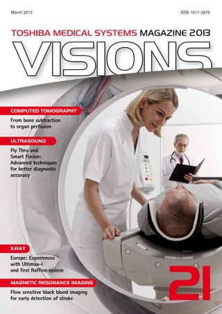
  • 1. ISSN 1617-2876March 2013 toshiba medical systems MAGAZINE 2013 21 From bone subtraction to organ perfusion COMPUTED TOMOGRAPHY Fly Thru and Smart Fusion: Advanced techniques for better diagnostic accuracy ULTRASOUND Europe: Experiences with Ultimax-i and first Raffine system X-RAY Flow sensitive black blood imaging for early detection of stroke Magnetic Resonance IMAGING
  • 2. TOSHIBAMEDICALSYSTEMS IMPRINT Imprint Publisher: TOSHIBA Medical Systems Europe B.V., Zilverstraat 1 NL-2718 RP Zoetermeer Tel.: +31 79 368 92 22 Fax: +31 79 368 94 44 Email: visions@tmse.nl Web site at: www.toshiba-medical.eu Editor-in-chief: Jack Hoogendoorn Modality coordinators: CT: Roy Irwan UL: Joerg Schlegel XR: Jaco Terlouw MR: Faiza Admiraal-Behloul Printing: WVD, Mörfelden-Walldorf, Germany Subscription Service: Email: visions@tmse.nl © 2013 by TOSHIBA Medical Systems Europe All rights reserved VISIONS 21 . 13
  • 3. VISIONS 21 . 13 EDITORIAL Dear reader, 3 Sharing my passion for and deep interest in Japan and having actively studied martial arts together for many years one of my closest friends accompanied me on a visit to an international exhibition dedicated to the samurai1; the military nobility of pre-industrial Japan. The exhibition brings together unique items from private collections and museums in Japan and throughout Europe. It reflects an interesting time when warlords, the Daimyo, fought each other by employing the services of fearsome samurai warriors and illustrates the highly developed warrior culture of that period. Walking through the museum, we were very impressed by the beautiful armor, spectacular helmets and magnificent swords that were deemed to reflect the ‘soul of the samurai’. Also on display were war banners, Nobori, from the Kitamura Collection, painted with family coats- of-arms and protective mythological figures, to identify the samurai on the battlefield. One particular Nobori showed a Koi Carp bravely climbing a waterfall. Legend states that once caught, the fish will lay on the cutting board awaiting the knife without a quiver. In Koi symbolism, this has been likened to a samurai warrior facing a sword. Ancient legend also said that a Koi that succeeds in climbing the falls is transformed into a dragon. Based on that legend, the Koi, at that time, was symbolic of worldly aspiration and advancement. The code of ethics, Bushido, imposed a lifestyle of honor, loyalty and respect within the warrior class. The samurai- elite devoted themselves with equal dedication to various arts such as calligraphy and the tea ceremony, and they wore delicately crafted accessories, including Netsuke and Inro lacquer work. A surprising element is the Dutch influence on the samurai warrior equipment, caused by the special bond between the two countries. Working close to a decade at Toshiba, I can proudly say that the same ethics, devotion and dedication is being applied daily to our product development and production, marketing and sales, service and support and above all, to the way we work together with our customers to provide integrated diagnostic solutions through long-term partnerships. We are committed to achieving the best in patient safe- ty across all modality products and it is our dedication and continuous mission to improve the overall quality of life of all people. Kind regards, Jack Hoogendoorn Sr. Manager Marketing Communications Toshiba Medical Systems Europe BV 1 Wereldmuseum Rotterdam, 11 October 2012 - 26 May 2013. E-mail: info@wereldmuseum.nl, Web: www.wereldmuseum.nl
  • 4. 4 Editorial President’s message M. Prokop Clearly Better – Toshiba’s Vision Edition Launched in Europe Case story Musculoskeletal Disorders: DSA-like Bone Subtraction with 320 Detector Row CT J. Hermans Whole Organ Perfusion of the Pancreas Using Aquilion ONE The first new generation Aquilion PRIME Breaking New Ground in Scanning Innovation E. Kotter Initial Clinical Experience with 3D Interventional Software Vital Images Vital Signs Landmark Deal with Skåne University Hospital F. Admiraal-Behloul Neuro-Microvascular Imaging at 1,5T Using the Flow Sensitive Black Blood Technique A ground-breaking partnership Toshiba Medical Systems joins Manchester United 3 30 6 9 12 16 20 22 26 32 Computed Tomography Advanced Visualization MRI Sports medicine This edition of VISIONS magazine is covering Toshiba’s European region and as such reflects products, technologies and services for that area. All mentioned products may not be available in other geopgraphical regions. Please consult your Toshiba representative sales office in case of any questions. VISIONS 21 . 13 CONTENTS With Toshiba’s newest and most advanced CT system, the AquilionTM ONE /Vision Edition, diagnosis goes faster and safer – Pages 6 and 12 Two experts in medical technology join forces – Page 22
  • 5. Ultrasound X-Ray News Events Raffine and Ultimax-i improve diagnostics and workflow in Russia and Scotland. Page 54 and 58 Two iconic brands come together: Toshiba supports Manchester United Football Club as its Official Medical Systems Partner – Page 32 VISIONS 21. 13 5 E. G. Grant Advanced Techniques in 4D Ultrasound: Fly Thru M. Filip, P. Linzer, D. Skoloudik Virtual Navigation – A New Modality in Perioperative Brain Tumor Imaging T. Fischer, A. Thomas, U. Bick Complementary Mamma Diagnostics to Characterize Focal Breast Lesions N. Azar Advances in Ultrasound: Smart Fusion Technology Europe’s first Raffine Russian Lung Specialists Refine Imaging With Toshiba System Experiences with the Ultimax-i Scottish Hospital Opts for Flexibility in X-Ray Meanwhile at Toshiba ECR 2013 The World of Imaging Meets in Vienna 36 41 44 50 54 58 63 66 CONTENTS
  • 6. VISIONS: Radboud University Medical Center is the first hospital in Europe to receive a new Toshiba Aquilion ONE Vision. What was behind the decision to choose the system? Prokop: I chose this system because of its superior image quality, fast rotation time, modified detector system and ultra low-dose capabilities. I thought Toshiba’s Aquilion ONE was a good machine that brought real advantages in both clinical practice and research, and as a next generation system, the Vision Edition offers even more benefits. As with Professor Mathias Prokop is one of the world’s lead- ing experts on body imaging. With a particular in- terest in new CT technologies, he has explored the boundaries of this modality for the last 25 years, heading many research institutes and projects worldwide. As Chairman of the radiology depart- ment at Radboud University Medical Center in ­Nijmegen, one of the Netherlands’ most well-known academic hospitals, he recently acquired Toshiba’s new ViSION Edition™ system for his multi-disci- plinary team. This state of the art system, which provides new clinical options through its faster ro- tation time, improved dose efficiency, wider bore and enhanced range of applications, is the first to be installed in Europe. VISIONS Magazine talked to Professor Mathias Prokop to find out more about his decision to invest in the new system and experi- ences with it since installation in July 2012. Clearly Better – Toshiba’s Vision Edition Launched in Europe VISIONS 21.13 COMPUTED TOMOGRAPHY 6 Professor Mathias Prokop and his team are happy to use the world’s most advanced dynamic volume CT system. Being able to view images instantaneously has a huge impact on our work. “ “
  • 7. and immediately accessible, affording us greater ca- pabilities in trauma and emergency care, cardiology and neurology, and the chance to carry out a wider range of perfusion techniques. With real-time con- struction of images we have far more scope to scan trauma and emergency patients and assess condi- tion quickly. The image subtraction feature on the Vision Edition is improved, offering us enhanced options in this method, which minimizes artifacts. The software capabilities with the new machine are amazing. The perfusion software is so flexible that we can jump to imaging other organs without inter- rupting the examination on one. The new system has good warping capabilities for scanning all organs. We have already achieved good results with imag- ing spleen and kidneys. Bowel imaging is currently not quite so straightforward, but we are exploring the possibilities with the Vision Edition. The new software for brain imaging is a unique, new feature. This is a particular interest of mine. Advances in CT imaging of the brain could be beneficial in work- ing with stroke patients, for example. We haven’t yet explored the 3D fluoroscopy capabilities of the machine but with the Vision Edition this is avail- able. Dose reduction is so effective that we are able to make CT scans using a dose range equivalent to that used for X-ray – a substantial reduction of up to 75%. VISIONS: How was training to use the ViSION Edition? Prokop: It was a very smooth transition into start- ing to use the new system as there is very little dif- ference in operation from the Aquilion ONE. There are no new operational issues and some things have even been made even easier and faster to use. its predecessor, we can scan all organs within one rotation. However, the gantry rotation is acceler- ated from 0.35 seconds with the Aquilion ONE to 0.275 seconds with the Vision Edition. This faster time opens up new possibilities for reducing the impact of image artifacts and improving image ac- curacy in cardiac imaging, for example, or pediat- ric or emergency investigations, in which it can be difficult to minimize movement of the patient, as well as enabling us to perform a broader range of perfusion examinations and increasing our work- flow. The ­Vision Edition has integrated Adaptive Iterative Dose Reduction (AIDR) 3D that enables us to achieve even lower dose scanning. Its wide, 78 cm bore set-up allows fast and easy set up for any type of clinical examination. In addition, I was able to work together with the Toshiba development team on certain issues when the system was in the final stages of development. I very much like to contribute to new things. I see this as a way of providing input into the future of CT. VISIONS: You worked quite extensively with the Toshiba team in Japan during development of the Vision Edition. What sort of issues were you involved in? Prokop: My collaboration involved developing a digital phantom to establish new standards for the machine and exploring the effect of varying many factors, such as the influence of different algorithms, the timing of the scan, filtering and sequence of dose variables. Through these investi- gations, we discovered some optimum calibrations for separate components. One particular interest that I have is exploring brain perfusion with the machine, since it is ideal for both research purposes and clinical practice, and I have been working with Toshiba on this too. VISIONS: Now that it is installed, what do you particularly like about the system? Prokop: The Vision Edition is altogether a very impressive scanner. There are many incremental improvements compared to the Aquilion ONE. The image quality achieved with the system is superior 7 Main entrance of the St. Radboud hospital I chose this system because of its superior image quality, fast rotation time, modified detector system and ultra low-dose capabilities. “ “
  • 8. VISIONS 21.13 COMPUTED TOMOGRAPHY research. Being able to view images instantaneously has a huge impact on our work. The system has already improved our workflow and we are able to use it for an increasing number of applications. We are able to use lower than ever doses and achieve higher patient- and consultant satisfaction. It also reduces our costs. VISIONS: How about the service you have received from Toshiba? Prokop: We are very happy with the excellent serv- ice we received from Toshiba’s team in Japan and Toshiba Medical Systems Europe in the Netherlands. As one of the first users of different generations of CT scanners, I am familiar with the risks involved in purchasing and installing new systems. I know what can happen and what the pitfalls are but in this instance, there were only very minor issues to work on. Overall, the collaboration during development, the added benefits of the new Vision Edition and the service package provided by Toshiba have been outstanding. VISIONS: Thank you. VISIONS: What comments have your colleagues made about the new system? Prokop: The trauma unit in particular has benefit- ted already from the speed of the Vision Edition and the extended range of high quality images that can be achieved. Even the upper extremities, for ex- ample, can easily be scanned in very short spaces of time. The emergency staff at the hospital continue to be amazed by the immediate diagnosis possi- bilities provided by the new machine. It is an ideal system for use in trauma and emergency care. Our neurologists are using the scanner for both regular neurological assessments and also advanced CT per- fusion techniques. They are exited about the image quality produced by the system. Our cardiologists can perform a broader range of examinations and are now using CT perfusion techniques, which they were not able to perform before. It has actually changed the way our cardiologists think about the use of CT in their field. I believe that CT will become the imaging modality of choice for an even wider range of diagnostics, and with the Toshiba Vision Edition I am able to convince my colleagues of this too. VISIONS: What difference has the system made to the radiology department in general? Prokop: The department serves a total of 18 resi- dent radiology specialists, is staffed by 30 employ- ees and is used to diagnose approximately 100,000 patients per year. The Vision Edition is a very wel- come addition to our two existing machines in the department. It is in constant use for a very broad range of applications from trauma and emergency care and a wide range of clinical applications to 8 In addition to having produced hundreds of scientific papers on lead- ing issues in body imag- ing, Professor Prokop is co-author of one of healthcare’s best known reference titles on CT techniques, Spiral and Multislice Computed Tomography of the Body, (ISBN 978-3-13- 116481-0 (TPS, Rest of World), ISBN 978-0- 86577-870-2 (TPN, The Americas), Mathias Prokop and Michael Galanski. The title is a worldwide bestseller and whilst the book was so advanced for its time that it still has perfect relevance today, a new edition is currently in the pipeline. Toshiba’s Aquilion ONE was a good machine that brought real advantages in both clinical practice and research. As a next generation system, the Vision Edition offers even more incremental benefits. ““
  • 9. 9 Paget‘s disease VISIONS 21.13ComputeD tomographY in MR calcium does not directly interfere with the visualization of the contrast media. The typical example of a non-lytic, enhancing bone anomaly with major diagnostic implications is the so called bone marrow edema pattern (BMEP). BMEP can be present in association with multiple tumors, inflammatory, degenerative and traumatic conditions and is composed of a mosaic of different histologic anomalies (fibrosis, trabecular thickening, cellular infiltration and to a lesser extent edema)1. BMEP invariably enhances and its identification is important for lesion characterization and may have significant prognostic implications which can directly influence patient management2. Normally BMEP is only seen on MR since the normal bone precludes the visualization of this anomaly on CT. DSA-like (Digital subtraction angiography) bone subtraction is a CT technique that allows removal of calcifications and bone (both cortical and trabecu- lar) without affecting the visualization of adjacent contrast enhanced structures. This technique allows the identification of contrast enhancement on CT of a non-lytic bone lesion and can be useful in vari- Introduction CT is a frequently used imaging method for the evaluation of bone lesions and densely calcified soft tissue musculoskeletal lesions. It elegantly demonstrates the lesion’s contours and the reactive changes of the bone and periosteum adjacent to it, features which are fundamental for lesion char- acterization. Some lesions however require further analysis to reach a conclusive diagnosis or narrow down the possible differential diagnosis. The intra- venous injection of contrast media is one of the most frequently used tools to help in the charac- terization of musculoskeletal lesions. On CT, enhancement after iodinated contrast injection is readily seen in lytic and non-calcified soft tissue lesions. The visualization of contrast enhancement in non-lytic bone lesions is however practically impossible with conventional CT tech- niques because the high density of trabecular and cortical bone obscures the visualization of the hy- perdense iodinated contrast. This represents one of the main advantages of MRI over CT for the evalua- tion of non-lytic or densely calcified lesions because Musculoskeletal Disorders: DSA-like Bone Subtraction with 320-Detector row CT P. Teixeira University Hospital (CHU) Nancy Radiology Department, Nancy, France Case 1 Focal lytic bone lesion with marked cortical thickening in an elderly patient Cortical enhancement has a similar density than the cortical bone and is taken away with classic bone subtraction With DSA bone subtraction the full extent of cortical enhancement is demonstrated. This patient has a biopsy proven focal Paget’s disease MRI T2FS X-Ray DSA bone subtraction Classic bone removal Why is it different?
  • 10. VISIONS 21.13 ComputeD tomographY 10 other hyperdense structures have been completely re- moved and only the enhanc- ing structures remain (Case 1 and 2). Image registration is at the heart of DSA-like bone subtraction. If the pre- and post-contrast volumes are not meticulously matched pixel by pixel, artifacts are intro- duced into the subtracted im- ages. Most of these artifacts are related to patient motion between the two acquisitions. Together with the greatly re- duced acquisition time pro- vided by current 320-detector row CT scanners (less than 0.5 s for the whole volume) the use of non-rigid registration algorithms can help overcome motion related artifacts. With the development of robust registration algorithms dedicated to the bone analysis, intra-osseous en- hancement can be confidently identified. Until now, this type of bone removal was not avail- able in clinical practice because the subtraction of conventional helical acquisitions is technically ­demanding and time consuming. 320-detector row CT scanners can image up to 16 cm in a single rota- tion of the X-ray tube using a sequential acquisition mode. Using this type of acquisition the subtraction of pre- and post-contrast volumes is simpler and faster. Similar to DSA, a pre-contrast volume (mask) is subtracted from a post-contrast one and after post-processing a new volume, in which only con- trast enhancement ­remains, is generated. Material and methods Dedicated bone subtraction algorithms were used for the evaluation of patients referred for CT imag- ing at our institution for the diagnostic work-up of suspected bone lesions. All CT images were acquired with a 320-detector row CT scanner (Aquilion ONE, Toshiba Medical Systems, Otawara, Japan) using a sequential scan mode before and after injection of iodinated contrast media. An iterative reconstruc- tion algorithm (AIDR 3D) was used and the tube output parameters (kV, mAs) were adapted to the patient body habitus in order to keep the exposure dose to a minimum. The images were then post-processed using SURESubtraction Ortho software. The subtracted im- ages were compared to conventional CT images and correlated to MRI when available. Selected cases that demonstrate the added diagnostic value of DSA-like bone subtraction are presented. ous clinical settings such as tumor characterization, tumor staging, occult fractures and inflammatory diseases. Additionally DSA-like bone subtraction can be performed with conventional CT protocols (pre- and post-contrast) as well as with dynamic CT perfusion. DSA-like bone subtraction offers a great advan- tage over conventional density-based bone subtrac- tion techniques on CT. In the latter methods the bone and calcification are segmented from the adjacent vessels and soft tissue based on their density and morphology. When there is intra-osseous enhance- ment there is no difference in morphology or in den- sity making it impossible to separate the bone from contrast enhancement. As a result, intra-osseous contrast enhancement is removed along with the bone with the consequent loss of important diag- nostic information. In this manuscript a description of the principles of this technique is provided along with examples of its clinical applications (Case 1 & 2). Basic principles As its name implies DSA-like bone subtraction uses the same principle of bone subtraction as used for interventional radiologic procedures. A mask for subtraction of the anatomic region to be studied is acquired before contrast injection. Contrast is then injected and the post-contrast image acquisi- tion is performed normally. During post-processing the two image sets are registered so that every anatomic structure corresponds exactly. Finally the registered image sets are subtracted. Since for X- ray based imaging methods calcium and metal are usually the only spontaneously dense structures to be found before contrast injection the result of the subtraction is an image set in which bone and Local staging of a lytic bone lesion, 64 year old female, Femur sarcoma MRI (T2 fat saturated sag) CT perfusion CT perfusion CT with DSA-like bone subtraction This lesion has three components: Soft tissue (arrowheads), lytic bone (thin arrows) and nonlytic bone (fat arrows). As expected MR imaging can depict all three components. In conventional CT perfusion, however the nonlytic component is not seen. With DSA-like bone subtraction enhancement is seen in the nonlytic areas of the bone, matching the enhancement seen on MR. This information has obvious importance in the surgical planning. Case 2
  • 11. 11 Clinical experience There are many potential clinical applications of DSA-like bone subtraction. From our experience this technique is particularly useful in the following clinical contexts: Identification of BMEP CT studies are often performed for the evalua- tion of osteomyelitis or spondylodiscitis, however structural bone anomalies and bone changes may not be present in the acute phase, precluding di- agnosis at this stage. In some clinical contexts, such as diabetic foot ulcers, decubitus ulcers, back pain and fever, the visualization of BMEP is highly predictive of intra-osseous spread of infection and has obvious implications for patient management. The presence of BMEP is also a key feature for the diagnosis of stress fractures and bone-on-bone impingement (osteochondromas, hypertrophic bone callus, wrist and ankle impingement syn- dromes). When conventional CT is inconclusive, a complementary imaging method, usually MRI or scintigraphy, has to be performed to reach diag- nosis3. The use of DSA-like bone subtraction algo- rithms can help identify areas of BMEP on CT scans which can expedite the diagnosis, since in many of these cases CT is the first evaluation method employed. The ability to detect BMEP on CT also increases the diagnostic possibilities when MRI is not available (pacemaker, cochlear implants, agi- tated or claustrophobic patients). Localization of occult bone lesions Multiple benign and malignant conditions may present as a non-lytic, non-sclerotic bone lesions which are not identifiable on conventional CT. The identification of an intra-osseous enhancing lesion is of significant clinical importance because this finding may be related to early metastatic disease or aggressive bone tumors. Although CT with bone subtraction is not a screening tool, CT is performed in a wide set of clinical situations and the ability to detect this type of bone lesion may be important for patient management. As with all current CT acquisi- tions, subtracted images can be reformatted in any plane, which in our experience offers a welcome aid in the planning and execution of CT guided bone biopsies. Characterization of lytic bone lesions Bone tumors occur frequently as non-specific lesions on imaging. The diagnosis in these tu- mors relies on invasive procedures (percutane- ous or surgical biopsy) for the histologic con- firmation of the lesion’s nature. Relatively few lytic bone lesions are known to be associated with BMEP on the adjacent bone marrow, which acts in these cases as a distinguishing feature. This is the case for osteoid osteomas, osteob- lastomas, chondroblastomas and eosinophilic granulomas4. DSA-like bone subtraction adds the possibility of using conventional CT to non- invasively diagnose these lesions, sparing the patient additional invasive diagnostic tests. Local staging of lytic bone lesions Aggressive bone lesions may demonstrate micro- scopic invasion of the bone adjacent to its margins. The non-invasive differentiation between tumor invasion and reactive bone change is difficult and sometimes impossible since both of these anoma- lies are associated with abnormal enhancement in non-lytic bone adjacent to a bone mass4. Accurate local staging is one of the cornerstones of curative surgical resection of bone tumors. DSA-like bone subtraction can demonstrate enhancement adja- cent to an aggressive bone lesion assisting in accu- rate local staging. Additionally this technique may have a potential role in association with other MR based imaging techniques in the characterization of peritumoral anomalies. Assist perfusion analysis (ROI placement) when performing CT perfusion of bone lesions With the major dose reduction offered by new de- velopments in CT technology, mainly related to bet- ter and larger detectors and iterative reconstruction algorithms, CT perfusion can now be used in a wider range of clinical applications. This is particularly true for the upper and lower limbs, where the tissue sensitivity to radiation is very low with a resultant low effective dose. CT perfusion of bone lesions can be difficult because of the adjacent high density bone. Although contrast enhancement in non-lytic bone is measurable on CT perfusion it cannot be seen. How can you measure something you cannot see? Where should you place the ROI? Bone sub- traction is of great assistance in these cases. Once subtraction allows the enhancing area to be visual- ized the ROI can be correctly placed increasing the accuracy of CT perfusion results. Conclusion The use of CT scanners with a wide detector design offers the possibility of DSA-like bone subtraction, which has many potential applications in the evalu- ation of musculoskeletal disorders. This technique helps locate, characterize and stage malignant and benign bone lesions. It also has an important role in CT perfusion of bone tumors, assisting in the selec- tion of the region to be analyzed. Enhancement in a non-lytic bone lesion may have major diagnos- tic implications and is currently evaluated by MRI. DSA-like bone subtraction increases the diagnostic power of CT in various clinical situations helping reach a conclusive or highly probable diagnosis for patients with musculoskeletal disorders. References 1 Blum A, Roch D, Loeuille D, Louis M, Batch T, Lecocq S, et al. [Bone marrow edema: definition, diagnostic value and prognostic value]. J Radiol. 2009 dez;90(12):1789-811. 2 Walsh DA, McWilliams DF, Turley MJ, Dixon MR, Fransès RE, Mapp PI, et al. Angiogenesis and nerve growth factor at the osteochondral junction in rheumatoid arthritis and osteoarthritis. Rheumatology (Oxford). 2010 out;49(10):1852-61. 3 Toledano TR, Fatone EA, Weis A, Cotten A, Beltran J. MRI evaluation of bone marrow changes in the diabetic foot: a practical approach. Semin Musculoskelet Radiol. 2011 jul;15(3):257-68. 4 James SLJ, Panicek DM, Davies AM. Bone marrow oedema associ- ated with benign and malignant bone tumours. Eur J Radiol. 2008 jul;67(1):11-21.
  • 12. on different models, i.e. maximum slope and patlak plot. These models have different requirements and produce different outcomes. The maximum slope is a linear approach which computes the perfusion values based on the maximum slope of the arterial time curve showing the arterial flow of the organ in ml/min/100ml. The Patlak plot relies on the back- flow of contrast medium from the extravascular to intravascular compartments. The exchange of con- trast between blood and tissue is then calculated on the Patlak plot, which uses linear regression to analyze contrast uptake in tissue. Patient history and diagnosis A 64-year-old man with vague abdominal pain was presented at our hospital after a transabdominal ul- trasound showed a hypoechoic mass of about 4 cm in the uncinate process of the pancreas. C-reactive protein, liver function tests, amylase, Hb and leuko- cytes were all within normal range. Because of this finding the patient was analyzed within a fast track protocol for workup of pancreatico-biliairy disease. After written informed consent was obtained the patient participated in a study on CT perfusion of the pancreas and liver. The CT perfusion images were registered and the tumor in the pancreas was subsequently analyzed according to the maximum slope model and the Patlak model. With both models a 4-5 cm mass was shown in the head of the pan- creas without obstruction of the common bile and pancreatic duct. The mass showed a large nonper- fused center. Towards the periphery of the tumor the perfusion gradually increased to normal pancreatic Introduction Aquilion ONE /Vision Edition, which has been intro- duced at the RSNA 2012, brings us a fundamentally new way to use a computed tomography (CT) scan- ner. With its fastest rotation time of 0.275 ms and z-coverage of 16 cm this state-of-the art scanner provides us and our patients with robust clinical solutions every time. Not only produces Aquilion ONE /Vision Edition the highest diagnostic image quality with the lowest possible radiation exposure it also offers new clinical solutions, like dynamic imaging and whole organ perfusion. This new CT scanner allows us to scan dynamically with uniform (xyz) temporal resolution of 137.5 ms and 16 cm volume coverage: from morphological to physiolog- ical diagnosis. Only few studies have been published about CT perfusion of the pancreas, partly due to the small volume of coverage with previous scanners. ­Aquilion ONE /Vision Edition makes it possible to scan an entire organ such as the pancreas. During free breathing of the patient multiple sequential time points are acquired to obtain a tis- sue concentration curve. The time interval between acquisitions is small in the arterial phase (circa 2 seconds), is larger in the parenchynal phase (circa 3 seconds) and increases to 1 minute in the late venous phase (Fig. 1). Because of movement of the pancreas in the z- axis during the acquisitions, the obtained high reso- lution perfusion images are registered with a sophis- ticated non-rigid algorithm, using one volume with maximal enhancement as a reference scan. Subse- quently, perfusion maps can be calculated based J. J. Hermans Whole Organ Perfusion of the Pancreas Using Aquilion ONE VISIONS 21.13 COMPUTED TOMOGRAPHY 12 Fig. 1: Time sequence protocol
  • 13. in the pancreatic head. FNA from the solid compo- nents demonstrated malignant cells belonging to a carcinoma of the pancreas. Comments Quantitative analysis of tissue microcirculation can possibly be used for biological characteriza- tion of solid pancreatic tumors and for evaluation of response to chemotherapeutic agents and-or radiotherapy. In the future perfusion parameters might be used to predict tumor aggressiveness and/ or to design an individually tailored therapeutic approach. tissue. For perfusion analysis of the liver a dual input model was used which showed a small hyperper- fused lesion of 5 mm in the caudate lobe and a small non-perfused lesion of 5 mm in segment six of the liver. On T2-weighted TSE and post-contrast MR images the lesion in the caudate lobe showed characteristics of a metastasis and the lesion in seg- ment six of a cyst. On MRI four more metastases in the liver cupola were detected. Because the pan- creatic tumor was positioned rather caudal in the pancreas, the liver could not be completely covered within the 16 cm dynamic volume. Therefore these metastases high in segment four and eight could not be analyzed for perfusion characteristics. Be- cause of the presence of liver metastases a curative resection of the primary pancreatic tumor was no longer feasible. To obtain a definitive diagnosis an endoscopic ultrasound (EUS) was performed which showed a multicystic mass with solid components 13 Max. slope Fig. 2: Two different models: maximum slope and Patlak plot Fig. 3: A small lesion in segment six of the liver with high signal intensity on a coronal HASTE image without contrast enhancement in the late venous phase, characteristic of a small cyst Patlak
  • 14. Fig. 6: Maximum slope model a) contrast-enhanced CT image of a large tumor in the pancreatic head. b) Perfusion map of the tumor with ROI1 in the central necrosis and ROI2 in the enhancing rim Fig. 4: Small lesion in the base of the caudate lobe with increased signal intensity on T2- weighted TSE with fat suppression image and rim enhancement in the late venous phase, characteristic of a metastasis VISIONS 21.13 COMPUTED TOMOGRAPHY 14 Fig 5: Shows the enhancement curve in the aorta (artery) and in the pancreas tail (tissue) 6a 6b
  • 15. 15 Fig. 7: Patlak graph before (a) and after (b) adjustment of start point (SP) and end point (EP) Fig. 8: Patlak model a: perfusion map of a large tumor in the pancreatic head with central necrosis (ROI 1) with a rim of enhancing tumor tissue b: perfusion map of the normal pancreatic tail (ROI 1) 7b 8a 8b 7a
  • 16. VISIONS: Why did you invest in the Aquilion PRIME? Nigel Lewis: It is an unusual situation in that we were acquiring the first new generation Aquilion PRIME CT scanner. The Bradford Teaching Hospi- tal Trust had already invested in an Aquilion ONE scanner in 2012 for St Luke’s Hospital. We really wanted a very high specification scanner that would efficiently and effectively execute a throughput of work across a wide variety of areas including cancer staging, MSK, cardiac CT, CTCs all the way Nigel Lewis is Clinical Services Manager and Head of Profession at Bradford Royal Infirmary, one of the UK’s most respected centres for radiology. The hospital has recently acquired an Aquilion PRIME CT scanner for his multidisciplinary team. The state-of- the-art technology installation means that Bradford Royal Infirmary becomes a world reference centre for the most advanced CT scanning equipment available today. VISIONS magazine travelled to Bradford to talk with Nigel Lewis and his team to find out more about the installation of the first new generation Toshiba Aquilion PRIME CT scanner and his team’s experiences with it, during and since installation in January this year. With the new Aquilion PRIME Bradford Royal Infirmary becomes a world reference centre for the most advanced CT scanning equipment available today Breaking New Ground in Scanning Innovation VISIONS 21.13 COMPUTED TOMOGRAPHY 16 Bradford Teaching Hospitals gains the first new generation Aquilion PRIME Nigel Lewis: “With regard to the technology we can’t compare it with anything else as its a new generation of equipment.” “ “
  • 17. also helps Toshiba in helping define future develop- ments of its scanning platforms. The ongoing support from installation onwards saw a team of five consultants from Toshiba in­ cluding the machine technicians, software ­engineers through to advanced neuro imaging. We were also very interested in the shuttle helical function for brain and future developments for body perfusion scanning. Ultimately, we were looking at spending a significant amount of money for the best technol- ogy available. We needed to ensure it was future- proofed for up to 10 years. What really caught our attention was its smaller footprint combined with its large diameter bore of gantry, which enhances the patients experience as they don’t feel so claustrophobic. Additionally the applications packages like InstaView and Hybrid View with fast reconstruction are easily integrated with our protocols and workflows. VISIONS: How closely did you work with the Toshiba team prior to, and during installation? Nigel Lewis: I think we have a very special rela- tionship with Toshiba. We have had a very positive experience previously with the installation of the­ Aquilion ONE at St Luke’s. Right from the very start, Toshiba Japan, together with the UK team were heavily involved in the installation, acceptance test- ing, setting up of protocols and from the outset of scanning procedures. We look at it going forward as a real partnership that helps us get the best out of the technology for the hospital and its patients, but 17 Jonathan Barber (left) and Nigel Lewis were really impressed about the system set up and installation “ Jonathan Barber: “We have been very impressed with the Aquilion ONE and believe that the Aquilion PRIME will develop our examination expertise even further.” “
  • 18. The Bradford Royal Infirmary, one of the UK’s most respected centres for radiology examinations that we cannot currently offer. We will realise real advances for brain perfusion, body perfusion and for some of the dual energy applications, like stone characterization, that we are planning to design with Toshiba’s help. Ultimately we’ll be able to complete a full scan, quickly and effectively and get the patient moving faster towards treat- ment and recovery. Anne Williams, CT Advanced Practitioner and Team Leader: The scanning and table movement is ex- tremely quick and the design is extremely intuitive, which means that our staff can get to grips with the best technology very quickly. We are increasing the number of patients per session and reducing contrast dose by at least fifty percent compared to previous scanners we have used. VISIONS: Finally, what are your hopes for the sys- tem over the next year? What results do you hope to achieve and how will you measure success? Nigel Lewis: We hope to demonstrate that the new Generation Prime has significantly contributed to our scanning capacity and the development of ad- vanced scanning protocols, whilst being mindful of the complexity of examinations and the patients experience through access to this new technology. We are also looking forward to seeing the staff training and development at the same speed of technology innovation, both for scanning applica- tions and for reporting. It will definitely raise our profile as a world reference centre and we’re looking forward to be- ing the first to see developments on the platform. We have a very good equipment base with our Aquilion PRIME and Aquilion ONE technology and look forward to continuing to develop our clinical service to the benefit of both the patients and staff. VISIONS: Thank you very much for your time. We look forward to catching up again to find out what the partnership achieves over the next year. and applications specialists on site throughout in- stallation and ‘going-live’ period. Jonathan Barber, Consultant Radiologist and ­Divisional Director for Clinical Support Services: It’s incredibly exciting. We have a very good relation- ship with Toshiba that is based on great experiences with the technology and the service and support. We’ve been very impressed with the Aquilion ONE and believe that the Aquilion PRIME will develop our examination expertise even further. VISIONS: What has impressed you about the system set up and installation? Nigel Lewis: Firstly, I think the installation was very impressive, the fact that it was a new scanner and the support that was made available to the Trust both in protocol design, selection and building and in the actual applications training for the staff. I think it’s over and above what we have experienced before. With regard to the technology, we can not com- pare it with anything else as it is a new generation of scanner. Aquilion PRIME will enable us to increase patient throughput and to develop our scanning capabilities with boby perfusion and dual energy capabilities. VISIONS: What benefits have been realized with the system in place? Nigel Lewis: Over the coming months our capacity will increase. The scanner is obviously faster than anything we have been used to so that will realise extra capacity and patient throughput. More im- portantly, we can actually plan forward and offer VISIONS 21.13 COMPUTED TOMOGRAPHY 18 “Anne Williams: “We are increasing the number of patients per session and reducing contrast dose by at least fifty percent.” “
  • 19.
  • 20. Department of Diagnostic Radiology University Hospital Freiburg, Germany Basic principles Toshiba supports three modes of CT fluoroscopy that cover a wide range of interventional procedures. 1. Continuous 3-slice fluoroscopy 2. One shot 3-slice scan 3. 3D interventional software Continuous 3-slice scan mode permits instrument tracking in real-time, much like conventional fluoroscopy. This mode is frequently chosen for biopsies of lesions that are prone to physiological movement. One shot 3-slice scan mode provides three consecutive images with full resolution and requires considerably less dose and thus less exposure for patient and staff. 3D interventional software provides an isotropic 0.5 mm single exposure volumetric scan of up to 16 cm and is displayed in MPR. This technology allows the accurate planning and tracking of the needle path in oblique and double oblique orientation with excellent spatial orienta- tion and excellent tracking targets with a low dose tech- nique. Introduction Due to its excellent low contrast and high spatial resolution CT has a long history of be- ing the modality of choice for complex biopsy procedures. While CT fluoroscopy (CTF), intro- duced by Toshiba in 1994, made procedures faster and safer the recent launch of 3D inter- ventional software is a further major advance in CT-guided biopsy techniques. Complex biopsies often require a needle approach which traverses through the scan plane, making needle paths more difficult to track. True 3D interventional software, made available on the Aquilion ONE, helps tackle even the most challenging biopsy procedures and thus offers real clinical benefits. Remark- ably enough low dose parameter settings can be maintained as the use of AIDR 3D is ac- companied by only a very minor penalty in reconstruction time. E. Kotter Initial Clinical Experience with 3D Interventional Software VISIONS 21.13 COMPUTED TOMOGRAPHY 20
  • 21. Case study A 78-year-old male with a spiculated lung mass in the supero-posterior por- tion of the left lower lobe presented for core biopsy. A low dose ultra-helical scan to localize the lesion was performed (Fig. 1) with the patient in prone position. In a next step the volume reconstruc- tion of the ultra-helical scan was loaded into the 3D interventional program and automatically displayed in MPR for plan- ning purposes. Fig. 2a shows that the le- sion is situated directly behind the 8th rib requiring an oblique approach through the 7th and 8th intercostal space (see Fig. 2b). A reduced scan range in 3D interven- tional software was used to track the needle path in orthogonal and oblique imaging planes. The needle was posi- tioned correctly in the lesion after only two exposures (Fig 3). A core biopsy was performed and his- tological analysis confirmed a lung car- cinoma. Initial clinical experience At our clinical institution, we schedule on average twelve biopsy procedures per week. Since the introduction of 3D in- terventional software we have noticed a remarkable reduction in the time it takes to perform most interventions. In addi- tion, interventional radiologists carry out the increasingly complex biopsy proce- dures with much more confidence. True 3D image display no longer requires us to create a 3D “mind’s eye” view of patient anatomy. Direct and accurate visualiza- tion is provided in axial, coronal, sagittal and oblique planes. The 3D interventional tool is now used exclusively for our CT interventions and has proven to be an excellent aid for our radiology residents to quickly gain confidence and expertise. Conclusion Toshiba’s 3D interventional software, available on the Aquilion ONE and Aquilion PRIME systems, offers real-life clinical advantages for interventional CT procedures. Examinations can be per- formed faster and with a higher degree of accuracy. Fig. 1: Ultra- helical scan of whole thorax to localize the lesion Fig. 2 a: Lesion is situated directly behind the 8th rib Fig. 2b: Oblique planning through the 7th and 8th intercostal space Fig. 3: Oblique reconstruction clearly showing the position of the needle in the periphery of the lesion 21
  • 22. The company’s VitreaAdvanced software forms part of Vitrea Enterprise Suite and combines best- of-breed 2D, 3D and 4D clinical applications and world-class services with a centralized solution for managing volumetric image data across the medi- cal enterprise all accessible via the Web.  The solu- tion offers advanced applications for cardiovascular, neurovascular and oncology, and offers integration with PACS in a few simple clicks. VitreaAdvanced addresses the challenges of managing multiple disparate advanced visualization systems and is designed to improve performance and productivity, ensure scalability and redundancy. The system does not require proprietary hardware, allowing users to utilize their existing infrastructure.  Skåne Univer- sity Hospital was attracted to the level of acces- sibility and performance offered by VitreaAdvanced. Vital Images also offers VitreaView, which is a universal viewer that provides physicians with uni- versal access through a simple intuitive user inter- face for patient imaging. It offers secure integrated access to imaging through EMR, EHR, or HIE and also enables access to images from disparate databases, providing one integrated universal viewer. Institu- tions deploying VitreaView provide standardization and access for medical professionals, enabling them Skåne University Hospital has emerged as one of the leading medical institutions in Scandinavia, a repu- tation enhanced through the bold and innovative step to merge the two university hospitals of Malmö and Lund under one management team. This decision, taken by the regional council late in 2009, has enabled Skåne University Hospital to move forward in offering ground-breaking medical care and innovation to the population of Sweden it serves. One area where the hospital is at the forefront of care is in radiology, diagnostics and imaging, with its use of the latest technology and systems. That took on a new dimension recently with the hospital becoming a landmark customer for an im- portant global healthcare IT provider. Vital Images, a Toshiba Medical Systems Group Company and leading provider of advanced visu- alization and analysis solutions for physicians and healthcare specialists, signed Skåne University Hos- pital Malmö as its 5,000th healthcare IT and ad- vanced visualization solutions customer. With software utilized in hospitals in more 100 countries, Vital is now supplying solutions to Skåne University Hospital to help enhance the patient ex- perience across the region of Skåne. Lars Bååth, Associate Professor at Skåne University Hospital Malmö meets with Satoshi Tsunakawa, President and Chief Executive Officer, Toshiba Medical Systems Corpora- tion and the Toshiba Team at RSNA. Vital Signs Landmark Deal with Skåne University Hospital VISIONS 21.13 ADVANCED VISUALIZATION 22
  • 23. 23 to optimize their time and focus on patient care. Institutions deploying VitreaView provide stand- ardization and access for medical professionals, en- abling them to optimise their time and focus on pa- tient care. It was this level of accessibility and perform- ance which attracted Skåne University Hospital to the company. Lars Bååth, Associate Pro- fessor and head of the clini- cal department for radiology at the hospital, said: “Skåne University Hospital Malmö made the decision to pur- chase the Vital solution after months of thoughtful con- sideration and evaluation of all the leading solutions in the market. “We are confident that the solution will ex- ceed the requirements we set forth and look forward to a meaningful partnership with Vital.” The solution Skåne University Hospital has pur- chased which will facilitate post-processing of 4D angiography of cerebral vessels; easy and automat- ed post-processing of CT perfusion of the brain; and easy volume measurements such as measurement of the volume of cerebral haemorrhages and infarc- tions as well as brain tumours. Professor Bååth said a major factor in choosing the Vital solution was because the system afforded “the possibility of different post-processing that are almost automated, rapid and easy to handle.” He added: “As we purchased the Vitrea licenses incorporated in our PACS, it enables us to pick up the patient in question from PACS at any work station in the department, perform the post-processing and save snapshots, batches or videos and send them to PACS for presentation at clinical conferences. “It enables us to perform different measurements and analysis within the system such measurements of different cerebral blood perfusion parameters, degree of internal carotid artery stenosis, and evalu- ation of plaque morphology.” He said because the solution offers automated/ semi-automated post-processing software that is easy, logical and robust, it will save the radiolo- gists time, especially in an emergency situation that needs rapid decision making. Patients will also benefit from the rapid delivery of radiology reports as the post-processing is ex- tremely easy and automated. “It also enables measurements of values our available system do not offer e.g. absolute values of cerebral blood flow,” added Professor Bååth. Vital is equally delighted to be partnering Skåne University Hospital and see the institution becomes its 5,000th customer. Erkan A. Akyuz, president and chief executive officer at Vital, said: “We’ve had many notable milestones since Vital’s inception in 1988, including introducing one of the first ever advanced visualiza- tion solutions to the market and, more recently, the notable Toshiba acquisition last year. “Partnering with our 5,000th customer is a mile- stone we are particularly proud of, as it reflects the adoption of the solutions we develop as well as the commitment our employees have to customers and their patients.” Vital continually invests in programs and tech- nology designed to enhance relationships between customers, referring physicians, partners and pa- tients. Building on its knowledge and understanding of complex clinical workflow, Vital offers a compre- hensive suite of enterprise-wide advanced visualiza- tion and connectivity solutions. The merger of the two university hospitals in Malmö and Lund came into effect on January 1, 2010, enabling the strengthened clinical research and the university healthcare service in Skåne to gain increased competitiveness from a Swedish and international perspective. The hospitals in Lund and Malmö have a long his- tory and have been operating side by side since the latter part of the 19th century. The infirmary in Lund,
  • 24. VISIONS 21.13 ADVANCED VISUALIZATION which is one of the country’s oldest hospitals, was established as early as 1768. Both hospitals started off with a few beds and then grew in size over the years to meet ris- ing patient demand. Research and training are im- portant elements of what goes on at Skåne University Hospital, which is the third largest of Sweden’s seven university hos- pitals. Its three cornerstones are advanced medical care; training; and prominent research and it has one of the larg- est emergency medicine hospitals in Sweden. Major investments have been made in the hospi- tal campuses in Malmö and Lund in recent decades, which have created an excellent environment for research scientists, students and care personnel. Questions and experience from meetings with patients at the clinic are brought into the laboratory with the research results fed back to the patients in the form of new improved methods of diagnosis and treatment, new drugs and new techniques. 24
  • 25. Skåne University Hospital’s key milestones The year 1768 saw the foundation of the Lund In- firmary and in 1857 Malmö’s general hospital in Slottsgatan was established, with an annex at Jakob Nilsgatan. In 1948, the Swedish government agreed to allow Malmö General Hospital to carry out clini- cal teaching. In 1989 the Medical Research Centre (Lund Uni- versity) was inaugurated and in 1993 the Lund In- firmary changed its name to University Hospital in Lund while Malmö General Hospital (MAS) changed its name to the University Hospital MAS in 1994. In 2004 the Diagnostic Centre – one of the world’s most modern departments for medical imag- ing, was established in Malmö, in 2006, there was the inauguration of the CRC, the Clinical Research Centre (Lund University) building and in 2008 Re- gion Skåne’s Competence Centre for Research (RSKC) formally opened, creating new opportuni- ties for advanced research on the basis of a central biobank department. Meanwhile, 2010 saw the merger of the Univer- sity Hospital in Lund and the University Hospital in Malmö to form Skåne University Hospital and in 2012 Skåne University Hospital became the 5,000th healthcare IT and advanced visualization solutions customer for Vital. The 780-bed Skåne University Hospital has 11,700 employees, with an annual budget of SEK 10 bil- lion. On an average day at Skåne University Hos- pital: 24 children are born; 350 patients visit its two emergency departments; 151 patients have surgery; there are 1,327 inpatients; 915 patients are X-rayed; six scientific articles are published; and SEK 28 million are consumed. Its radiology department carries out about 400,000 diagnostic exams a year, the lion’s share of the 900,000 radiology examinations conducted annually by the 10 hospitals of the region. Within the Skåne region today, there is a unity in the equipment that the hospitals’ radiology de- partments use. All access the same and have imple- mented a cross-enterprise solution for distributed radiology cooperation within and outside the region independent of the supplier of RIS or PACS. By linking the hospitals’ radiology operations in a single shared RIS/PACS solution, an efficient flow of images and information was created throughout the region. Its infrastructure supports automatic sharing and distribution of radiology information to all de- partments involved in the radiology workflow. With the latest partnership with Vital, Skåne University Hospital is moving its care in radiology, diagnostics and imaging onto yet another level. 25
  • 26. LSA branches can be clearly observed using dig- ital subtraction angiography, though this tech- nique is invasive. Recently, LSA branches have been successfully visualized with 7T MR imaging by using time-of-flight MRA1,3. Some relation- ships between decreased LSA visualization and hypertension or infarction at the basal ganglia and/or its vicinity were demonstrated3. However, the availability of 7T MR imaging systems is very limited, and they are currently used for research purposes only. There is a great need for imaging the mi- crovasculature in the brain for the early de- tection of cerebrovascular strokes in routine clinical practice and for research purposes. However, the literature agreed that non-in- vasive imaging of cerebral microvascula- ture such as the LSAs requires ultra-high MR field strength (7T) and could not be real- ized at lower field strengths (1,5T nor 3T)1-3. Introduction Cerebral magnetic resonance angiography (MRA) at 1.5T is generally limited to the time-of-flight (TOF) technique which is most widely used for the visualization of macrovasculature in intracranial ­arterial diseases. The TOF technique at 1,5T has spa- tial and contrast resolution limitations for visual- izing slow-flow arterial branches mainly because of spin ­saturation and relatively short T1. Current neuro-imaging techniques based on computed tomographic angiography or digital sub- traction angiography have been used to investigate vascular pathophysiology. However, the study of microvascular diseases in vivo has been restricted by their inherent invasiveness. Lenticulostriate arteries (LSAs) are one of the most important microvascular structures in the hu- man brain as they supply blood to the basal ganglia (Fig. 1) where ischemic and hemorrhagic cerebral strokes often occur. The LSAs are end arteries that have little or no collateral circulation. Neuro-Microvascular Imaging at 1,5T Using the Flow Sensitive Black Blood Technique F. Admiraal-Behloul VISIONS 21.13 26 MRI Toshiba Medical Systems Europe, Zoetermeer, The Netherlands Fig. 1: Lenticulostriate Arteries anatomy. The horizontal M1 segment gives rise to the (lateral) lenticulostriate arteries which supply part of head and body of caudate, globus pallidus, putamen and the posterior limb of the internal capsule. Often the medial lenticulostriate arteries arise from the A1-segment of the anterior cerebral artery. Faiza Admiraal-Behloul
  • 27. A shorter TE value (~20ms) and a lower b-factor would minimize the T2* effect and be more favora- ble to arterial imaging while minimizing the venous/ parenchyma contrast allowing a better artery/veins discrimination (see Fig. 3). The common imaging pa- rameters are TR=29 msec, TE=20 ms, flip angle=20°, MPG pulse b-factor= 2 s/mm2 acquisition matrix size=256 x 224, FOV 205x179 mm in one axial 3D slab of 160 slices. The scan resolution was 0.8 x 0.8 x 0.8 mm (reconstructed into 0.4 x 0.4 x 0.4 mm in order to increase apparent resolution) for a scan time of ~6,5 minutes. Clinical evaluations T. Kodama and co-authors6 from the university of Miyazaki (Japan) compared FSBB to SWI in the visualization of venous malformation (VM), arterio- venous malformation (AVM) and dural arteriovenus festulas (dAVF) using a 1.5T Vantage ZGV Atlas. They showed that VMs were more clearly visualized on FSBB images than SWI. They found that small VMs could be missed on SWI images. In some cases, por- tions of draining veins could not be clearly visual- ized on SWI images. Their findings suggested that direction of vessels in respect to that of the mag- netic field affected their visualization on SWI im- ages. Furthermore, they found that drainage veins of AVMs and dAVFs can be hyperintense on SWI im- ages probably because of their arterialization due to the arteriovenous shunt. Even though SWI has flow compensation, feeding arteries sometimes showed signal loss. On FSBB images, all of arteries, niduses, veins, and hemorrhagic lesions appeared as “black” structures. In five patients with AVM or dAVF, prom- inent venous structures other than drainage veins were clearly noted on FSBB images. These veins seemed to reflect hemodynamic changes such as venous congestion, collateral circulation, and steal phenomenon associated with the AVM and dAVF. Flow sensitive black blood imaging FSBB is a high resolution 3D gradient echo tech- nique which, unlike Susceptibility Weighted Imag- ing (SWI), uses a weak Motion Probing Gradient (MPG) pulse that dephases the water signals of the flowing blood and has no effect on the water signal in stationary tissues4,5. SWI is based on high resolution, three-dimen- sional (3D), fully velocity-compensated gradient- echo sequences using both magnitude and phase images. A phase mask obtained from the MR phase images is multiplied with magnitude images in order to increase the visualization of the smaller veins and other sources of susceptibility effects. The im- ages are then displayed using the minimal intensity projection (minIP). Because the image contrast in SWI is mainly based on the susceptibility effect SWI is more successful at high (3T) and ultra-high (7T) field strengths. Furthermore, phase disturbance is observed mainly in the vein and therefore not suit- able for arterial microvasculature imaging. With FSBB the signal from rapidly flowing blood is attenuated by applying a very weak MPG for sig- nal dephasing, which mainly attenuates the signal from rapidly flowing blood in the artery, while the signal from stationary or slow-moving components is not or much less affected. Since this technique does not rely only on susceptibility effect only, it can be successfully used at standard (1,5T) field strength (see Fig. 2). Being a 3D gradient echo technique, FSBB can, like SWI, benefit from the susceptibility effect use- ful for venous signal visualization. When a long TE value is used (~40 ms) the T2* effect is increased and the venous signal is attenuated which allows a good contrast with the parenchyma. The typi- cal parameters for susceptibility oriented FSBB are: TE: 40 ms, TR: 50 ms, FA: 20, MPG pulse b-factor= 4 s/mm2 acquisition matrix size=256 x 224, FOV 205 x 179 mm in one axial 3D slab of 160 slices. The scan resolution is 0.8 x0.8 x 0.8 mm (reconstructed into 0.4 x 0.4 x 0.4 mm in order to increase apparent resolution) for a scan time of ~6,5 minutes. 27 Fig. 2: Comparison between minIP SWI image (left) and minIP FSBB image (right) in a healthy volunteer scanned at 1.5T. Note the increased vessel/parenchyma contrast in FSBB.
  • 28. 28 in terms of number, length, and image quality at ori- gins and distal areas of visualized LSA branches. In all evaluated terms, FSBB was significantly better than TOF. In a very recent study S. Okuchi and co-authors10 from Kyoto University Graduate School of Medi- cine, Kyoto (Japan), ex- amined the correlation of LSA imaging findings using FSBB in patients with la- cunar infarction compared with age matched con- trols. They prospectively enrolled fifteen patients (9 men, 6 women, mean age 73 years) with infarction at the basal ganglia and/or its vicinity, and 12 age-matched control subjects (6 men, 6 women; mean age, 68 years). The authors found that patients with stroke had significantly fewer LSA branches (average 6.3; 95% CI, 5.4–7.1) than controls (8.7; 95% CI, 7.8 –9.5) (P=.0003). The total LSA lengths were 117 mm (95% CI, 96–138 mm) for patients with stroke and 162 mm (95% CI, 133–91 mm) for control subjects (P=.01). Only the LSA branch numbers were significantly related to infarction while only hypertension was signifi- cantly related to total LSA length. Discussion and future work Microvascular brain damage is mainly assessed by imaging the microbleeds (MB) and not by studying the microvasculature itself as this was not possible in-vivo at clinical MR field strength (≤3T). However, at ultra-high field strength (≥7T) it has recently be- V. Sawlani and co-authors7 from Morriston and Singleton hospitals ABM university NHS trust (UK), showed the potential of the FSBB technique on a 1.5T Vantage XGV Atlas system in several cerebral vascular diseases: FSBB was found a useful tool in imaging hemorrhages from trauma, visualizing blood products, venous sinus thrombosis but also in neuro-oncology (see Fig. 4). The microvasculature and hemorrhage of the tumor could be depicted with FSBB. These findings demonstrate the potential of FSBB in tumor grading and in therapy monitoring. K. Gotoh and co-authors from Kyoto University Graduate School of Medicine, Kyoto (Japan), com- pared FSBB to TOF in the visualization of the LSAs in 21 healthy subjects (age range 19-44 years)8,9. They found in9 a total of 145 LSA branches visualized with FSBB while only 66 branches were visualized with TOF. All the LSAs visualized with TOF were also visualized with FSBB. The images were evaluated VISIONS 21.13 MRI Fig. 3: FSBB image (minIP) clearly showing the LSAs (yellow arrows) at 1,5T field strength in a healthy volunteer Fig. 4: Primary glioma with hemorrhage. (a) Flair image (b) minIP FSBB image showing complex microvasculature of the tumor (Courtesy of Dr V. Sawlani, Morriston and Singleton hospitals ABM University NHS trust) A B
  • 29. 29 Toshiba is continuously working on further optimi- zation and innovation in cerebrovascular imaging13. Exiting clinical studies are taking place at luminary sites and more clinical evaluations of these innova- tive techniques are to be expected. References 1 Cho ZH, Kang CK, Han JY, et al. Observation of the lenticulostriate arteries in the human brain in vivo using 7.0 T MR angiography. Stroke 2008;39:1604–06 2 Kang CK, Park CW, Han JY, et al. Imaging and analysis of lenticu- lostriate arteries using 7.0-Tesla magnetic resonance angiography. Magn Reson Med 2009;61:136–4 3 Kang CK, Park CA, Park CW, et al. Lenticulostriate arteries in chronic stroke patients by 7 T magnetic resonance angiography. Int J Stroke 2010;5:374–80 4 Kimura T, Ikedo M, Furudate N, Takemoto S. Flow-sensitive suscep- tibility-weighted imaging. In: Proc Joint Annual Meeting, ISMRM- ESMRMB, Berlin; May 19–25, 2007:3015. 5 suchiya K, Tateishi H, Yoshida M, et al. Flow-sensitive susceptibility- weighted imaging of the brain: initial experience in ischemic lesions. In: Proc Joint Annual Meeting ISMRM-ESMRMB, Berlin; May 19–25, 2007:3016. 6 Kodama T, Yano T, Tamura S, et al. Flow-sensitive black blood imag- ing for evaluating vascular malformations. In: Proceedings of the 17th Annual Meeting of ISMRM, Toronto, Canada, 2008. (abstract 3425). 7 V.Sawlani, J. Spark, F. Admiraal-Behloul , Flow-Sensitive Black Blood Imaging : Clinical Intracranial Applications, In: Proceedings of the 20th Annual Meeting of ISMRM, Stockholm, Sweden, 2010. (ab- stract 2263). 8 Gotoh K, Okada T, Miki Y, et al. Visualization of the lenticulostriate artery with flow-sensitive blackblood imaging in comparison with time-of-flight MR angiography. In: Proceedings of the 17th Annual Meeting of ISMRM, Toronto, Canada, 2008. (abstract 2893). 9 Gotoh K, Okada T, Miki Y, et al. Visualization of the lenticulostri- ate artery with flow-sensitive black-blood acquisition in compari- son with time-of-flight MR angiography. J Magn Reson Imaging 2009;29:65–69 10 Okuchi S, Okada T, Ihara M, et al. Visualization of Lenticulostriate Ar- teries by Flow-Sensitive Black-Blood MR Angiography on a 1.5T MRI System: A Comparative Study between Subjects with and without Stroke. AJNR Am J Neuroradiol. 2012 Oct 11. [Epub ahead of print] 11 Kimura T, Ikedo M, Takemoto S. Hybrid of opposite-contrast MR an- giography (HOP-MRA) combining time-of-flight and flow-sensitive black-blood contrasts. Magn Reson Med. 2009 Aug; 62(2):450-8. 12 Tsuchiya K, Kobayashi K, Nitatori T, et al. Hybrid of opposite-contrast MRA of the brain by combining time-of-flight and black-blood se- quences: initial experience in major trunk steno-occlusive diseases. J Magn Reson Imaging. 2010 Jan; 31(1):56-60. 13 Kimura T, Ikedo M, Takemoto S. Phase enhancement for time-of- flight and flow-sensitive black-blood MR angiography. Magn Reson Med. 2011 Aug; 66(2):437-47. come possible. Therefore, there is a growing interest in studying the microvasculature in small vessel dis- ease and neuro-degenerative disease, during life, at ultra-high field. Unfortunately, ultra-high field MR scanners are still research systems not cleared yet for clinical routine use. Therefore 7T MR systems are not widely available; making it difficult to run large scale (multi-center) clinical studies at present time. FSBB is a new MR angiography technique that allows the visualization of the cerebral microvascu- lature at clinical MR field strength (1,5T and 3T). This technique is made available to the wider research community and can benefit all patients having ac- cess to standard clinical MR scanners. The FSBB technique was successfully used at 1.5T to visualize the microvasculature of AVMs, brain tumors, and even lenticulostriate arteries in healthy volunteers and stroke patients. It is a promising technique and the increased spatial resolution at 3T, down to 0.3 mm or less (see Fig. 5) opens the way to new clinical applications such as small vessel and/or degenerative diseases (vascular dementia, Alzheimer’s diseases, Multiple sclerosis, etc.). Toshiba has recently proposed a hybrid version11, called Hybrid Opposite contrast MRA, combining both TOF and FSBB is a dual echo 3D gradient echo technique for a bright blood visualization of the microvasculature. K. Tsuchiya and co-authors from Kyorin University Faculty of Medicine,Tokyo (Japan), showed in their initial experience a great potential of this technique for the visualization of collateral micovasculature in major trunk steno-occlusive dis- eases12. Fig. 5: FSBB images (minIP) acquired on Titan 3T. Note the increased spatial and contrast resolution.
  • 30. “Minimize. Visualize”. An Approach to Reaching the Next Level in Patient Care VISIONS 21.13 President’s Message 30
  • 31. doses and clearer images for the benefit of patients. One physician has applied this technology to facial transplant surgery in order to improve the quality of life of patients who have “lost” their faces in terrible accidents. The high spatial resolution of our CT systems makes it possible to visualize the small vascular details that are essential in surgery to restore normal facial movements. A patient who was desperate to undergo facial transplant surgery after suffering with “no face” for 18 months, made a remarkable recovery. This patient’s ability to make facial expressions was restored, making it easier for the patient to reintegrate into society. Our techno­ logy helped to make this possible. With regard to X-ray, we introduced our Spot Fluoroscopy technology in the previous issue of this magazine. Spot Fluoroscopy has been widely accepted by both practitioners and patients. It has been calculated that this unique dose reduction technology developed by Toshiba can provide re­ duction in both scattered dose and area dose dra­ matically. This is extremely useful for minimizing exposure during atrial fibrillation ablation proce­ dures. Again, this is one of the ultimate expressions of “Minimize, Visualize.” Finally, Toshiba has been selected as an offi­ cial medical systems partner of Manchester United in England. It is a very competitive process to be named an official partner of this illustrious club, and we are looking forward to Man U’s continued success in the future. I deeply value our relationships with our part­ ners and customers, and it is our customers who will contribute the most to Toshiba’s future growth. I am sure that our customers will continue to be the most valuable asset of our company. Satoshi Tsunakawa President and Chief Executive Officer Toshiba Medical Systems Corporation For the past several years, we at Toshiba have been involved in system development work to further improve accuracy and workflow efficiency in each modality. Progress has been remarkably fast, but our team realized that in order to reach the next level we must place even greater emphasis on patient care. Our overall global key message is “Improving the quality of life, for patients, for practitioners, for all people.” This reflects our policy of taking that extra step in customer care. In the previous issue of ­VISIONS, my message was that Toshiba is now expanding its focus to include the care of all people. At this time, we are especially focusing on the con­ cept of “Minimize. Visualize.” Our goal is to dem­ onstrate that we are a vendor that can continue to develop high-quality imaging technologies to ensure accurate diagnosis and treatment with the lowest possible exposure dose. Let me now intro­ duce some of the advances that have been achieved in each modality. With regard to MRI, the abstract for the REACT study has been accepted for presentation at ECR 2013. Toshiba Medical Systems Corporation (TMSC) is sponsoring a multi-center trial known as the RE­ nal Artery Contrast-free Trial (REACT). According to Dr. Timothy Albert, who is the leader of the REACT project, Time-SLIP, which is one of Toshiba’s non- contrast MR angiography (NC-MRA) techniques, will become a reasonable alternative for assessing renal artery stenosis (RAS) and also for evaluating patients with renal dysfunction who cannot receive contrast agents. I am very proud that we are able to supply our cutting-edge technology in accordance with our new concept, “Minimize, Visualize.” In ultrasound, we have developed Luminance technology. The objective of this technology is, of course, to achieve better image quality, and it is especially useful for visualizing the fetus. This 4D technology provides “Picture Perfect” images, al­ lowing expectant mothers to see the faces of their unborn children more clearly than ever before. In CT, as you already know, we have successfully incorporated AIDR 3D technology into all of our CT systems. This technology ensures extremely low 31 Minimize. Visualize.
  • 32. Toshiba’s executive team at the Old Trafford ground, including football stars Giggs, Kagawa and Nani Photographs by Paul Cooper As Toshiba Medical Systems enters a partnership with English Premier League side Manchester ­United to provide state-of-the-art medical equip- ment at the club’s training ground, team doctor Steve McNally outlines the benefits. The ground-breaking partnership between Toshiba Medical Systems and Manchester United is set to add a whole new dimension to the treatment the club’s medical staff can offer to players. In becoming the club’s Official Medical Systems Partner, Toshiba will provide the football club with a CT scanner ca- pable of single rotation volumetric imaging, an MRI scanner and five ultrasound systems including the industry-leading premium Aplio 500. Club doctor Steve McNally said the installation at the club’s Trafford Training Centre in Carrington would provide medical staff with improved diagnos- tic and screening tools that offer greater degrees of accuracy. This will allow them not only to monitor healing in injuries and fine-tune rehabilitation processes but also to identify potential injuries and respond to them before they become serious. In addition, it will offer the players more privacy and increased confidentiality when they are injured or ill and avoid the need for them to attend private facilities off-site. Dr McNally said: ‘We’ve always been fortunate to enjoy good access to imaging facilities in the Toshiba Medical Systems joins Manchester United VISIONS 21.13 SPORTS MEDICINE 32 locality, but having such equipment on site will be much more convenient and less disruptive in terms of affecting training and rehabilitation programs. The convenience also means that we will have a better opportunity to use imaging as part of our daily routine. It means more privacy, increased con- fidentiality, and a much better experience for the players as patients.’ He said another benefit of having the equipment available to the club’s medical team at Carrington is that medical staff will be able to discover more about just what the different medical imaging mo- dalities can do for them. ‘We’ll find out which sys- tems are most appropriate at certain times: what is normal, what is abnormal, and what is happening in the evolution of an injury. We can monitor healing in various injuries much more closely.’ The club already operates a comprehensive play- ers screening program, which includes undertaking detailed medical histories and clinical examinations in conjunction with functional tests, physical tests and some medical imaging. ‘But we could start to utilise these imaging tools to look in much more detail at the anatomy of play- ers; before they start pre-season training, what it is like after a certain phase of pre-season training, and what happens as they are exposed to the training loads and the game loads throughout the season,’ Dr McNally explained.
  • 33. radiation doses opens up a wider opportunity to use CT as a monitoring tool.’ With MRI, the distinct advantage of the 3-Tesla is speed of imaging and higher resolution, particularly in joint injury. ‘The increased detail and the facility to map the cartilage in joints over time will hopefully assist us in terms of the welfare of our players, but also it will allow us to assess the effects of our training programs on their joints,’ Dr McNally added. However, he be- lieves the biggest long term benefit from the Toshiba partnership will be in the field of injury prevention by detecting early pathological signs that would trigger a managed response long before they become acute or career-threatening injuries for players. Manchester United midfielder Ryan Giggs is equally excited about the partnership. ‘It’s fantastic to have such state-of the-art equipment at the train- ing ground. It means that having scans or medicals will be much more convenient as everything is there and to hand.’ Giggs, who is 39 and still a regular first team player, joined the club as a schoolboy when the medical team was smaller and access to advanced medical equipment and physiotherapy was limited. With the additions at the Carrington training ground, he added: ‘It’s no surprise that United are working with Toshiba Medical Systems and will have the latest equipment, such as MRI and other scanners, on site.’ ‘So, we can build a more detailed profile of what happens to the joints, the muscles, the ligaments, the tendons, the heart, the lungs and what effects the training program is having on those tissues and ­organs.’ Such medical scanning equipment offers the op- portunity to build complete medical profiles of play- ers and enhances monitoring of them as they develop and age; from the youngest players at the club who are only eight years old to those in their late 30s such as Ryan Giggs, Paul Scholes and more recently goalkeeper Edwin van der Sar, who was 40 when he stopped playing. From this, there will also be benefits for Toshiba, which will gain greater insights into sports medicine. The partnership is the first of its kind in the UK with a football club and Dr McNally believes the Toshiba equipment provided to the club’s medical team would help with the accuracy and speed of diagnosis of an injury leading to greater confidence in the treatment plan by both the patient and the treating clinician. ‘In combination with our expertise and experience it allows us to inform our coaches and our team man- ager with a timely and likely prognosis so they can plan for the team and we can plan strategies around the whole injury scenario - not just deal with the indi- vidual patient,’ he said, adding: ‘I think we could also utilise the systems to fine-tune our rehabilitation processes because we can monitor the progress and the evolution of tissue healing alongside the observed functional improvements.’ ‘That will give us greater confidence in making a certain progression in a rehabilitation program and also what types of exercise and loading we put on a player during that rehabilitation.’ Levels of radiation exposure have always been a consideration with CT scanners but Toshiba CTs are renowned for having very low radiation exposure, al- lowing its potential use as a screening modality. Dr McNally said: ‘The fact that the Aquilion sys- tems are well-known for having significantly reduced Mark Holmshaw, Toshiba’s Vice President Sales and Service Europe, is hopeful to introduce plans for screening and early diagnosis. Manchester United club doctor Steve McNally believes the biggest long-term benefit from the new equipment will be through the early detec- tion of patho- logical signs to prevent injury. Chikao Kamijima, President & CEO of Toshiba Medical Systems Europe, shakes hands with Sir Alex Ferguson, Manchester United, to confirm the partnership. 33
  • 34.
  • 35.
  • 36. Professor and Chairman, Department of Radiology, University of Southern California, Keck School of Medicine moving the observer’s eye according to the center line of the blood vessel, intestinal tract, mammary duct or any other fluid-filled structure in the body. In this ”auto“ mode, the system passes through the tubular structure while deciding automatically which branch to follow, for example, through the branches of the portal vein. The second option is conducting manual Fly Thru navigation, which is useful depending on what is being imaged. In manual mode clinicians direct the arrow, or perspective line of sight, through the structure. For example, in manual naviga- tion when viewing a bifurcating vessel, there is the ability to choose which of the two vessels to interrogate. Likewise, when looking at a polyp in the endometrium, clinicians can view from behind it and investigate another perspective. These two options for both automatic and manual mode provide flexibility in using Fly Thru for various ­clinical applications. In addition to automatic and manual visualiza- tion modes, Fly Thru’s features make it easy to use. The Aplio 500 has rapid reconstruction time and the ability to store the ultrasound volume directly on the unit, allowing images to be viewed after the examination is complete. There is also an over- Ultrasound is a fast, non-invasive imaging technol- ogy often used as a first-line diagnostic exam, provid- ing clinicians the ability to diagnose disease quickly and develop treatment plans. Recent ­advancements in 3D and 4D ultrasound continue to expand clini- cal applications, and the introduction of Toshiba’s Aplio™ 500 ultrasound system offers exciting new capabilities. Toshiba’s Aplio 500 ultrasound system ena- bles clinicians to diagnose disease in new ways,­ using the most advanced visualization tools in the industry. The system combines advanced ­imaging capabilities, workflow automation tools and superior ergonomics for more accurate ­diagnoses and im- proved departmental efficiency. One of these advanced features is Toshiba’s Fly Thru technology, an industry first using 4D ­ultrasound to ”fly through“ interiors of ducts and vessels for better exploration of lesions and masses and in communication when planning interventional procedures. Fly Thru gives a new perspective of 4D imaging, namely, looking from the inside out. This technology and the images it produces are unlike anything previously found in the ultrasound world. It truly represents a completely unique method of processing ultrasound images and a unique way of looking at structures within the body. Fly Thru: a new perspective The engineers who developed the technology refer to this as ”perspective imaging“ because it produces a different perspective in the wa­y clinicians view various structures. Fly Thru’s images virtually travel through a body cavity and are very similar to those produced by CT virtual colonoscopy. Fly Thru ­enables sonographers and physicians to interrogate anatomy from views never before seen in ultrasound, bringing a whole new dimension to the modality. Typical 4D imaging uses a parallel projection so one’s viewpoint is essentially endless, however this creates difficulties in seeing depth or what is around the anatomy being imaged. Fly Thru is different from traditional 4D imaging, as it uses perspective projection, where the image is dis- played exactly as if you were doing an endoscopic procedure. When using the Aplio 500 in practice, there are various ways to perform Fly Thru. First, the system it- self will automatically navigate through the ­structure, E. G. Grant Advanced Techniques in 4D Ultrasound: Fly Thru VISIONS 21.13 ULTRASOUND 36 Conventional 3D imaging Fly Thru perspective 3D imaging
  • 37. Fig. 3: Fly Thru of the breast demonstrating mild ductal ectasia. (Image courtesy of Dr. T Kurida, Kurida Clinic, Japan) Virtual hysteroscopy As stated previously, Fly Thru holds great clinical promise in performing virtual hysteroscopy. Two unique ways to use Fly Thru for virtual hysteros- copy include identifying a polyp and manipulat- ing the image to view it from around the back for more accurate diagnosis (Fig. 1), and to assess the fallopian tubes (Fig. 2), which would be difficult to do with a traditional hysteroscopy. Virtual ductography Fly Thru for virtual ductography in the breast can show very small structures only millimeters in view mode to look at fluid-filled bowel loops or pelvic struc- tures, like the uterus, when they are surrounded by fluid. With overview mode, ­clinicians can also manipulate the image and view different parts for expand- ed clinical applications. Fly Thru images are also ac- quired like any other normal 3D data set – the Fly Thru mode is pressed, the arrow is pointed in the direction or at the structure being imaged and Fly Thru be- gins. There is a slight learning curve for the manual navigation mode, but overall it is a very easy technology to use. Potential clinical applications The images produced using Fly Thru are extra­ordinary, and as a new technology, the clinical appli­cations are just beginning to be explored. The first po- tential clinical application we foresee is imaging of the en- dometrium. The endometrium is a solid structure, but if it is dis- tended with fluid, as in the case of a saline hysterosonogram, Fly Thru enables a virtual hys- teroscopy. This is a new way of viewing polyps, myomata, syn- echiae or anything that is in the middle of the endometrial canal. Fly Thru is also capable of see- ing relatively small fluid-filled structures, for example, dilated ducts in the breast that could assist in diagnosing intraduc- tal papillomas. Another area for potential clinical application is vascular imaging, including ve- nous structures, TIPS, the aorta and endostents. Other areas with potential Fly Thru applications include ob- stetrics (OB), for early pregnancy cases and complex fetal anom- alies, such as cleft palate and other facial anomalies. Another could be in the imag- ing of neonatal head, and a completely unique way of viewing hydrocephalus in infants. The GI tract is also a fairly obvious area, with the ability to visualize the commonductorpancreaticduct,thegallbladderorthe gut. In the GU tract, hydronephrosis, stones, obstruc- tion, transitional cell carcinomas (TCC) or even blad- der lesions have been nicely evaluated with Fly Thru. As we continue to investigate the clinical possibilities, we are excited by the opportunities this technology presents to improve patient diagnoses for many con- ditions. The following are specific clinical ­examples demonstrating Fly Thru’s potential. 37 Fig.1: Large intrauterine polyp Fig. 2: Normal endometrial canal showing cornua and left fallopian tube (Image courtesy of Bill Smith, CDS, London, UK)
  • 38. VISIONS 21.13 ULTRASOUND 38 Fig. 5: Middle hepatic vein. Fig. 8: Normal mid-abdominal aorta Fig. 7: Patent TIPS stent Fig. 4: Partial occlusive thrombosis of the portal vein (Image courtesy of Dr. Kinkel, Duren Hospital, Germany) Fig. 6: Tortuous superficial varicose vein (Image courtesy of Dr. J Hata, Kawasaki Medical University, Japan) Fig. 9: Eight-week fetus
  • 39. 39 Early OB Fly Thru can also be used for imaging early preg- nancies. In this instance, imaging is identical to a 3D sweep, so there is no added interrogation of these patients (Fig. 9). Gallstones Fly Thru holds some potential for imaging solid mass- es that affect the gallbladder wall and provides a new and interesting perspective (Fig. 10). Bile duct dilation When imaging bile ducts, Fly Thru has the ability to show ductal dilatation (Fig. 11). Traveling down the duct and into the area around the pancreatic head or ampullary region, a mass-like area can be seen on the horizon which actually represents an ampullary tumor that would be difficult to see with traditional imaging techniques. Dilated small bowel When it comes to imaging the bowel, Fly Thru pro­ duces images remarkably similar to virtual colono­ scopy. In this small-bowel example of a patient with Ileus, the valvulae conniventes can be viewed clearly using Fly Thru. Additionally, evaluating polyps or masses of the wall with Fly Thru has the potential to provide improved diagnoses (Fig. 12). size and would lend itself well to the evaluation of intra­ductal papillomas (Fig. 3). No other modality can perform such im- aging. Portal venography Veins are easily evaluated with Fly Thru. The ­portal veins are relatively immobile and therefore easy to image. In this example, Fly Thru is able to fly out into the periphery of this portal venous branch. Portal vein thrombosis In another clinical example, the mass-like structure in the image actually represents an area of portal vein thrombosis­ (Fig. 4). Hepatic veins The hepatic veins are often fair- ly large and easily interrogated with Fly Thru. Patients who have under­gone a liver trans- plant may develop stenosis, and this could be a secondary way of identifying areas of stenosis (Fig. 5). Peripheral veins Fly Thru can also visualize walls and clots in the peri­pheral veins, both the deep and superficial (Fig. 6). 4D information provided by Fly Thru is superior to the traditional 2D cross-sectional ultra­sound view, and for the first time ever, you can get an image of the true cross section space taken up by a clot. Transjugular intrahepatic portosystemic shunt (TIPS) Imaging of TIPS can be very challenging but is ­potentially made easier with Fly Thru. Most of the stenoses that affect the TIPS occur in the he- patic veins. This area may be difficult to image, and the only way to diagnose stenoses in this area cur- rently is by looking for Doppler abnormalities, such as velocity elevation. In this particular case with Fly Thru (Fig. 7), a real-time image shows the ­anatomic structure of the TIPS and the ensuing ­hepatic vein after it, indicating a functioning shunt. Aorta When imaging the aorta, there are a couple of techni- cal challenges, most notably motion. Wall motion, if significant, can be problematic when processing an image. With Fly Thru, clinicians ­can follow the aorta down and view the orifices of the vessels coming off of it, including the mesenteric and renal vessels, and the Iliacs distally. It is a unique application, similar to an IVUS but with­out performing an interventional procedure. This obviously makes it safer and easier for the patient (Fig. 8). Fig.10: Multiple small gallstones Fig.11: Intrahepatic biliary ductal dilation (Images courtesy of Dr. J Hata, Kawasaki Medical University, Japan)
  • 40. VISIONS 21.13 ULTRASOUND 40 Future possibilities As we continue to evaluate the images produced by Fly Thru, there are some addi- tional applications that hold great promise. One of those is using contrast with re- versed polarity. Outside the U.S., contrast is often used with ultrasound. While this is off-label use in the U.S., contrast is extremely safe and clinically important. By taking a contrast image, for example, of the carotid ar- tery, Fly Thru is able to recon- struct the lumen of the vessel. In this image (Fig. 14), Fly Thru is able to travel from the common carotid into the in- ternal carotid artery, provid- ing unique images of the bi- furcation. It is an interesting application which reverses the normal polarity of the image. Conclusion FlyThruhastheabilitytoyield more than just ­appealing im- ages and could potentially improve the diagnoses of many diseases with ultra- sound. The pictures produced are incredible and previously unseen in ultrasound, provid- ing a unique form of imaging adaptation of 4D ultrasound. In addition, this provides a potentially powerful tool for communicating with a surgeon, an interventional specialist or the patient. For clinicians, this excit- ing new technology offers an untapped potential of clinical applications to improve patient care with ultrasound. Dilated distal ureter Structures at the distal ureter may also be evaluated using Fly Thru. This directed scan interrogates the ureter moving out of the bladder (Fig. 13), giving us the potential of directly visualizing occlusive kidney stones for the first time. Fig.14: Contrast enhanced image of the carotid bifurcation (Images courtesy of Dr. J Hata, Kawasaki Medical University, Japan) Fig.13: Dilated distal ureter Fig.12: Small bowel loops in abdominal ascites (Images courtesy of Dr. J Hata, Kawasaki Medical University, Japan)
  • 41. VISIONS 21.13ULTRASOUND SonoWand, a separate navigation system as an al­ ternative to perioperative MRI, making it possible to fuse the image by linking the findings of preoperative navigation (CT/MRI) with those obtained using peri­ operative ultrasound. Such a fusion of images seems to successfully combine the advantages of both mo­ dalities into a single image and for most patients represents a perfect alternative to peri­operative MRI. Smart Fusion, the virtual navigation developed by Toshiba is the next step to further improve image fusion. Here, a separate navigation system is inte­ grated directly into the ultrasound system (Toshiba Aplio 500). Before the intervention, a study of pre- operative CT/ MRI investigations is downloaded in DICOM 3 format; the ultrasound is connected to an electro-magnetic field transmitter and the ul­ Summary Ultrasound (US) is gradually gaining in importance in neurosurgery alongside perioperative CT/MRI as a useful tool for imaging brain lesions pre- and peri­ operatively. The basic examination currently involves two-dimensional ultrasound imaging ­(B-mode). To improve and refine orientation within the operat­ ing field, 3D ultrasound imaging using computer- aided reconstruction of a series of consecutive 2D US sections similar to CT/MRI was developed in the late 1980s. Although the 3D ­ultrasound model sig­ nificantly improved control over the procedure itself, perioperative MRI remained the most precise method, especially when small, deeply located brain lesions (cavernomas, small gliomas and similar lesions) were concerned. ­Norwegian neurosurgeons developed M. Filip1, P. Linzer1, D. Skoloudik2 Virtual Navigation – A New Modality in Perioperative Brain Tumor Imaging 1Department of Neurosurgery, KNTB Zlín 2Clinic of Neurology, University Hospital 41
  • 42. more recently accompanied by changes in be­ havior (depression, slowed mental reactions). She was examined by a neurologist and based on a CT scan with contrast medium she was diagnosed with anterior cranial fossa meningioma (olfac­ tory groove) 2 x 2 x 3 cm in size, with peri-focal edema of the adjacent cerebral tissue (Fig. 1).­ An ­implanted cardiac pacemaker prohibited the use of MRI. In view of the deep location and size of the tumor, we decided to perform a right-sided fronto­ temporal craniotomy and used the Toshiba fusion imaging solution, both to improve the ­precision of the access trajectory and to control the degree of resection radicality in relation to the surrounding cerebral tissue. trasound probe is connected to a sensor that regis­ ters position within the electromagnetic field. Once reference points have been registered, the system can simultaneously provide real-time ultrasound im­ ages and the corresponding CT/MRI images from the downloaded dataset. Thus the probe can be used for preoperative examination and planning and for perioperative imaging with or without fusing both modalities. Our Department of Neurosurgery, KNTB Zlín, in cooperation with the Department of Neuro­ surgery, UH Ostrava, has been testing this method of perioperative imaging in brain tumor resections since June 2011. The first tests were conducted with a different vendor’s system. We started using the Toshiba technology in May 2012. Case history Resection of anterior cranial fossa meningioma (Fig. 1) The patient presented with headaches which she said she had been experiencing for several years, VISIONS 21.13 ULTRASOUND Fig.1: Preoperative contrast CT scan (olfactory groove meningioma) Fig. 3: Fusion of CT/ultrasound images during perioperative trajectory planning in the coronal and horizontal planes 42
  • 43. 43 We then conducted a radical resection of the ­expansion using microscopic surgical techniques under peri­ operative ultrasound control. The tumor was removed in total with­ out any damage to the surrounding brain tissueasdemonstrated by ­subsequent post­ operative CT scans and the ­uncomplicated postoperative course (Fig. 4). Discussion Image fusion dur­ ing brain tissue surgery obtained using vir­ tual navigation technology can link the char­ acteristics of preoperative navigation and perioperative ultrasound imaging within a single system. This can significantly facilitate planning of access trajectories at the outset of surgery as well as orientation in the operative field and its surround­ ings during the procedure itself. Based on our first experience with the Toshiba system, we are in the position to describe the advantages and disadvan­ tages of this technology compared to other imaging techniques. In our view, the major advantage is better orientation due to the high-quality imaging during ­navigationandtheprocedureitselfobtainedusingthe ultrasound probe and the position detector in all mo­ dalities compared to the separate use of navigation and perioperative ultrasound. A further advantage is the fact that this set-up takes less space in the oper­ ating theatre as the downloaded preoperative results can be ­directly transferred into the ultrasound sys­ tem and the electromagnetic field source is smaller than systems that use optical navigation. Moreover, the ultrasound and the navigation system can be used independently for other types or surgery (e. g. navigation of targeted biopsy, possible use of the ultrasound equipment itself outside of the operating theatre for standard ultrasound diagnostics). Last but not least, the costs of the entire Smart Fusion (Toshiba sonograph + navigation) system are com­ parable to the costs of a high-­performance single- purpose ultrasound system. Prior to the procedure, data from the CT scan in the corresponding format were transferred to the ultrasound system. Once the patient was un­ der general anesthesia and her head was fixed in a three-point clamp, we placed the electromag­ netic field generator at a distance of approx. 60 cm from the planned craniotomy site. We attached a position sensor on a micro-convex ultrasound probe (3 – 6 MHz) and connected all the sections using cables (ultrasound – transmitter – sensor) (Fig. 2). After routine preoperative preparation, we performed a standard frontotemporal crani­ otomy on the right side. Having lifted off the bone flap, we obtained a fusion of the CT and 2D ul­ trasound images in two steps. We first registered the ­perpendicular/transverse position of the sensor in ­relation to the patient´s body axis. We then ­correlated the CT/US images according to the ­reference points that were well visualized in both types of imaging. In our patient, the reference struc­ tures included the falx cerebri, the 3rd ventricle and the crista galli. Having confirmed the correla­ tion of the incision, the system then self-centered both images in the remaining two X and Y axes (left-right and ventro-dorsal). Using the resulting fusion images, we navigated an optimal access trajectory below the frontal lobe towards the ex­ pansion in the mid-section of the olfactory groove (Fig. 3). Movement registered by the probe in the electromagnetic field resulted in the system provid­ ing continuous CT/US sections in all three planes.­ Fig. 4: Follow-up contrast CT scan 24 h after surgery (radical resection with perifocal edema)