IRJET- Footstep Power Generation
•
0 likes•57 views

https://www.irjet.net/archives/V6/i6/IRJET-V6I6247.pdf

Recommended
More Related Content
What's hot
What's hot (20)
Similar to IRJET- Footstep Power Generation
Similar to IRJET- Footstep Power Generation (20)
More from IRJET Journal
More from IRJET Journal (20)
Recently uploaded
Recently uploaded (20)
IRJET- Footstep Power Generation
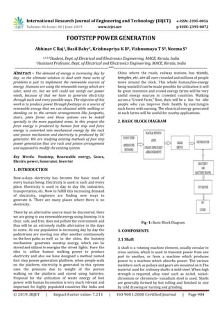
- 1. International Research Journal of Engineering and Technology (IRJET) e-ISSN: 2395-0056 Volume: 06 Issue: 06 | June 2019 www.irjet.net p-ISSN: 2395-0072 © 2019, IRJET | Impact Factor value: 7.211 | ISO 9001:2008 Certified Journal | Page 904 FOOTSTEP POWER GENERATION Abhinav C Raj1, Basil Baby2, Krishnapriya K B3, Vishnumaya T S4, Neema S5 1,2,3,4Student, Dept. of Electrical and Electronics Engineering, MACE, Kerala, India 5Assistant Professor, Dept. of Electrical and Electronics Engineering, MACE, Kerala, India ---------------------------------------------------------------------***--------------------------------------------------------------------- Abstract - The demand of energy is increasing day by day, so the ultimate solution to deal with these sorts of problems is just to implement the renewable sources of energy .Humans are using the renewable energy which are solar, wind etc. but we still could not satisfy our power needs, because of that we have to generate electricity through each and every possible ways. The objective of this work is to produce power through footsteps as a source of renewable energy that we can obtained while walking or standing on to the certain arrangements like footpaths, stairs, plate forms and these systems can be install specially in the more populated areas. In this project the force energy is produced by human foot step and force energy is converted into mechanical energy by the rack and pinion mechanism and electricity is produced by DC generator. We are studying existing methods of foot step power generation that are rack and pinion arrangement and supposed to modify the existing system. Key Words: Footstep, Renewable energy, Gears, Electric power, Generator, Inverter 1. INTRODUCTION Now-a-days electricity has become the basic need of every human being. Electricity is used in each and every place. Electricity is used in day to day life, industries, transportation, etc. Now to fulfill this increasing demand of electricity, engineers are finding new ways to generate it. There are many places where there is no electricity. There by an alternative source must be discovered. Here we are going to use renewable energy using footstep. It is clear, safe, and free, does not pollute the environment and thus will be an extremely viable alternative in the days to come. As our population is increasing day by day the pedestrians are moving one after another continuously on the foot paths as well as in the cities, the footstep mechanism generates nonstop energy, which can be stored and utilized to energize the street lights. Here the idea to utilize human walking power to produce electricity and also we have designed a method named foot step power generation platform, when people walk on the platform, electricity is generated in this system uses the pressure due to weight of the person walking on the platform and stored using batteries. Proposal for the utilization of waste energy of foot power with human locomotion is very much relevant and important for highly populated countries like India and China where the roads, railway stations, bus stands, temples, etc. are all over crowded and millions of people move around the clock. This whole human/bio-energy being wasted if can be made possible for utilization it will be great invention and crowd energy farms will be very useful energy sources in crowded countries. Walking across a ”Crowd Farm,” floor, then, will be a fun for idle people who can improve their health by exercising in such farms with earning. The electrical energy generated at such farms will be useful for nearby applications. 2. BASIC BLOCK DIAGRAM Fig -1: Basic Block Diagram 3. COMPONENTS 3.1 Shaft A shaft is a rotating machine element, usually circular in cross section, which is used to transmit power from one part to another, or from a machine which produces power to a machine which absorbs power. The various members such as pulleys and gears are mounted on it.The material used for ordinary shafts is mild steel. When high strength is required, alloy steel such as nickel, nickel- chromium or chromium- vanadium steel is used. Shafts are generally formed by hot rolling and finished to size by cold drawing or turning and grinding.
- 2. International Research Journal of Engineering and Technology (IRJET) e-ISSN: 2395-0056 Volume: 06 Issue: 06 | June 2019 www.irjet.net p-ISSN: 2395-0072 © 2019, IRJET | Impact Factor value: 7.211 | ISO 9001:2008 Certified Journal | Page 905 3.2 Bearings A bearing is a machine element that relative motion to only the desired motion, and reduces friction between moving parts. The design of the bearing may, for example, provide for free linear movement of the moving part or for free rotation around a fixed axis; or, it may prevent a motion by controlling the vectors of normal forces that bear on the moving parts. Most bearings facilitate the desired motion by minimizing friction. Fig-2: Bearing Bearings are classified broadly according to the type of operation, the motions allowed, or to the directions of the loads (forces) applied to the parts. In various equipment, there are various components moving relative to each other. Often, this relative motion involves contact between two different components. Obviously, this creates friction. The force required to impart desired motion and heat created due to the contact increases exponentially with the area of contact. The problem becomes quite critical if the parts are moving at high speed. Hence, the solution would be reducing the area of contact between moving components. It would be great if we could reducecontactarea to few points.Bearings enter the scene here.Sealed ball bearing are used to support the rotating shaft and bear its load. The inner ring fixed on shaft and the outer ring is fixed on the frame. Thus the outer ring remains stationary and inner ring helps in the smooth rotation of the shaft. 3.3 Freewheel A freewheel or overrunning clutch is a device that disengages the driveshaft from the driven shaft when the driven shaft rotates faster than the driveshaft. The condition of a driven shaft spinning faster than its driveshaft exists in most bicycles when the rider stops pedaling. In a fixed-gear bicycle, without a freewheel, the rear wheel drives the pedals around. An analogous condition exists in an automobile with a manual transmission going downhill or any situation where the driver takes their foot off the gas pedal, closing the throttle: the wheels drive the engine, possibly at a higher RPM. Fig-3: Freewheel 3.4 Gear Geared devices can change the speed, torque, and direction of a power source. Gears almost always produce a change in torque, creating a mechanical advantage, through their gear ratio, and thus may be considered a simple machine. The teeth on the two meshing gears all have the same shape. Two or more meshing gears, working in a sequence, are called a gear train or a transmission. A gear can mesh with a linear toothed part, called a rack, producing translation instead of rotation. Fig-4: Gear Wheels 3.5 DC generator Here we are using a 12V DC generator to generate electrical power. Rated speed of the motor is 1000rpm. If we could apply the force such that the rotation of motor reaches its rated speed, then the efficiency of generation will be higher. Since the generator is Permanent Magnet type, the field excitation is not necessary.
- 3. International Research Journal of Engineering and Technology (IRJET) e-ISSN: 2395-0056 Volume: 06 Issue: 06 | June 2019 www.irjet.net p-ISSN: 2395-0072 © 2019, IRJET | Impact Factor value: 7.211 | ISO 9001:2008 Certified Journal | Page 906 Fig-5: DC generator 3.6 Battery The battery used in our project for the storage purpose is Lead Acid Battery. It is the battery which uses sponge lead and lead peroxide for the conversion of the chemical energy into electrical power, such type of battery is called a lead acid battery. The lead acid battery is most commonly used in the power stations and substations becauseithashigher cell voltage and lower cost. 3.7 Inverter and Transformer 12V DC is converted into AC using the inverter circuit. This is just a driver board inverter not a boost type converter. The inverter used here is 12V 200W 50Hz square wave inverter. Fig-6: Inverter The inverted AC is further stepped up into 220V using a 12V-0-12V transformer. This stepped up energy can be used for various purposes. Power rating of the transformer is 200W. Fig-7: Transformer 4. FABRICATION DETAILS The frame structure for the total units fabricated using L- Angle frames and ordinary frames. These frames are made of mild steel. They are held to proper dimensions are attached to form a unit with the help of welding. Then the bearings which are of standard make are kept in place with their respective shafts through them and are welded to the frame structure. The shaft is made up of Galvanized iron. A rack which is made up of mild steel is welded to the upper plate arrangement. A pinion which is also made up of mild steel and which has 18 teeth is fitted on the shaft initially, and welded. This pinion tooth is exactly made to mate with the teeth of the rack. A chain arrangement is provided from the steps. The sprocket wheels are welded to the shafts. A grip pair that is made of cast iron is machined suitably to the precise dimensions in a lathe and is placed on either side of the gear wheel with its axis coinciding with the axis of the shaft and is welded. A special stand arrangement is made to seat the 12v DC generator using frames. A 12v DC generator is placed within the seat and is held firm using bolts and nuts. Wires are connected to the terminals of the DC generator and its other ends are connected to a Lead-Acid battery.
- 4. International Research Journal of Engineering and Technology (IRJET) e-ISSN: 2395-0056 Volume: 06 Issue: 06 | June 2019 www.irjet.net p-ISSN: 2395-0072 © 2019, IRJET | Impact Factor value: 7.211 | ISO 9001:2008 Certified Journal | Page 907 Fig-8: Assembly diagram of footstep generator 5. WORKING The pushing power is converted into electrical energy by proper driving arrangement. The rack pinion, spring arrangement is fixed. The function of spring is to return the step in same position by releasing the load. The shaft is connected to the supporter by end bearings. The shaft consists of free wheels (pinion) and the Shaft gear. So when a foot step is applied on the step the downward linear motion is converted into rotational motion by the rack-pinion arrangement. The free wheel only rotates when the linear motion is in the downward direction only and there is no rotation during the return action. Thus the main shaft rotates. The main shaft gear wheel is coupled to the generator shaft with the help of another gear. The gear system multiplies the generator shaft rotation according to the tooth ratio. The generator is permanent magnet D.C generator. The generated voltage is 12Volt D.C. This D.C voltage is stored to the Lead-acid 12 Volt battery. The battery is connected to the inverter. This inverter is used to convert the 12 Volt D.C to the 230 Volt A.C. This 230 Volt A.C voltage is used to activate the light, fan and etc. By increasing the capacity of battery and inverter circuit, the power rating is increased. 6. OUTPUT Fig -9 Footstep power generation output 7. CONCLUSION The system is based on the idea of electric power generation without polluting the environment. The waste energy in form of human walking is utilized in the system. It is very useful at crowded places to install this system to produce electricity. This system is smoother and less noisy in operation and provides flexibility in working. This system plays a important role for producing electricity at places where there are no sources of electricity like village areas. This energy source is renewable and continuous. As the current scenario of fastly depleting fossil fuels, on- conventional renewable power sources are vital for the world. Additionally this frame-work looks extremely Eco accommodating from the natural perspective, MLI have become more attractive for to their advantages over conventional 3-level PWM inverters. They offer improved output waveforms, smaller filter size, lower EMI, lower THD. Overall the system provides clean and cost-effective power output which can be stored or used for direct applications REFERENCES [1] TR Deshmukh. Design and analysis of a Mechanical Device to harvest energy from human footstep motion Volume 3, Special Issue 1, ICSTSD 2016. [2] Sasank shekhar Panda. An Investigation on Generation of Electricity Using Foot Step ISSN: 2277-9655 Scientific Journal Impact Factor: 3.449 (ISRA, Impact Factor: 1.852. [3] Jose Ananth Vino. Power Generation Using Foot Step, International Journal of Engineering Trends and Technology (IJETT Volume1 Issue2 May 2011. [4] Ramesh Raja R, Sherin Mathew, Power Generation from Staircase (Steps), International Journal of Innovative Research in Science, Engineering and
- 5. International Research Journal of Engineering and Technology (IRJET) e-ISSN: 2395-0056 Volume: 06 Issue: 06 | June 2019 www.irjet.net p-ISSN: 2395-0072 © 2019, IRJET | Impact Factor value: 7.211 | ISO 9001:2008 Certified Journal | Page 908 Technology, Volume 3, Special Issue 1, February 2014, ISSN : 2347 6710 [5] Alla Chandra Sekhar, B Murali Kishore ,T Jogi Raju, Electromagnetic Foot Step Power Generation, International Journal of Scientific and Research Publications, Volume 4, Issue 6, June 2014, ISSN 2250-3153 [6] Nimish Modi, Pranay Shrivastava, Rajat Bhardwaj, Umang Jaiswal, Generation Of Electricity Through Footstep, In0ternational Research Journal of Engineering and Technology (IRJET), Volume: 03 Issue: 05 — May-2016, ISSN: 2395-0072