SlideShare a Scribd company logo
1 of 8
Download to read offline
International Research Journal of Engineering and Technology (IRJET) e-ISSN: 2395-0056
Volume: 09 Issue: 08 | Aug 2022 www.irjet.net p-ISSN: 2395-0072
© 2022, IRJET | Impact Factor value: 7.529 | ISO 9001:2008 Certified Journal | Page 1313
Foundry Processes in Sand-Molded Casting of Steel
Shrutish D. Gadakh1
1 T.Y. Student, Department of Mechanical Engineering, Vishwakarma Institute of Technology, Bibwewadi, Pune
---------------------------------------------------------------------***---------------------------------------------------------------------
Abstract – Various manufacturing techniques are used by
different industries in the productionofdifferentequipmentor
spare parts of complex machinesand mechanicalassemblies. A
place where metal is molten and allowed to solidify to give ita
desired shape is called a foundry. Casting, being one of the
most ancient and convenient techniques, is used inthemaking
of complex parts of various centrifugal pumps, motors,
automobiles, etc. where the metal has to go through various
physical phases throughout the manufacturing process.
However, many supplementary steps need to be taken to
ensure a good quality of casting in order to avoid failureofthe
entire mechanical system.
Keywords – industries, machinaries, foundry, casting,
quality, failure
1. INTRODUCTION
The following paper briefly mentions the different steps
involved in the manufacturing of various steel components
such as automotive spares, engine blocks, machine tool
bases, cylinder heads, centrifugal pumps,etc.usingthesand-
casting method. Sand casting is the most widelyusedcasting
method. The advantage of using sand to manufacture metal
products is that sand is very resistant to elevated
temperatures. Almost all metal casting materialscanbesand
cast and these castings range in size from very small to
extremely large. It also explains the other necessary
measures that need to be taken to prevent failure of the
casting and enhance its strength and durability. The paper
clearly mentions the various scientific processes also called
as foundry processes in a step-by-step manner such as
pattern making, core making, molding, melting, pouring,
decoring, knockout, various cutting processes, heat
treatment cycles, shot blasting, machining, fettling,grinding,
dimensional rework, acid pickling, non-destructive testing,
finishing, punching, etc., each being equally important from
the point of view of the quality, durability and identity of the
casting. Also, the microstructure of the material, also called
as grain structure, plays an important role in defining the
properties of the entire casting. The following paper also
focuses on the various heat treatment techniques used to
obtain a definite microstructure to impart the desired
properties in the casting.
2. FLOW OF PROCESSES
Fig-1: Flow of foundry processes
3. PATTERN DESIGNING
A pattern is an exact replica of the casting which is used for
mold fabrication. Based on the volume of production and
how frequently the pattern would be used, a decision is
made upon the material to be chosen for the pattern.
Wooden patterns are usually sprayed with aluminium to
provide a better finish and prevent sand from sticking to it.
Once the pattern and the corresponding production
drawing is received from the manufacturer, the pattern is
mounted on a wooden base with the help of bolts. Then, the
locations where the different parts of the gating system
(such as risers, runners, sprue, in-gates, funnel) need to be
formed with the casting are marked. The locations where
chills are to be placed are also marked. This process is
known as Methoding. The purpose of the gating system and
chills shall be discussed in further sections of the paper.
Modifications in the pattern (if required) are done using
machining tools like lathe machine, drills, etc. Then, the
pattern is sent to the molding section. The core pattern
(called core box) does not need to be mounted on a base.
International Research Journal of Engineering and Technology (IRJET) e-ISSN: 2395-0056
Volume: 09 Issue: 08 | Aug 2022 www.irjet.net p-ISSN: 2395-0072
© 2022, IRJET | Impact Factor value: 7.529 | ISO 9001:2008 Certified Journal | Page 1314
4. CORE MAKING
It is the process of forming a solid sand core so that the
actual casting has the desired shaped cavity.
Processes involved:
A suitable composition for the sand-hardener mixture is
chosen and prepared and the bottom half of the core box is
filled with this mixture. Properly shaped metal rods are
placed in the core box for providing additional strength to
the core if required, depending on the size of the core.
Thermocol or wax strips are then placed in the sand core at
appropriate locations which melt during the oven
preheating process thus, allowingthegastoescapefromthe
core formed. This is very important to avoid crack
formation and weakening of the core. A number ofchillsare
placed in the core at appropriate locations so that they
absorb some of the heat during the solidification process of
molten metal and improve the cooling rate of the casting.
Then the top half of the core box is placed and clamped to
the bottom half to prevent core expansion during
preheating. The sand mixture is also added in the tophalfto
complete the core. Risers are placed wherever required in
the core. Several voids are also created in the core to allow
air to escape during preheating. Removal of excess sand
takes place and the core is left undisturbed for a specified
time to harden. The hardening time depends upon the type
of hardener used. The core is sent for dressing and painting
where it is spray painted with an inflammable mixture of
paint and thinner which is set on fire so that the moisturein
the core gets removed. The core is then placed in the
preheating oven for 5-6 hours for further hardening and
moisture removal. Then the core is sent to the core setting
section where it is placed between the two halves of the
mold before sending it to the pouring section. This is done
by placing the core in the drag (bottom halfofthemold)and
then placing and gluing the cope (top half of the mold) over
it.
5. MOLDING
It is the process of forming a mold of the desired shape that
is further filled with molten metal to form the desired
shaped casting.
Processes involved:
The mold is first divided into two halves viz. cope (top half)
and drag (bottom half) and the two halves are formed
separately. The mold pattern is placed into the mold box
and accessories like the funnel,sleeves,L-blends,fire bricks,
etc. are placed at appropriate locations for forming the
gating system along with the casting. The sand-hardener-
resin mixture is prepared withsuitablecompositionandthe
mold box is filled with this sand mixture. The sand is then
pressed tightly in the mold box and then allowed to solidify.
The above processes can be done manually or with the help
of machinaries depending upon the size of the mold. The
hardened mold is then spray painted with paintandthinner
mixture which is set on fire toremovethemoisturefromthe
mold. Both the mold halves are passed through the
preheating oven for further hardening and moisture
removal. Then the corresponding core is placed in the drag
and the cope is then inverted and placed over the drag and
glued to it to form the complete mold which is then taken to
the pouring section.
Fig-2: Arrangement of complete mold
6. MELTING
Scrap collected from various sources is first segregated as
per the material grade. The scrap is first heated in an oven
before sending it to the furnace so that it melts quicker. The
furnace used is an induction furnace where a number of
copper coils are present around the furnace and carry a
huge current that creates an electric field and induces a
current (Eddy current) in the scrap. This results in heating
of the scrap and melts it. These furnaces are lined inside
with refractory material to prevent melting of the furnace
walls. Temperature of the furnace is maintained above the
melting point of the material grade and the temperature of
the molten metal is checked frequently using a
thermocouple. Supply of Argon gas is provided through
pipes at the bottom of the furnace. This gas, being inert,
does not react with the metal but liftstheimpuritiespresent
in it. These impurities are adsorbed by the slack powder
sprinkled over the furnace. Specific amounts of Aluminium
(ingot and shots) and Calcium Silicide are added to the
molten metal for deoxidation of steel.Otherwise,reaction of
the metal with oxygen may alter its properties.
7. POURING
The molten metal is poured into certain ladles thatarelined
inside with refractory material. The lining is done to
prevent the ladles from melting as the temperature of the
International Research Journal of Engineering and Technology (IRJET) e-ISSN: 2395-0056
Volume: 09 Issue: 08 | Aug 2022 www.irjet.net p-ISSN: 2395-0072
© 2022, IRJET | Impact Factor value: 7.529 | ISO 9001:2008 Certified Journal | Page 1315
molten metal is very high. Also, the ladle is first heated to a
certain temperature before pouring molten metal into it to
reduce the cooling rate of the metal. Otherwise, the molten
metal may solidify even before reaching the entire mould
thus, resulting in undesirable casting. Ladles are of two
types viz., lip pouring and bottom pouring and have a
steering to control the orientation of the ladle. Lip pouring
ladles need to be tilted to pour the metal whereas bottom
pouring ladles have an opening at the base that can the
opened or closed by lifting or releasing a heavy rod called
bottom pouring rod. Slack powder is then sprinkled on top
of the ladle to remove impurities. The lid of the ladle is
covered with an insulating material like glass wool to
prevent heat losses to the surrounding.Moltenmetal isthen
poured in the pouring basin and is further carried to the
entire mold by the gating system (sprue, runners, in-gates,
risers). Also, the gas in the mold is allowed to burn to
prevent it from getting trapped in the mold. A riser (feeder)
is used to prevent cavities in the casting that can form due
to shrinkage of the metal on solidification. This is done by
providing excess metal to the mold so that the cavity forms
in the riser and not the casting. Anti-piping Compound
(APC) powder is then added on top of the riser opening.
This has the following advantages. Firstly, it prevents the
sparks of the molten metal from reaching the workmen.
Also, the metal in the riser is exposed to atmosphere
because of which the cooling and solidification may start
from the riser itself which is undesirable. Addition of APC
breaks this exposure and the use of sleeves (made of
exothermic material) keeps the metal intherisermoltenfor
a longer duration than the casting. The casting cools at a
comparatively faster rate due to the presence of chills. A
small amount of metal is poured in a sample/test mold that
is further used for inspecting the quality and properties of
the casting
8. DECORING AND KNOCKOUT
Both the test sample and the casting are allowed to solidify
and then taken to the casting decoring area where the mold
is broken down and the casting is removed. The pieces of
sand mold are sent to the knockdown section by a
motorized trolley where heavy vibrations of the container
result in breakdown of the mold pieces to fine sand. This
sand, being a mixture of various sands, is sent for
purification and reuse. The casting can also be removed in
the knockout section itself. The casting is then allowed to
cool using air quenching or water quenching.
9. GAS CUTTING, POWDER CUTTING AND ROD
GOUGING
After the casting is cooled by quenching, it is taken to the
cutting and gouging section to remove the unwanted parts
that are not required in the casting i.e., funnel, risers,
runners, gates, sprue, etc.
Gas cutting: Mixture of oxygen and Acetylene is used to
preheat the metal to its ignition temperature(for steel,700-
900 degree Celsius) but below its melting point. A jet of
oxygen is directed into the preheated area initiating a
vigorous exothermic chemical reaction between the metal
and oxygen to form a metal oxide or slag. The oxygen jet
blows away the slag enabling the jet to pierce through the
material and continue to cut through it. Ignition
temperature of the material must be lower than its melting
point otherwise, the material would melt and flow away
before cutting. Oxide melting point should be lower than
that of the surrounding material so that it can be
mechanically blown away by the oxygen jet. Oxidation
reaction between the oxygen jet and metal must be
sufficient to maintain the ignition temperature. Minimum
gaseous reaction products should be formed so as not to
dilute the cutting oxygen.
Powder cutting: It is similar to gas cutting with an addition
of iron powder to the oxygen jet. Stainless steel, cast iron,
nonferrous metals form refractory oxides (Oxides whose
melting point is higher than the material). Hence, powder is
injected into the flame to form a fluid slag with low melting
point. Acetylene, propane, MAPP (Methylacetylene-
propadiene), propylene, natural gas arethecommonlyused
fuel gases among which acetylene produces the highest
flame temperature.
Fig-3: Gas cutting
International Research Journal of Engineering and Technology (IRJET) e-ISSN: 2395-0056
Volume: 09 Issue: 08 | Aug 2022 www.irjet.net p-ISSN: 2395-0072
© 2022, IRJET | Impact Factor value: 7.529 | ISO 9001:2008 Certified Journal | Page 1316
Fig-4: Powder cutting
Rod gouging (Air carbon arc gouging): It is the process of
removing material by means of heat generated by carbon
arc. It removes excess material from casting and requires a
carbon/graphite electrode,compressedair,standardpower
source (like welding rectifier). An intense electric arc
produced between tip of rod and workpiece cuts and melts
the workpiece. Compressed air is usedfor blowingawaythe
molten metal thoroughly from the casting surface. The
metal is gouged (cut) in the airflow direction. It is used to
remove excess weld beads also. The power source must
have a constant current output characteristic otherwise,the
high voltage current can cause the electrode tip to explode
when touched to the workpiece. Copper coating is given to
the graphite rod to reduce electrode erosion. Sometimes,
water is poured simultaneously on the surrounding area to
prevent it from cracking due to excess heat.
10. HEAT TREATMENT
Process of heating the casting below its melting point to
relieve internal stresses developed by forging, welding or
during solidification itself. It is used to increase/decrease
hardness of the material by achieving the desired grain
structure.
Processes involved:
The heat treatment furnaces are first lined with insulating
material (glass wool) on the inside to prevent heat losses.
Heat treatment process is controlled by heat treatment
furnace control panel. The furnacetemperatureisincreased
to a specific set point in multiple cycles. This process is
called as Ramping. The starting time of the process isnoted.
Once the temperature of the furnaces reaches the desired
maximum, it is held for a specific time. This processiscalled
as Soaking. The cooling methodtobeusedispredefined.For
air quenching, the number of running fans is already
specified. Multiple burners are provided inside the furnace
to maintain a uniform temperature throughout the casting.
The temperature at different locations within the casting
are measured using thermocouples.
Fig-5: Basic types of heat treatment
10.1 Normalizing
It involves heating the casting above recrystallization
temperature (727 degrees for steel), then soaking for a
specific time till the desired microstructure has been
achieved and then cooling by air quenching.
10.2 Annealing
This process involves heating the casting above
recrystallization temperature(727degrees),soakingforthe
specified time and then cooling by controlled furnace
cooling.
Air quenching cools at a faster rate than controlled furnace
cooling. Faster the rate of cooling, finer is the grain
structure hence, greater isthehardness.Normalizedcasting
is harder as compared to annealed casting. Therefore, it is
brittle and difficult to machine. Normalizing temperatures
are usually higher than annealing temperatures.
Both normalizing and annealing take place in 3 stages viz.
recovery stage, recrystallization stage and grain-growth
stage.
Recovery stage: In this stage, the furnace or other heating
device is used to raise the temperature of the material so
that the internal stresses are relieved.
Recrystallization stage: It involves heating the material
above its recrystallization temperaturebut belowitsmelting
point so that new grains are formed without any residual
stresses.
Grain-growth stage: The material is cooled at a specific rate
causing new grains to develop after which the material will
be more workable. After annealing and normalizing,various
subsequent operationscanbecarriedouttoaltermechanical
properties.
International Research Journal of Engineering and Technology (IRJET) e-ISSN: 2395-0056
Volume: 09 Issue: 08 | Aug 2022 www.irjet.net p-ISSN: 2395-0072
© 2022, IRJET | Impact Factor value: 7.529 | ISO 9001:2008 Certified Journal | Page 1317
10.3 Hardening
This process is done by heating the casting above
recrystallization temperature (727 degrees), then soaking
for a specific time and then cooling by dipping in water.
Water cools the casting immediately and this results in a
very fine grain structure. Hence, the casting becomes very
hard and brittle and thus, difficult to machine.
Water, brine, oil, etc. are used for solution treatment or
solution quenching.
10.4 Tempering
Normalized or water quenched (solution treated) castings
are usually very hard. Hence, to reduce hardness and
increase machinability, tempering is done.
Here, casting is heated below recrystallizationtemperature,
soaked for a specific time and then cooled at a specific rate
to get the desired properties like hardness, grain structure,
machinability, etc. (either by controlled furnace cooling or
air quenching). After the heat treatment, the casting is sent
for shot blasting and further processes.
In the above processes, the casting is not heated to the final
temperature in one step but rather in multiple steps by
holding the casting at several intermediate temperatures.
Fig-6: Ramping and soaking
11. SHOT BLASTING
The undesirable black rusty layer developed on the casting
after heat treatment gets removed by shot blasting. Very
fine shots (made of aluminium, steel, etc.) are blasted with
high velocity upon the casting with the help of multiple
motors and corresponding impellers.The machine worksin
a cyclic manner i.e., the shots falling down are collected and
reused. The castings are taken to and removed from the
machine with the help of hangers provided around the
machine. The castings are kept in the shot blasting machine
for 5-6 minutes. After the process, the casting becomes
clean and greyish in colour. Also, any sand present in the
casting gets removed and the voids on the surface get
opened After this, the casting is sent for primaryinspection.
If the defects are workable, only then the casting is sent for
further processing or else it is rejected.
12. MACHINING/FETTLING/GRINDING
The excess material remained on the casting after powder
cutting and rod gougingisremoved bymachiningorfettling.
The casting is machinedtodesireddimensionswiththehelp
of various machining tools. The feet and flanges of the
involute casing are machined to desired dimensions and
finish. This is usually done for the castings that are to be
exported. The casting is given a smooth, shinysurfacefinish
by grinding operations.
Then, the dimensions of the casting obtained are compared
with the expected dimensions. Any dimension greater than
the desired one is reduced by rod gouging and dimensions
smaller than the desired ones are increased by welding.
Then, the affected area is again given a smooth finish by
grinding.
13. ACID PICKLING
It is a surface treatment used to remove impurities such as
stains, inorganic contaminants, rust or scale (oxide layer
formed during hot working processes), etc. These are
removed by reactions with mineral acids. As the damaged
metal layer gets removed, a properly alloyed steel surface
gets exposed providing a good corrosion resistant
performance. Commonly used acids for pickling are
sulphuric acid, hydrochloric acid, nitric acid, hydrofluoric
acid, phosphoric acid. Hydrochloric acid is used in steel
castings. Even though it is more expensive than sulphuric
acid, it pickles at a faster rate while minimizing base metal
loss.
14. NON-DESTRUCTIVE TESTING (NDT)
Here, the casting goes through a number of quality tests
without actually damaging or wasting the casting unlike
tensile test, Brienell hardness test, etc.
International Research Journal of Engineering and Technology (IRJET) e-ISSN: 2395-0056
Volume: 09 Issue: 08 | Aug 2022 www.irjet.net p-ISSN: 2395-0072
© 2022, IRJET | Impact Factor value: 7.529 | ISO 9001:2008 Certified Journal | Page 1318
Fig-7: Types of NDT
14.1 Liquid Penetrant Test
The casting is first cleaned with red fluorescent paint. The
paint is then allowed to settle and enter the surface pores
and cracks for about 15 minutes. Then the entire casting is
washed using water and solvent based cleaner and dried
using air blower. A developer solution is sprayed on the
casting which turns the entire casting white after sometime
and exposes the fluorescent paint at locations where there
are defects. Based on the severity ofthedefects,a decisionis
made upon which defects to ignore and which ones to fix.
Then the entire casting is washed and the defective
locations are marked. The paint penetrated in the cracks
and holes is removed by a water washable penetrant.
14.2 Magnetic Particle Test
It is used for detection of surface and near-surface flaws in
ferromagnetic materials and is primarily used for crack
detection. The workpiece is magnetized and the magnetic
flux is present predominantly inside the material. If there is
any surface breaking flaw, the magnetic field is distorted,
causing local magnetic flux leakage around the flaw. This
leakage flux is displayed by covering the surface with very
fine iron particles suspended in diesel. The particles
accumulate at the regions of flux leakage,producinga build-
up which can be seen visually even if the crack is very small
and narrow. Thus, a crack is indicated as a visible line of
iron powder or magnetic particles on the surface.
Fig-8: Magnetic particle testing
Magnetization can be produced by any of the following
ways:
By applying a permanent/electromagnet to the surface
which is termed as magnetic flow
By passing a large current through the overall specimen or
it can be done locally by means of current prods
By putting the component/specimen inside a current
carrying loop
By threading a current carrying bar through a hollow
specimen
The method of magnetization should produce a magnetic
field such that the lines of force are at large angles to the
expected direction of cracks to be detected. So,
magnetization is done more than once in different
directions. This can also be done using a combinationoftwo
magnetic fields so that a swinging or rotating magneticfield
can be produced which will detect a crack in any
direction/orientation
14.3 Radiographic Testing
Ionizing radiations are usedtopenetratethecross-sectional
area of a casting and a piece of radiographic film is exposed.
When discontinuities like cracks, gas, shrinkage or unfused
chills or chaplets are present in a casting, the casting
absorbs less radiation and more radiation reaches the film.
This increased film exposure of the radiation ultimately
produces an image of the discontinuityonthefilm.X-raysor
Gamma rays are used to pass ionizing radiations through
the casting.
International Research Journal of Engineering and Technology (IRJET) e-ISSN: 2395-0056
Volume: 09 Issue: 08 | Aug 2022 www.irjet.net p-ISSN: 2395-0072
© 2022, IRJET | Impact Factor value: 7.529 | ISO 9001:2008 Certified Journal | Page 1319
Fig-9: Radiographic testing
14.4 Ultrasonic Testing
This method uses high frequency sound waves to detect
surface and subsurface discontinuities in castings. It can
also measure the thickness of the casting at locationswhere
the human hand or mechanical devices cannot reach. Here,
an ultrasonic transducer transforms electrical energy into
mechanical energy in the form of soundpressurewavesand
the sound pulse thus, generated initiates at the transducer,
travels through the casting and is reflected by boththe back
wall of the casting and any discontinuities that may be
present. The transducer senses the reflected sound wave
and converts it to an electrical signal. The properties of the
sound wave like transit time, amplitude and shape give an
idea about any defects present.
Fig-10: Ultrasonic testing
Once the defective locations are marked, they are entirely
removed by rod gouging and then welded. The excess of
weld bead is removed by grinding and then the casting is
sent for post weld heat treatment to relieve the stresses
developed in the weld. After the post weld heat treatment
(PWHT), the casting is again sent for shot blasting (for
carbon steels) or grit blasting (for stainless steels). The
material used for grit blasting is aluminium. The NDTs are
performed again to ensure whether the defects have been
fixed or not. Final finishing and acid pickling is done once
again after all the defects have been removed.
15. Punching
Large castings usually have heat numbers, pattern numbers
and material grades embossed/extrudedonthemalong with
the casting itself. However, some small castings need to be
punched using metal stamping technique. The stamp has a
specific dimension and has a letter or number
embossed/extruded at its tip. The stamp of the correct size
and letter must be chosen for punching. Holding the stamp
vertically and hammering it 2-3 times creates a punch of the
desired letter or number on the casting After all the above
processes, the casting is finally ready for dispatch.
16. CONCLUSIONS
This paper explains most of the processes involved in sand
casting of steels. It takes into account not only the basic
foundry processes of molding,scrapmeltingandpouring but
also the additional steps taken to ensure a good quality of
the overall casting. The properties of the casting highly
depend on the quality of the mold and hence, a number of
steps are taken to strengthen themoldandremoveanyvoids
or moisture contained within it. Moreover, the process of
scrap melting needs to be done carefully wherein additional
alloying elements need to be added to obtain the desired
composition of the material.
This study also explains the basics of heat treatment of steel
castings. However, more research needs to be done in order
to obtain detailed information about the various physical
phases and the corresponding microstructures of steel
obtained during heat treatment. A number of
transformations take place during heat treatment
(martensite, austenite, bainite, pearlite, etc.) resulting in
different mechanical properties of the component.
A number of machining and finishing processes have been
mentioned in the paper. However, the importance of each of
them highly depends on the type of the component and the
desired finish. Also, the availability of resources can affect
the application of any process in a foundry. Many
organizations, due to unavailability of space and resources,
have to outsource in order to complete a given process.Also,
the materials, tools and equipment used for different
processes vary from company to company leading to
International Research Journal of Engineering and Technology (IRJET) e-ISSN: 2395-0056
Volume: 09 Issue: 08 | Aug 2022 www.irjet.net p-ISSN: 2395-0072
© 2022, IRJET | Impact Factor value: 7.529 | ISO 9001:2008 Certified Journal | Page 1320
different quality of finished products. Moreover, the quality
and volume of production also depend upon the extent to
which manual labour and automation are implemented.
REFERENCES
[1] Design and Manufacture of Casting Pattern Plates by
Rapid Tooling, A. Pereira, J. A. Pérez, J. L. Diéguez, G.Peláez,J.
E. Are
[2] Gating and Risering in Vertical Green Sand Moulds, N. W.
Rasmussen, R. Aagaard and P. N. Hansen
[3] A Study of Core and it’s types forCastingProcess,Dhairya
S. Deore, Gunjan B. Chaudhari, Aman G. Chaturvedi,Shrikant
Uttam Gunjal
[4] Optimal feeder design in sand casting process by growth
method, R. Tavakoli and P. Davami
[5] Foundry quality control aspects and prospects to reduce
scrap rework and rejection in metal casting manufacturing
industries, T.R. Vijayaram, S. Sulaiman, A.M.S. Hamouda,
M.H.M. Ahmad
[6] Comparative Study of Air Carbon Arc GougingProcess on
Sae 316 Stainless Steel, Anoop G Das, R. Abarna
[7] Kinetics of Oxyfuel Gas Cutting of Steels, Adedayo,
Adeleke Victor
[8] Evaluation of Material Quality for Liquid-Penetrant
Inspection Based on the Visibility oftheIndicatorPatternsof
Flaws, Yu. A. Glazkov
[9] Reliability and sensitivity of magnetic particle non-
destructive testing in detecting the surface cracks of welded
components

More Related Content

Similar to Foundry Processes in Sand-Molded Casting of Steel

Final Project Report- Shreyas Gupta, IIT Guwahati
Final Project Report- Shreyas Gupta, IIT GuwahatiFinal Project Report- Shreyas Gupta, IIT Guwahati
Final Project Report- Shreyas Gupta, IIT GuwahatiShreyas Gupta
 
Warpage in casting a review
Warpage in casting a reviewWarpage in casting a review
Warpage in casting a reviewLaukik Raut
 
advanced casting.pdf
advanced casting.pdfadvanced casting.pdf
advanced casting.pdfssuser9cb807
 
Advanced casting and welding
Advanced casting and weldingAdvanced casting and welding
Advanced casting and weldingK GOLD KING
 
IRJET- Fabrication of Foundry Cum Forging Furnace
IRJET- Fabrication of Foundry Cum Forging FurnaceIRJET- Fabrication of Foundry Cum Forging Furnace
IRJET- Fabrication of Foundry Cum Forging FurnaceIRJET Journal
 
1435936220 volume 2 issue 5 (may 2015)
1435936220 volume 2 issue 5 (may  2015)1435936220 volume 2 issue 5 (may  2015)
1435936220 volume 2 issue 5 (may 2015)ijiert bestjournal
 
Presentation study of manufacturing process in hmt machine tools limited.docx
Presentation study of manufacturing process in hmt machine tools limited.docxPresentation study of manufacturing process in hmt machine tools limited.docx
Presentation study of manufacturing process in hmt machine tools limited.docxAbu Sufyan Malik
 
ME 6302 manufacturing technology 1notes with question paper
ME 6302 manufacturing technology 1notes with question paperME 6302 manufacturing technology 1notes with question paper
ME 6302 manufacturing technology 1notes with question paperGopinath Guru
 
Productivity improvement of castings, switching to shell mould process from g...
Productivity improvement of castings, switching to shell mould process from g...Productivity improvement of castings, switching to shell mould process from g...
Productivity improvement of castings, switching to shell mould process from g...eSAT Publishing House
 
Manufacturing of liquid propellant tank
Manufacturing of liquid propellant tankManufacturing of liquid propellant tank
Manufacturing of liquid propellant tankSai Malleswar
 
STUDY OF PROCESS PARAMETERS OF GRAVITY DIE CASTING DEFECTS
STUDY OF PROCESS PARAMETERS OF GRAVITY DIE CASTING DEFECTSSTUDY OF PROCESS PARAMETERS OF GRAVITY DIE CASTING DEFECTS
STUDY OF PROCESS PARAMETERS OF GRAVITY DIE CASTING DEFECTSIAEME Publication
 
Die casting process: Principles, applications and industrial use
Die casting process: Principles, applications and industrial useDie casting process: Principles, applications and industrial use
Die casting process: Principles, applications and industrial useMayurjyotiNeog
 

Similar to Foundry Processes in Sand-Molded Casting of Steel (20)

Final Project Report- Shreyas Gupta, IIT Guwahati
Final Project Report- Shreyas Gupta, IIT GuwahatiFinal Project Report- Shreyas Gupta, IIT Guwahati
Final Project Report- Shreyas Gupta, IIT Guwahati
 
Shell moulding
Shell moulding Shell moulding
Shell moulding
 
Warpage in casting a review
Warpage in casting a reviewWarpage in casting a review
Warpage in casting a review
 
U3 p3 special casting methods
U3 p3 special casting methodsU3 p3 special casting methods
U3 p3 special casting methods
 
ME6302 MANUFACTURING TECHNOLOGY – I BY Mr.K.SIVAKUMAR /AP/MECH/KIT/CBE
ME6302 MANUFACTURING TECHNOLOGY – I BY Mr.K.SIVAKUMAR /AP/MECH/KIT/CBEME6302 MANUFACTURING TECHNOLOGY – I BY Mr.K.SIVAKUMAR /AP/MECH/KIT/CBE
ME6302 MANUFACTURING TECHNOLOGY – I BY Mr.K.SIVAKUMAR /AP/MECH/KIT/CBE
 
advanced casting.pdf
advanced casting.pdfadvanced casting.pdf
advanced casting.pdf
 
Advanced casting and welding
Advanced casting and weldingAdvanced casting and welding
Advanced casting and welding
 
IRJET- Fabrication of Foundry Cum Forging Furnace
IRJET- Fabrication of Foundry Cum Forging FurnaceIRJET- Fabrication of Foundry Cum Forging Furnace
IRJET- Fabrication of Foundry Cum Forging Furnace
 
Ch 22 special casting
Ch 22 special castingCh 22 special casting
Ch 22 special casting
 
Expendable mould processes
Expendable mould processesExpendable mould processes
Expendable mould processes
 
1435936220 volume 2 issue 5 (may 2015)
1435936220 volume 2 issue 5 (may  2015)1435936220 volume 2 issue 5 (may  2015)
1435936220 volume 2 issue 5 (may 2015)
 
Presentation study of manufacturing process in hmt machine tools limited.docx
Presentation study of manufacturing process in hmt machine tools limited.docxPresentation study of manufacturing process in hmt machine tools limited.docx
Presentation study of manufacturing process in hmt machine tools limited.docx
 
ME 6302 manufacturing technology 1notes with question paper
ME 6302 manufacturing technology 1notes with question paperME 6302 manufacturing technology 1notes with question paper
ME 6302 manufacturing technology 1notes with question paper
 
2 casting
2 casting2 casting
2 casting
 
Shruthi paper
Shruthi paperShruthi paper
Shruthi paper
 
Productivity improvement of castings, switching to shell mould process from g...
Productivity improvement of castings, switching to shell mould process from g...Productivity improvement of castings, switching to shell mould process from g...
Productivity improvement of castings, switching to shell mould process from g...
 
Manufacturing of liquid propellant tank
Manufacturing of liquid propellant tankManufacturing of liquid propellant tank
Manufacturing of liquid propellant tank
 
STUDY OF PROCESS PARAMETERS OF GRAVITY DIE CASTING DEFECTS
STUDY OF PROCESS PARAMETERS OF GRAVITY DIE CASTING DEFECTSSTUDY OF PROCESS PARAMETERS OF GRAVITY DIE CASTING DEFECTS
STUDY OF PROCESS PARAMETERS OF GRAVITY DIE CASTING DEFECTS
 
Shell and Investment Casting.pdf
Shell and Investment Casting.pdfShell and Investment Casting.pdf
Shell and Investment Casting.pdf
 
Die casting process: Principles, applications and industrial use
Die casting process: Principles, applications and industrial useDie casting process: Principles, applications and industrial use
Die casting process: Principles, applications and industrial use
 

More from IRJET Journal

TUNNELING IN HIMALAYAS WITH NATM METHOD: A SPECIAL REFERENCES TO SUNGAL TUNNE...
TUNNELING IN HIMALAYAS WITH NATM METHOD: A SPECIAL REFERENCES TO SUNGAL TUNNE...TUNNELING IN HIMALAYAS WITH NATM METHOD: A SPECIAL REFERENCES TO SUNGAL TUNNE...
TUNNELING IN HIMALAYAS WITH NATM METHOD: A SPECIAL REFERENCES TO SUNGAL TUNNE...IRJET Journal
 
STUDY THE EFFECT OF RESPONSE REDUCTION FACTOR ON RC FRAMED STRUCTURE
STUDY THE EFFECT OF RESPONSE REDUCTION FACTOR ON RC FRAMED STRUCTURESTUDY THE EFFECT OF RESPONSE REDUCTION FACTOR ON RC FRAMED STRUCTURE
STUDY THE EFFECT OF RESPONSE REDUCTION FACTOR ON RC FRAMED STRUCTUREIRJET Journal
 
A COMPARATIVE ANALYSIS OF RCC ELEMENT OF SLAB WITH STARK STEEL (HYSD STEEL) A...
A COMPARATIVE ANALYSIS OF RCC ELEMENT OF SLAB WITH STARK STEEL (HYSD STEEL) A...A COMPARATIVE ANALYSIS OF RCC ELEMENT OF SLAB WITH STARK STEEL (HYSD STEEL) A...
A COMPARATIVE ANALYSIS OF RCC ELEMENT OF SLAB WITH STARK STEEL (HYSD STEEL) A...IRJET Journal
 
Effect of Camber and Angles of Attack on Airfoil Characteristics
Effect of Camber and Angles of Attack on Airfoil CharacteristicsEffect of Camber and Angles of Attack on Airfoil Characteristics
Effect of Camber and Angles of Attack on Airfoil CharacteristicsIRJET Journal
 
A Review on the Progress and Challenges of Aluminum-Based Metal Matrix Compos...
A Review on the Progress and Challenges of Aluminum-Based Metal Matrix Compos...A Review on the Progress and Challenges of Aluminum-Based Metal Matrix Compos...
A Review on the Progress and Challenges of Aluminum-Based Metal Matrix Compos...IRJET Journal
 
Dynamic Urban Transit Optimization: A Graph Neural Network Approach for Real-...
Dynamic Urban Transit Optimization: A Graph Neural Network Approach for Real-...Dynamic Urban Transit Optimization: A Graph Neural Network Approach for Real-...
Dynamic Urban Transit Optimization: A Graph Neural Network Approach for Real-...IRJET Journal
 
Structural Analysis and Design of Multi-Storey Symmetric and Asymmetric Shape...
Structural Analysis and Design of Multi-Storey Symmetric and Asymmetric Shape...Structural Analysis and Design of Multi-Storey Symmetric and Asymmetric Shape...
Structural Analysis and Design of Multi-Storey Symmetric and Asymmetric Shape...IRJET Journal
 
A Review of “Seismic Response of RC Structures Having Plan and Vertical Irreg...
A Review of “Seismic Response of RC Structures Having Plan and Vertical Irreg...A Review of “Seismic Response of RC Structures Having Plan and Vertical Irreg...
A Review of “Seismic Response of RC Structures Having Plan and Vertical Irreg...IRJET Journal
 
A REVIEW ON MACHINE LEARNING IN ADAS
A REVIEW ON MACHINE LEARNING IN ADASA REVIEW ON MACHINE LEARNING IN ADAS
A REVIEW ON MACHINE LEARNING IN ADASIRJET Journal
 
Long Term Trend Analysis of Precipitation and Temperature for Asosa district,...
Long Term Trend Analysis of Precipitation and Temperature for Asosa district,...Long Term Trend Analysis of Precipitation and Temperature for Asosa district,...
Long Term Trend Analysis of Precipitation and Temperature for Asosa district,...IRJET Journal
 
P.E.B. Framed Structure Design and Analysis Using STAAD Pro
P.E.B. Framed Structure Design and Analysis Using STAAD ProP.E.B. Framed Structure Design and Analysis Using STAAD Pro
P.E.B. Framed Structure Design and Analysis Using STAAD ProIRJET Journal
 
A Review on Innovative Fiber Integration for Enhanced Reinforcement of Concre...
A Review on Innovative Fiber Integration for Enhanced Reinforcement of Concre...A Review on Innovative Fiber Integration for Enhanced Reinforcement of Concre...
A Review on Innovative Fiber Integration for Enhanced Reinforcement of Concre...IRJET Journal
 
Survey Paper on Cloud-Based Secured Healthcare System
Survey Paper on Cloud-Based Secured Healthcare SystemSurvey Paper on Cloud-Based Secured Healthcare System
Survey Paper on Cloud-Based Secured Healthcare SystemIRJET Journal
 
Review on studies and research on widening of existing concrete bridges
Review on studies and research on widening of existing concrete bridgesReview on studies and research on widening of existing concrete bridges
Review on studies and research on widening of existing concrete bridgesIRJET Journal
 
React based fullstack edtech web application
React based fullstack edtech web applicationReact based fullstack edtech web application
React based fullstack edtech web applicationIRJET Journal
 
A Comprehensive Review of Integrating IoT and Blockchain Technologies in the ...
A Comprehensive Review of Integrating IoT and Blockchain Technologies in the ...A Comprehensive Review of Integrating IoT and Blockchain Technologies in the ...
A Comprehensive Review of Integrating IoT and Blockchain Technologies in the ...IRJET Journal
 
A REVIEW ON THE PERFORMANCE OF COCONUT FIBRE REINFORCED CONCRETE.
A REVIEW ON THE PERFORMANCE OF COCONUT FIBRE REINFORCED CONCRETE.A REVIEW ON THE PERFORMANCE OF COCONUT FIBRE REINFORCED CONCRETE.
A REVIEW ON THE PERFORMANCE OF COCONUT FIBRE REINFORCED CONCRETE.IRJET Journal
 
Optimizing Business Management Process Workflows: The Dynamic Influence of Mi...
Optimizing Business Management Process Workflows: The Dynamic Influence of Mi...Optimizing Business Management Process Workflows: The Dynamic Influence of Mi...
Optimizing Business Management Process Workflows: The Dynamic Influence of Mi...IRJET Journal
 
Multistoried and Multi Bay Steel Building Frame by using Seismic Design
Multistoried and Multi Bay Steel Building Frame by using Seismic DesignMultistoried and Multi Bay Steel Building Frame by using Seismic Design
Multistoried and Multi Bay Steel Building Frame by using Seismic DesignIRJET Journal
 
Cost Optimization of Construction Using Plastic Waste as a Sustainable Constr...
Cost Optimization of Construction Using Plastic Waste as a Sustainable Constr...Cost Optimization of Construction Using Plastic Waste as a Sustainable Constr...
Cost Optimization of Construction Using Plastic Waste as a Sustainable Constr...IRJET Journal
 

More from IRJET Journal (20)

TUNNELING IN HIMALAYAS WITH NATM METHOD: A SPECIAL REFERENCES TO SUNGAL TUNNE...
TUNNELING IN HIMALAYAS WITH NATM METHOD: A SPECIAL REFERENCES TO SUNGAL TUNNE...TUNNELING IN HIMALAYAS WITH NATM METHOD: A SPECIAL REFERENCES TO SUNGAL TUNNE...
TUNNELING IN HIMALAYAS WITH NATM METHOD: A SPECIAL REFERENCES TO SUNGAL TUNNE...
 
STUDY THE EFFECT OF RESPONSE REDUCTION FACTOR ON RC FRAMED STRUCTURE
STUDY THE EFFECT OF RESPONSE REDUCTION FACTOR ON RC FRAMED STRUCTURESTUDY THE EFFECT OF RESPONSE REDUCTION FACTOR ON RC FRAMED STRUCTURE
STUDY THE EFFECT OF RESPONSE REDUCTION FACTOR ON RC FRAMED STRUCTURE
 
A COMPARATIVE ANALYSIS OF RCC ELEMENT OF SLAB WITH STARK STEEL (HYSD STEEL) A...
A COMPARATIVE ANALYSIS OF RCC ELEMENT OF SLAB WITH STARK STEEL (HYSD STEEL) A...A COMPARATIVE ANALYSIS OF RCC ELEMENT OF SLAB WITH STARK STEEL (HYSD STEEL) A...
A COMPARATIVE ANALYSIS OF RCC ELEMENT OF SLAB WITH STARK STEEL (HYSD STEEL) A...
 
Effect of Camber and Angles of Attack on Airfoil Characteristics
Effect of Camber and Angles of Attack on Airfoil CharacteristicsEffect of Camber and Angles of Attack on Airfoil Characteristics
Effect of Camber and Angles of Attack on Airfoil Characteristics
 
A Review on the Progress and Challenges of Aluminum-Based Metal Matrix Compos...
A Review on the Progress and Challenges of Aluminum-Based Metal Matrix Compos...A Review on the Progress and Challenges of Aluminum-Based Metal Matrix Compos...
A Review on the Progress and Challenges of Aluminum-Based Metal Matrix Compos...
 
Dynamic Urban Transit Optimization: A Graph Neural Network Approach for Real-...
Dynamic Urban Transit Optimization: A Graph Neural Network Approach for Real-...Dynamic Urban Transit Optimization: A Graph Neural Network Approach for Real-...
Dynamic Urban Transit Optimization: A Graph Neural Network Approach for Real-...
 
Structural Analysis and Design of Multi-Storey Symmetric and Asymmetric Shape...
Structural Analysis and Design of Multi-Storey Symmetric and Asymmetric Shape...Structural Analysis and Design of Multi-Storey Symmetric and Asymmetric Shape...
Structural Analysis and Design of Multi-Storey Symmetric and Asymmetric Shape...
 
A Review of “Seismic Response of RC Structures Having Plan and Vertical Irreg...
A Review of “Seismic Response of RC Structures Having Plan and Vertical Irreg...A Review of “Seismic Response of RC Structures Having Plan and Vertical Irreg...
A Review of “Seismic Response of RC Structures Having Plan and Vertical Irreg...
 
A REVIEW ON MACHINE LEARNING IN ADAS
A REVIEW ON MACHINE LEARNING IN ADASA REVIEW ON MACHINE LEARNING IN ADAS
A REVIEW ON MACHINE LEARNING IN ADAS
 
Long Term Trend Analysis of Precipitation and Temperature for Asosa district,...
Long Term Trend Analysis of Precipitation and Temperature for Asosa district,...Long Term Trend Analysis of Precipitation and Temperature for Asosa district,...
Long Term Trend Analysis of Precipitation and Temperature for Asosa district,...
 
P.E.B. Framed Structure Design and Analysis Using STAAD Pro
P.E.B. Framed Structure Design and Analysis Using STAAD ProP.E.B. Framed Structure Design and Analysis Using STAAD Pro
P.E.B. Framed Structure Design and Analysis Using STAAD Pro
 
A Review on Innovative Fiber Integration for Enhanced Reinforcement of Concre...
A Review on Innovative Fiber Integration for Enhanced Reinforcement of Concre...A Review on Innovative Fiber Integration for Enhanced Reinforcement of Concre...
A Review on Innovative Fiber Integration for Enhanced Reinforcement of Concre...
 
Survey Paper on Cloud-Based Secured Healthcare System
Survey Paper on Cloud-Based Secured Healthcare SystemSurvey Paper on Cloud-Based Secured Healthcare System
Survey Paper on Cloud-Based Secured Healthcare System
 
Review on studies and research on widening of existing concrete bridges
Review on studies and research on widening of existing concrete bridgesReview on studies and research on widening of existing concrete bridges
Review on studies and research on widening of existing concrete bridges
 
React based fullstack edtech web application
React based fullstack edtech web applicationReact based fullstack edtech web application
React based fullstack edtech web application
 
A Comprehensive Review of Integrating IoT and Blockchain Technologies in the ...
A Comprehensive Review of Integrating IoT and Blockchain Technologies in the ...A Comprehensive Review of Integrating IoT and Blockchain Technologies in the ...
A Comprehensive Review of Integrating IoT and Blockchain Technologies in the ...
 
A REVIEW ON THE PERFORMANCE OF COCONUT FIBRE REINFORCED CONCRETE.
A REVIEW ON THE PERFORMANCE OF COCONUT FIBRE REINFORCED CONCRETE.A REVIEW ON THE PERFORMANCE OF COCONUT FIBRE REINFORCED CONCRETE.
A REVIEW ON THE PERFORMANCE OF COCONUT FIBRE REINFORCED CONCRETE.
 
Optimizing Business Management Process Workflows: The Dynamic Influence of Mi...
Optimizing Business Management Process Workflows: The Dynamic Influence of Mi...Optimizing Business Management Process Workflows: The Dynamic Influence of Mi...
Optimizing Business Management Process Workflows: The Dynamic Influence of Mi...
 
Multistoried and Multi Bay Steel Building Frame by using Seismic Design
Multistoried and Multi Bay Steel Building Frame by using Seismic DesignMultistoried and Multi Bay Steel Building Frame by using Seismic Design
Multistoried and Multi Bay Steel Building Frame by using Seismic Design
 
Cost Optimization of Construction Using Plastic Waste as a Sustainable Constr...
Cost Optimization of Construction Using Plastic Waste as a Sustainable Constr...Cost Optimization of Construction Using Plastic Waste as a Sustainable Constr...
Cost Optimization of Construction Using Plastic Waste as a Sustainable Constr...
 

Recently uploaded

Application of Residue Theorem to evaluate real integrations.pptx
Application of Residue Theorem to evaluate real integrations.pptxApplication of Residue Theorem to evaluate real integrations.pptx
Application of Residue Theorem to evaluate real integrations.pptx959SahilShah
 
Call Us ≽ 8377877756 ≼ Call Girls In Shastri Nagar (Delhi)
Call Us ≽ 8377877756 ≼ Call Girls In Shastri Nagar (Delhi)Call Us ≽ 8377877756 ≼ Call Girls In Shastri Nagar (Delhi)
Call Us ≽ 8377877756 ≼ Call Girls In Shastri Nagar (Delhi)dollysharma2066
 
UNIT III ANALOG ELECTRONICS (BASIC ELECTRONICS)
UNIT III ANALOG ELECTRONICS (BASIC ELECTRONICS)UNIT III ANALOG ELECTRONICS (BASIC ELECTRONICS)
UNIT III ANALOG ELECTRONICS (BASIC ELECTRONICS)Dr SOUNDIRARAJ N
 
US Department of Education FAFSA Week of Action
US Department of Education FAFSA Week of ActionUS Department of Education FAFSA Week of Action
US Department of Education FAFSA Week of ActionMebane Rash
 
Arduino_CSE ece ppt for working and principal of arduino.ppt
Arduino_CSE ece ppt for working and principal of arduino.pptArduino_CSE ece ppt for working and principal of arduino.ppt
Arduino_CSE ece ppt for working and principal of arduino.pptSAURABHKUMAR892774
 
Sachpazis Costas: Geotechnical Engineering: A student's Perspective Introduction
Sachpazis Costas: Geotechnical Engineering: A student's Perspective IntroductionSachpazis Costas: Geotechnical Engineering: A student's Perspective Introduction
Sachpazis Costas: Geotechnical Engineering: A student's Perspective IntroductionDr.Costas Sachpazis
 
Call Girls Narol 7397865700 Independent Call Girls
Call Girls Narol 7397865700 Independent Call GirlsCall Girls Narol 7397865700 Independent Call Girls
Call Girls Narol 7397865700 Independent Call Girlsssuser7cb4ff
 
Vishratwadi & Ghorpadi Bridge Tender documents
Vishratwadi & Ghorpadi Bridge Tender documentsVishratwadi & Ghorpadi Bridge Tender documents
Vishratwadi & Ghorpadi Bridge Tender documentsSachinPawar510423
 
TechTAC® CFD Report Summary: A Comparison of Two Types of Tubing Anchor Catchers
TechTAC® CFD Report Summary: A Comparison of Two Types of Tubing Anchor CatchersTechTAC® CFD Report Summary: A Comparison of Two Types of Tubing Anchor Catchers
TechTAC® CFD Report Summary: A Comparison of Two Types of Tubing Anchor Catcherssdickerson1
 
Software and Systems Engineering Standards: Verification and Validation of Sy...
Software and Systems Engineering Standards: Verification and Validation of Sy...Software and Systems Engineering Standards: Verification and Validation of Sy...
Software and Systems Engineering Standards: Verification and Validation of Sy...VICTOR MAESTRE RAMIREZ
 
Instrumentation, measurement and control of bio process parameters ( Temperat...
Instrumentation, measurement and control of bio process parameters ( Temperat...Instrumentation, measurement and control of bio process parameters ( Temperat...
Instrumentation, measurement and control of bio process parameters ( Temperat...121011101441
 
welding defects observed during the welding
welding defects observed during the weldingwelding defects observed during the welding
welding defects observed during the weldingMuhammadUzairLiaqat
 
Transport layer issues and challenges - Guide
Transport layer issues and challenges - GuideTransport layer issues and challenges - Guide
Transport layer issues and challenges - GuideGOPINATHS437943
 
Concrete Mix Design - IS 10262-2019 - .pptx
Concrete Mix Design - IS 10262-2019 - .pptxConcrete Mix Design - IS 10262-2019 - .pptx
Concrete Mix Design - IS 10262-2019 - .pptxKartikeyaDwivedi3
 
Architect Hassan Khalil Portfolio for 2024
Architect Hassan Khalil Portfolio for 2024Architect Hassan Khalil Portfolio for 2024
Architect Hassan Khalil Portfolio for 2024hassan khalil
 
Correctly Loading Incremental Data at Scale
Correctly Loading Incremental Data at ScaleCorrectly Loading Incremental Data at Scale
Correctly Loading Incremental Data at ScaleAlluxio, Inc.
 

Recently uploaded (20)

Application of Residue Theorem to evaluate real integrations.pptx
Application of Residue Theorem to evaluate real integrations.pptxApplication of Residue Theorem to evaluate real integrations.pptx
Application of Residue Theorem to evaluate real integrations.pptx
 
Call Us ≽ 8377877756 ≼ Call Girls In Shastri Nagar (Delhi)
Call Us ≽ 8377877756 ≼ Call Girls In Shastri Nagar (Delhi)Call Us ≽ 8377877756 ≼ Call Girls In Shastri Nagar (Delhi)
Call Us ≽ 8377877756 ≼ Call Girls In Shastri Nagar (Delhi)
 
UNIT III ANALOG ELECTRONICS (BASIC ELECTRONICS)
UNIT III ANALOG ELECTRONICS (BASIC ELECTRONICS)UNIT III ANALOG ELECTRONICS (BASIC ELECTRONICS)
UNIT III ANALOG ELECTRONICS (BASIC ELECTRONICS)
 
US Department of Education FAFSA Week of Action
US Department of Education FAFSA Week of ActionUS Department of Education FAFSA Week of Action
US Department of Education FAFSA Week of Action
 
Design and analysis of solar grass cutter.pdf
Design and analysis of solar grass cutter.pdfDesign and analysis of solar grass cutter.pdf
Design and analysis of solar grass cutter.pdf
 
Arduino_CSE ece ppt for working and principal of arduino.ppt
Arduino_CSE ece ppt for working and principal of arduino.pptArduino_CSE ece ppt for working and principal of arduino.ppt
Arduino_CSE ece ppt for working and principal of arduino.ppt
 
Sachpazis Costas: Geotechnical Engineering: A student's Perspective Introduction
Sachpazis Costas: Geotechnical Engineering: A student's Perspective IntroductionSachpazis Costas: Geotechnical Engineering: A student's Perspective Introduction
Sachpazis Costas: Geotechnical Engineering: A student's Perspective Introduction
 
Exploring_Network_Security_with_JA3_by_Rakesh Seal.pptx
Exploring_Network_Security_with_JA3_by_Rakesh Seal.pptxExploring_Network_Security_with_JA3_by_Rakesh Seal.pptx
Exploring_Network_Security_with_JA3_by_Rakesh Seal.pptx
 
young call girls in Rajiv Chowk🔝 9953056974 🔝 Delhi escort Service
young call girls in Rajiv Chowk🔝 9953056974 🔝 Delhi escort Serviceyoung call girls in Rajiv Chowk🔝 9953056974 🔝 Delhi escort Service
young call girls in Rajiv Chowk🔝 9953056974 🔝 Delhi escort Service
 
Call Girls Narol 7397865700 Independent Call Girls
Call Girls Narol 7397865700 Independent Call GirlsCall Girls Narol 7397865700 Independent Call Girls
Call Girls Narol 7397865700 Independent Call Girls
 
Vishratwadi & Ghorpadi Bridge Tender documents
Vishratwadi & Ghorpadi Bridge Tender documentsVishratwadi & Ghorpadi Bridge Tender documents
Vishratwadi & Ghorpadi Bridge Tender documents
 
TechTAC® CFD Report Summary: A Comparison of Two Types of Tubing Anchor Catchers
TechTAC® CFD Report Summary: A Comparison of Two Types of Tubing Anchor CatchersTechTAC® CFD Report Summary: A Comparison of Two Types of Tubing Anchor Catchers
TechTAC® CFD Report Summary: A Comparison of Two Types of Tubing Anchor Catchers
 
Software and Systems Engineering Standards: Verification and Validation of Sy...
Software and Systems Engineering Standards: Verification and Validation of Sy...Software and Systems Engineering Standards: Verification and Validation of Sy...
Software and Systems Engineering Standards: Verification and Validation of Sy...
 
Instrumentation, measurement and control of bio process parameters ( Temperat...
Instrumentation, measurement and control of bio process parameters ( Temperat...Instrumentation, measurement and control of bio process parameters ( Temperat...
Instrumentation, measurement and control of bio process parameters ( Temperat...
 
welding defects observed during the welding
welding defects observed during the weldingwelding defects observed during the welding
welding defects observed during the welding
 
Transport layer issues and challenges - Guide
Transport layer issues and challenges - GuideTransport layer issues and challenges - Guide
Transport layer issues and challenges - Guide
 
Concrete Mix Design - IS 10262-2019 - .pptx
Concrete Mix Design - IS 10262-2019 - .pptxConcrete Mix Design - IS 10262-2019 - .pptx
Concrete Mix Design - IS 10262-2019 - .pptx
 
Architect Hassan Khalil Portfolio for 2024
Architect Hassan Khalil Portfolio for 2024Architect Hassan Khalil Portfolio for 2024
Architect Hassan Khalil Portfolio for 2024
 
POWER SYSTEMS-1 Complete notes examples
POWER SYSTEMS-1 Complete notes  examplesPOWER SYSTEMS-1 Complete notes  examples
POWER SYSTEMS-1 Complete notes examples
 
Correctly Loading Incremental Data at Scale
Correctly Loading Incremental Data at ScaleCorrectly Loading Incremental Data at Scale
Correctly Loading Incremental Data at Scale
 

Foundry Processes in Sand-Molded Casting of Steel

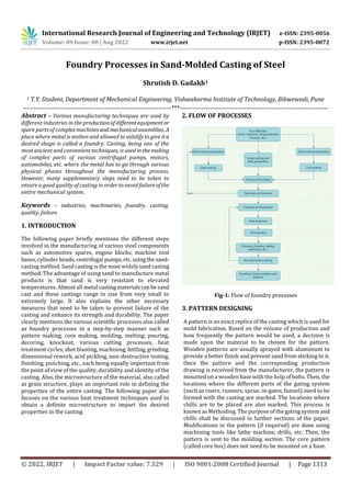
  • 1. International Research Journal of Engineering and Technology (IRJET) e-ISSN: 2395-0056 Volume: 09 Issue: 08 | Aug 2022 www.irjet.net p-ISSN: 2395-0072 © 2022, IRJET | Impact Factor value: 7.529 | ISO 9001:2008 Certified Journal | Page 1313 Foundry Processes in Sand-Molded Casting of Steel Shrutish D. Gadakh1 1 T.Y. Student, Department of Mechanical Engineering, Vishwakarma Institute of Technology, Bibwewadi, Pune ---------------------------------------------------------------------***--------------------------------------------------------------------- Abstract – Various manufacturing techniques are used by different industries in the productionofdifferentequipmentor spare parts of complex machinesand mechanicalassemblies. A place where metal is molten and allowed to solidify to give ita desired shape is called a foundry. Casting, being one of the most ancient and convenient techniques, is used inthemaking of complex parts of various centrifugal pumps, motors, automobiles, etc. where the metal has to go through various physical phases throughout the manufacturing process. However, many supplementary steps need to be taken to ensure a good quality of casting in order to avoid failureofthe entire mechanical system. Keywords – industries, machinaries, foundry, casting, quality, failure 1. INTRODUCTION The following paper briefly mentions the different steps involved in the manufacturing of various steel components such as automotive spares, engine blocks, machine tool bases, cylinder heads, centrifugal pumps,etc.usingthesand- casting method. Sand casting is the most widelyusedcasting method. The advantage of using sand to manufacture metal products is that sand is very resistant to elevated temperatures. Almost all metal casting materialscanbesand cast and these castings range in size from very small to extremely large. It also explains the other necessary measures that need to be taken to prevent failure of the casting and enhance its strength and durability. The paper clearly mentions the various scientific processes also called as foundry processes in a step-by-step manner such as pattern making, core making, molding, melting, pouring, decoring, knockout, various cutting processes, heat treatment cycles, shot blasting, machining, fettling,grinding, dimensional rework, acid pickling, non-destructive testing, finishing, punching, etc., each being equally important from the point of view of the quality, durability and identity of the casting. Also, the microstructure of the material, also called as grain structure, plays an important role in defining the properties of the entire casting. The following paper also focuses on the various heat treatment techniques used to obtain a definite microstructure to impart the desired properties in the casting. 2. FLOW OF PROCESSES Fig-1: Flow of foundry processes 3. PATTERN DESIGNING A pattern is an exact replica of the casting which is used for mold fabrication. Based on the volume of production and how frequently the pattern would be used, a decision is made upon the material to be chosen for the pattern. Wooden patterns are usually sprayed with aluminium to provide a better finish and prevent sand from sticking to it. Once the pattern and the corresponding production drawing is received from the manufacturer, the pattern is mounted on a wooden base with the help of bolts. Then, the locations where the different parts of the gating system (such as risers, runners, sprue, in-gates, funnel) need to be formed with the casting are marked. The locations where chills are to be placed are also marked. This process is known as Methoding. The purpose of the gating system and chills shall be discussed in further sections of the paper. Modifications in the pattern (if required) are done using machining tools like lathe machine, drills, etc. Then, the pattern is sent to the molding section. The core pattern (called core box) does not need to be mounted on a base.
  • 2. International Research Journal of Engineering and Technology (IRJET) e-ISSN: 2395-0056 Volume: 09 Issue: 08 | Aug 2022 www.irjet.net p-ISSN: 2395-0072 © 2022, IRJET | Impact Factor value: 7.529 | ISO 9001:2008 Certified Journal | Page 1314 4. CORE MAKING It is the process of forming a solid sand core so that the actual casting has the desired shaped cavity. Processes involved: A suitable composition for the sand-hardener mixture is chosen and prepared and the bottom half of the core box is filled with this mixture. Properly shaped metal rods are placed in the core box for providing additional strength to the core if required, depending on the size of the core. Thermocol or wax strips are then placed in the sand core at appropriate locations which melt during the oven preheating process thus, allowingthegastoescapefromthe core formed. This is very important to avoid crack formation and weakening of the core. A number ofchillsare placed in the core at appropriate locations so that they absorb some of the heat during the solidification process of molten metal and improve the cooling rate of the casting. Then the top half of the core box is placed and clamped to the bottom half to prevent core expansion during preheating. The sand mixture is also added in the tophalfto complete the core. Risers are placed wherever required in the core. Several voids are also created in the core to allow air to escape during preheating. Removal of excess sand takes place and the core is left undisturbed for a specified time to harden. The hardening time depends upon the type of hardener used. The core is sent for dressing and painting where it is spray painted with an inflammable mixture of paint and thinner which is set on fire so that the moisturein the core gets removed. The core is then placed in the preheating oven for 5-6 hours for further hardening and moisture removal. Then the core is sent to the core setting section where it is placed between the two halves of the mold before sending it to the pouring section. This is done by placing the core in the drag (bottom halfofthemold)and then placing and gluing the cope (top half of the mold) over it. 5. MOLDING It is the process of forming a mold of the desired shape that is further filled with molten metal to form the desired shaped casting. Processes involved: The mold is first divided into two halves viz. cope (top half) and drag (bottom half) and the two halves are formed separately. The mold pattern is placed into the mold box and accessories like the funnel,sleeves,L-blends,fire bricks, etc. are placed at appropriate locations for forming the gating system along with the casting. The sand-hardener- resin mixture is prepared withsuitablecompositionandthe mold box is filled with this sand mixture. The sand is then pressed tightly in the mold box and then allowed to solidify. The above processes can be done manually or with the help of machinaries depending upon the size of the mold. The hardened mold is then spray painted with paintandthinner mixture which is set on fire toremovethemoisturefromthe mold. Both the mold halves are passed through the preheating oven for further hardening and moisture removal. Then the corresponding core is placed in the drag and the cope is then inverted and placed over the drag and glued to it to form the complete mold which is then taken to the pouring section. Fig-2: Arrangement of complete mold 6. MELTING Scrap collected from various sources is first segregated as per the material grade. The scrap is first heated in an oven before sending it to the furnace so that it melts quicker. The furnace used is an induction furnace where a number of copper coils are present around the furnace and carry a huge current that creates an electric field and induces a current (Eddy current) in the scrap. This results in heating of the scrap and melts it. These furnaces are lined inside with refractory material to prevent melting of the furnace walls. Temperature of the furnace is maintained above the melting point of the material grade and the temperature of the molten metal is checked frequently using a thermocouple. Supply of Argon gas is provided through pipes at the bottom of the furnace. This gas, being inert, does not react with the metal but liftstheimpuritiespresent in it. These impurities are adsorbed by the slack powder sprinkled over the furnace. Specific amounts of Aluminium (ingot and shots) and Calcium Silicide are added to the molten metal for deoxidation of steel.Otherwise,reaction of the metal with oxygen may alter its properties. 7. POURING The molten metal is poured into certain ladles thatarelined inside with refractory material. The lining is done to prevent the ladles from melting as the temperature of the
  • 3. International Research Journal of Engineering and Technology (IRJET) e-ISSN: 2395-0056 Volume: 09 Issue: 08 | Aug 2022 www.irjet.net p-ISSN: 2395-0072 © 2022, IRJET | Impact Factor value: 7.529 | ISO 9001:2008 Certified Journal | Page 1315 molten metal is very high. Also, the ladle is first heated to a certain temperature before pouring molten metal into it to reduce the cooling rate of the metal. Otherwise, the molten metal may solidify even before reaching the entire mould thus, resulting in undesirable casting. Ladles are of two types viz., lip pouring and bottom pouring and have a steering to control the orientation of the ladle. Lip pouring ladles need to be tilted to pour the metal whereas bottom pouring ladles have an opening at the base that can the opened or closed by lifting or releasing a heavy rod called bottom pouring rod. Slack powder is then sprinkled on top of the ladle to remove impurities. The lid of the ladle is covered with an insulating material like glass wool to prevent heat losses to the surrounding.Moltenmetal isthen poured in the pouring basin and is further carried to the entire mold by the gating system (sprue, runners, in-gates, risers). Also, the gas in the mold is allowed to burn to prevent it from getting trapped in the mold. A riser (feeder) is used to prevent cavities in the casting that can form due to shrinkage of the metal on solidification. This is done by providing excess metal to the mold so that the cavity forms in the riser and not the casting. Anti-piping Compound (APC) powder is then added on top of the riser opening. This has the following advantages. Firstly, it prevents the sparks of the molten metal from reaching the workmen. Also, the metal in the riser is exposed to atmosphere because of which the cooling and solidification may start from the riser itself which is undesirable. Addition of APC breaks this exposure and the use of sleeves (made of exothermic material) keeps the metal intherisermoltenfor a longer duration than the casting. The casting cools at a comparatively faster rate due to the presence of chills. A small amount of metal is poured in a sample/test mold that is further used for inspecting the quality and properties of the casting 8. DECORING AND KNOCKOUT Both the test sample and the casting are allowed to solidify and then taken to the casting decoring area where the mold is broken down and the casting is removed. The pieces of sand mold are sent to the knockdown section by a motorized trolley where heavy vibrations of the container result in breakdown of the mold pieces to fine sand. This sand, being a mixture of various sands, is sent for purification and reuse. The casting can also be removed in the knockout section itself. The casting is then allowed to cool using air quenching or water quenching. 9. GAS CUTTING, POWDER CUTTING AND ROD GOUGING After the casting is cooled by quenching, it is taken to the cutting and gouging section to remove the unwanted parts that are not required in the casting i.e., funnel, risers, runners, gates, sprue, etc. Gas cutting: Mixture of oxygen and Acetylene is used to preheat the metal to its ignition temperature(for steel,700- 900 degree Celsius) but below its melting point. A jet of oxygen is directed into the preheated area initiating a vigorous exothermic chemical reaction between the metal and oxygen to form a metal oxide or slag. The oxygen jet blows away the slag enabling the jet to pierce through the material and continue to cut through it. Ignition temperature of the material must be lower than its melting point otherwise, the material would melt and flow away before cutting. Oxide melting point should be lower than that of the surrounding material so that it can be mechanically blown away by the oxygen jet. Oxidation reaction between the oxygen jet and metal must be sufficient to maintain the ignition temperature. Minimum gaseous reaction products should be formed so as not to dilute the cutting oxygen. Powder cutting: It is similar to gas cutting with an addition of iron powder to the oxygen jet. Stainless steel, cast iron, nonferrous metals form refractory oxides (Oxides whose melting point is higher than the material). Hence, powder is injected into the flame to form a fluid slag with low melting point. Acetylene, propane, MAPP (Methylacetylene- propadiene), propylene, natural gas arethecommonlyused fuel gases among which acetylene produces the highest flame temperature. Fig-3: Gas cutting
  • 4. International Research Journal of Engineering and Technology (IRJET) e-ISSN: 2395-0056 Volume: 09 Issue: 08 | Aug 2022 www.irjet.net p-ISSN: 2395-0072 © 2022, IRJET | Impact Factor value: 7.529 | ISO 9001:2008 Certified Journal | Page 1316 Fig-4: Powder cutting Rod gouging (Air carbon arc gouging): It is the process of removing material by means of heat generated by carbon arc. It removes excess material from casting and requires a carbon/graphite electrode,compressedair,standardpower source (like welding rectifier). An intense electric arc produced between tip of rod and workpiece cuts and melts the workpiece. Compressed air is usedfor blowingawaythe molten metal thoroughly from the casting surface. The metal is gouged (cut) in the airflow direction. It is used to remove excess weld beads also. The power source must have a constant current output characteristic otherwise,the high voltage current can cause the electrode tip to explode when touched to the workpiece. Copper coating is given to the graphite rod to reduce electrode erosion. Sometimes, water is poured simultaneously on the surrounding area to prevent it from cracking due to excess heat. 10. HEAT TREATMENT Process of heating the casting below its melting point to relieve internal stresses developed by forging, welding or during solidification itself. It is used to increase/decrease hardness of the material by achieving the desired grain structure. Processes involved: The heat treatment furnaces are first lined with insulating material (glass wool) on the inside to prevent heat losses. Heat treatment process is controlled by heat treatment furnace control panel. The furnacetemperatureisincreased to a specific set point in multiple cycles. This process is called as Ramping. The starting time of the process isnoted. Once the temperature of the furnaces reaches the desired maximum, it is held for a specific time. This processiscalled as Soaking. The cooling methodtobeusedispredefined.For air quenching, the number of running fans is already specified. Multiple burners are provided inside the furnace to maintain a uniform temperature throughout the casting. The temperature at different locations within the casting are measured using thermocouples. Fig-5: Basic types of heat treatment 10.1 Normalizing It involves heating the casting above recrystallization temperature (727 degrees for steel), then soaking for a specific time till the desired microstructure has been achieved and then cooling by air quenching. 10.2 Annealing This process involves heating the casting above recrystallization temperature(727degrees),soakingforthe specified time and then cooling by controlled furnace cooling. Air quenching cools at a faster rate than controlled furnace cooling. Faster the rate of cooling, finer is the grain structure hence, greater isthehardness.Normalizedcasting is harder as compared to annealed casting. Therefore, it is brittle and difficult to machine. Normalizing temperatures are usually higher than annealing temperatures. Both normalizing and annealing take place in 3 stages viz. recovery stage, recrystallization stage and grain-growth stage. Recovery stage: In this stage, the furnace or other heating device is used to raise the temperature of the material so that the internal stresses are relieved. Recrystallization stage: It involves heating the material above its recrystallization temperaturebut belowitsmelting point so that new grains are formed without any residual stresses. Grain-growth stage: The material is cooled at a specific rate causing new grains to develop after which the material will be more workable. After annealing and normalizing,various subsequent operationscanbecarriedouttoaltermechanical properties.
  • 5. International Research Journal of Engineering and Technology (IRJET) e-ISSN: 2395-0056 Volume: 09 Issue: 08 | Aug 2022 www.irjet.net p-ISSN: 2395-0072 © 2022, IRJET | Impact Factor value: 7.529 | ISO 9001:2008 Certified Journal | Page 1317 10.3 Hardening This process is done by heating the casting above recrystallization temperature (727 degrees), then soaking for a specific time and then cooling by dipping in water. Water cools the casting immediately and this results in a very fine grain structure. Hence, the casting becomes very hard and brittle and thus, difficult to machine. Water, brine, oil, etc. are used for solution treatment or solution quenching. 10.4 Tempering Normalized or water quenched (solution treated) castings are usually very hard. Hence, to reduce hardness and increase machinability, tempering is done. Here, casting is heated below recrystallizationtemperature, soaked for a specific time and then cooled at a specific rate to get the desired properties like hardness, grain structure, machinability, etc. (either by controlled furnace cooling or air quenching). After the heat treatment, the casting is sent for shot blasting and further processes. In the above processes, the casting is not heated to the final temperature in one step but rather in multiple steps by holding the casting at several intermediate temperatures. Fig-6: Ramping and soaking 11. SHOT BLASTING The undesirable black rusty layer developed on the casting after heat treatment gets removed by shot blasting. Very fine shots (made of aluminium, steel, etc.) are blasted with high velocity upon the casting with the help of multiple motors and corresponding impellers.The machine worksin a cyclic manner i.e., the shots falling down are collected and reused. The castings are taken to and removed from the machine with the help of hangers provided around the machine. The castings are kept in the shot blasting machine for 5-6 minutes. After the process, the casting becomes clean and greyish in colour. Also, any sand present in the casting gets removed and the voids on the surface get opened After this, the casting is sent for primaryinspection. If the defects are workable, only then the casting is sent for further processing or else it is rejected. 12. MACHINING/FETTLING/GRINDING The excess material remained on the casting after powder cutting and rod gougingisremoved bymachiningorfettling. The casting is machinedtodesireddimensionswiththehelp of various machining tools. The feet and flanges of the involute casing are machined to desired dimensions and finish. This is usually done for the castings that are to be exported. The casting is given a smooth, shinysurfacefinish by grinding operations. Then, the dimensions of the casting obtained are compared with the expected dimensions. Any dimension greater than the desired one is reduced by rod gouging and dimensions smaller than the desired ones are increased by welding. Then, the affected area is again given a smooth finish by grinding. 13. ACID PICKLING It is a surface treatment used to remove impurities such as stains, inorganic contaminants, rust or scale (oxide layer formed during hot working processes), etc. These are removed by reactions with mineral acids. As the damaged metal layer gets removed, a properly alloyed steel surface gets exposed providing a good corrosion resistant performance. Commonly used acids for pickling are sulphuric acid, hydrochloric acid, nitric acid, hydrofluoric acid, phosphoric acid. Hydrochloric acid is used in steel castings. Even though it is more expensive than sulphuric acid, it pickles at a faster rate while minimizing base metal loss. 14. NON-DESTRUCTIVE TESTING (NDT) Here, the casting goes through a number of quality tests without actually damaging or wasting the casting unlike tensile test, Brienell hardness test, etc.
  • 6. International Research Journal of Engineering and Technology (IRJET) e-ISSN: 2395-0056 Volume: 09 Issue: 08 | Aug 2022 www.irjet.net p-ISSN: 2395-0072 © 2022, IRJET | Impact Factor value: 7.529 | ISO 9001:2008 Certified Journal | Page 1318 Fig-7: Types of NDT 14.1 Liquid Penetrant Test The casting is first cleaned with red fluorescent paint. The paint is then allowed to settle and enter the surface pores and cracks for about 15 minutes. Then the entire casting is washed using water and solvent based cleaner and dried using air blower. A developer solution is sprayed on the casting which turns the entire casting white after sometime and exposes the fluorescent paint at locations where there are defects. Based on the severity ofthedefects,a decisionis made upon which defects to ignore and which ones to fix. Then the entire casting is washed and the defective locations are marked. The paint penetrated in the cracks and holes is removed by a water washable penetrant. 14.2 Magnetic Particle Test It is used for detection of surface and near-surface flaws in ferromagnetic materials and is primarily used for crack detection. The workpiece is magnetized and the magnetic flux is present predominantly inside the material. If there is any surface breaking flaw, the magnetic field is distorted, causing local magnetic flux leakage around the flaw. This leakage flux is displayed by covering the surface with very fine iron particles suspended in diesel. The particles accumulate at the regions of flux leakage,producinga build- up which can be seen visually even if the crack is very small and narrow. Thus, a crack is indicated as a visible line of iron powder or magnetic particles on the surface. Fig-8: Magnetic particle testing Magnetization can be produced by any of the following ways: By applying a permanent/electromagnet to the surface which is termed as magnetic flow By passing a large current through the overall specimen or it can be done locally by means of current prods By putting the component/specimen inside a current carrying loop By threading a current carrying bar through a hollow specimen The method of magnetization should produce a magnetic field such that the lines of force are at large angles to the expected direction of cracks to be detected. So, magnetization is done more than once in different directions. This can also be done using a combinationoftwo magnetic fields so that a swinging or rotating magneticfield can be produced which will detect a crack in any direction/orientation 14.3 Radiographic Testing Ionizing radiations are usedtopenetratethecross-sectional area of a casting and a piece of radiographic film is exposed. When discontinuities like cracks, gas, shrinkage or unfused chills or chaplets are present in a casting, the casting absorbs less radiation and more radiation reaches the film. This increased film exposure of the radiation ultimately produces an image of the discontinuityonthefilm.X-raysor Gamma rays are used to pass ionizing radiations through the casting.
  • 7. International Research Journal of Engineering and Technology (IRJET) e-ISSN: 2395-0056 Volume: 09 Issue: 08 | Aug 2022 www.irjet.net p-ISSN: 2395-0072 © 2022, IRJET | Impact Factor value: 7.529 | ISO 9001:2008 Certified Journal | Page 1319 Fig-9: Radiographic testing 14.4 Ultrasonic Testing This method uses high frequency sound waves to detect surface and subsurface discontinuities in castings. It can also measure the thickness of the casting at locationswhere the human hand or mechanical devices cannot reach. Here, an ultrasonic transducer transforms electrical energy into mechanical energy in the form of soundpressurewavesand the sound pulse thus, generated initiates at the transducer, travels through the casting and is reflected by boththe back wall of the casting and any discontinuities that may be present. The transducer senses the reflected sound wave and converts it to an electrical signal. The properties of the sound wave like transit time, amplitude and shape give an idea about any defects present. Fig-10: Ultrasonic testing Once the defective locations are marked, they are entirely removed by rod gouging and then welded. The excess of weld bead is removed by grinding and then the casting is sent for post weld heat treatment to relieve the stresses developed in the weld. After the post weld heat treatment (PWHT), the casting is again sent for shot blasting (for carbon steels) or grit blasting (for stainless steels). The material used for grit blasting is aluminium. The NDTs are performed again to ensure whether the defects have been fixed or not. Final finishing and acid pickling is done once again after all the defects have been removed. 15. Punching Large castings usually have heat numbers, pattern numbers and material grades embossed/extrudedonthemalong with the casting itself. However, some small castings need to be punched using metal stamping technique. The stamp has a specific dimension and has a letter or number embossed/extruded at its tip. The stamp of the correct size and letter must be chosen for punching. Holding the stamp vertically and hammering it 2-3 times creates a punch of the desired letter or number on the casting After all the above processes, the casting is finally ready for dispatch. 16. CONCLUSIONS This paper explains most of the processes involved in sand casting of steels. It takes into account not only the basic foundry processes of molding,scrapmeltingandpouring but also the additional steps taken to ensure a good quality of the overall casting. The properties of the casting highly depend on the quality of the mold and hence, a number of steps are taken to strengthen themoldandremoveanyvoids or moisture contained within it. Moreover, the process of scrap melting needs to be done carefully wherein additional alloying elements need to be added to obtain the desired composition of the material. This study also explains the basics of heat treatment of steel castings. However, more research needs to be done in order to obtain detailed information about the various physical phases and the corresponding microstructures of steel obtained during heat treatment. A number of transformations take place during heat treatment (martensite, austenite, bainite, pearlite, etc.) resulting in different mechanical properties of the component. A number of machining and finishing processes have been mentioned in the paper. However, the importance of each of them highly depends on the type of the component and the desired finish. Also, the availability of resources can affect the application of any process in a foundry. Many organizations, due to unavailability of space and resources, have to outsource in order to complete a given process.Also, the materials, tools and equipment used for different processes vary from company to company leading to
  • 8. International Research Journal of Engineering and Technology (IRJET) e-ISSN: 2395-0056 Volume: 09 Issue: 08 | Aug 2022 www.irjet.net p-ISSN: 2395-0072 © 2022, IRJET | Impact Factor value: 7.529 | ISO 9001:2008 Certified Journal | Page 1320 different quality of finished products. Moreover, the quality and volume of production also depend upon the extent to which manual labour and automation are implemented. REFERENCES [1] Design and Manufacture of Casting Pattern Plates by Rapid Tooling, A. Pereira, J. A. Pérez, J. L. Diéguez, G.Peláez,J. E. Are [2] Gating and Risering in Vertical Green Sand Moulds, N. W. Rasmussen, R. Aagaard and P. N. Hansen [3] A Study of Core and it’s types forCastingProcess,Dhairya S. Deore, Gunjan B. Chaudhari, Aman G. Chaturvedi,Shrikant Uttam Gunjal [4] Optimal feeder design in sand casting process by growth method, R. Tavakoli and P. Davami [5] Foundry quality control aspects and prospects to reduce scrap rework and rejection in metal casting manufacturing industries, T.R. Vijayaram, S. Sulaiman, A.M.S. Hamouda, M.H.M. Ahmad [6] Comparative Study of Air Carbon Arc GougingProcess on Sae 316 Stainless Steel, Anoop G Das, R. Abarna [7] Kinetics of Oxyfuel Gas Cutting of Steels, Adedayo, Adeleke Victor [8] Evaluation of Material Quality for Liquid-Penetrant Inspection Based on the Visibility oftheIndicatorPatternsof Flaws, Yu. A. Glazkov [9] Reliability and sensitivity of magnetic particle non- destructive testing in detecting the surface cracks of welded components