Study of Macro level Properties of SCC using GGBS and Lime stone powder
International Journal of Engineering Research and Development (IJERD)
1. International Journal of Engineering Research and Development
e-ISSN: 2278-067X, p-ISSN: 2278-800X, www.ijerd.com
Volume 8, Issue 10 (October 2013), PP. 01-08
Optimization of Plate Forming Process Using Ansys
Parametric Design Language
Sharangouda Patil1, Prof. Bharath S Kodli2
1
PDA College of Engg. Gulbarga,
Tejavi Techno Solution Bangalore.
2
Abstract:- Forming operation plays important role in manufacturing industry. Forming has the inherent
advantage of faster production rate with uniform to variable thickness formation. The objective of this work is
to obtain an optimal dimensions in the consideration of the influence of the metal flow deformation in Sheet
metal forming process. Finite element method in conjunction with optimization algorithm(APDL) was used to
analyze the effect of sheet metal size, fillet size and depth of forming on forming load in axisymmetric finite
element process. Finite element software (ANSYS) was used to Simulate forming process and then performing
a series of optimization iterations in order to obtain the optimal size and shape of punch and die geometry with
reference to punch load. The material used is aluminum metal matrix composite (AlMgSi matrix with 15% SiC
particles).
Keywords:- Plate Forging, Finite element method, Optimization
I.
INTRODUCTION
The finite element method is a numerical procedure that can be applied to obtain approximate solutions
to a variety of problems in engineering. Steady, transient, linear, or nonlinear problems in stress analysis, heat
transfer, fluid flow, and electromagnetism problems may be analyzed with the finite element method the idea of
representing a given domain as a collection of discrete parts is not unique to the finite element method. It is very
important to study the deformation behaviour of these materials to produce defect-free products.
Optimization of forming process design and forming process plan for various work materials can be
based on the maximization of production rate. rninimization of production cost. minimization of die cost.
maximization of product quality. The main factors effecting sheet and plate metal forming are die shape (angle,
bend radii), sheet or plate thickness, material properties and frictional condition at the plate/die interface
ANSYS Parametric Design Language (APDL) is a scripting language that can be used to build the model in
terms of variables. APDL is used to build the model parametrically to enable variables changes during the
optimization process, so that the best combination of design parameters is obtained for the specified objective
function, where in the present study, the objective function is the load required for the forging process.
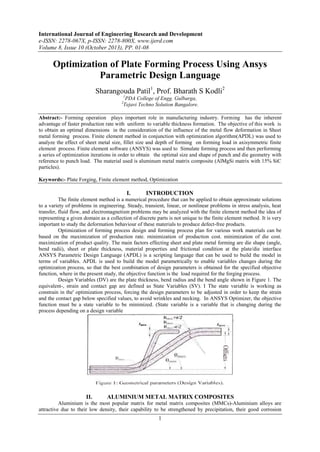
Design Variables (DV) are the plate thickness, bend radius and the bend angle shown in Figure 1. The
equivalent-, strain and contact gap are defined as State Variables (SV). I The state variable is working as
constrain in the' optimization process, forcing the design parameters to be adjusted in order to keep the strain
and the contact gap below specified values, to avoid wrinkles and necking. In ANSYS Optimizer, the objective
function must be a state variable to be minimized. (State variable is a variable that is changing during the
process depending on a design variable
II.
ALUMINIUM METAL MATRIX COMPOSITES
Aluminium is the most popular matrix for metal matrix composites (MMCs)-Aluminium alloys are
attractive due to their low density, their capability to be strengthened by precipitation, their good corrosion
1
2. Optimization of Plate Forming Process Using Ansys Parametric Design Language
resistance. high thermal and electric conductivity, and high damping capacity) ' Aluminium matrix composites
(AMCs) offer a large variety of mechanical properties depending gn the chemical composition of the aluminium
matrix. They are usually reinforced by continuous and discontinuous reinforcements. Discontinuous reinforced
AMCs are very altercative for their' isotropic mechanical, properties (higher than their unreinforced alloys) and
their low costs (low prices of some of the discontinuous reinforcement such as SiC particles or Al2O3
whiskers).
Figure 2 shows particulate and whiskers reinforcements. both are considered discontinues reinforcements.
MMCs cause particles and whiskers breakage, and normally result in cracks at the outer surface of the
work material. To avoid particles breakage which leads to cracks, the equivalent strain of the material must be
kept at low values.
III.
FINITEELEMENT MODEL
A circular plate made of aluminium metal matrix reinforced with 15 volume % silicon carbide particle
is going to be formed as shown in Figure 3. The metal plate is represented with a rectangle (a, b, c and d) and its
thickness is line (b-c). The upper and lower dies are represented with lines having two geometrical parameters
(Design Variables), the bending angle and the bending radius (+ or - half plate thickness depending on the bend
direction). The plate is represented with geometrical model consisting of assembly of finite element. Equations
relating the distribution of forces and displacements of the metal are established and the boundary condition and
die movement are imposed.
The cornponents of the model are shown in Figure 3. The Metal plate. is made of AlMgSi reinforced
with 15% SiC particles and has an initial thickness of 3 mm. Just half of the plate and the die is considered for
the analysis to reduce computational time and cost.
Table l: Isotropic Hardening characteristics of Plate material
Strain
Stress
0.003428
240
0.1
280
2
3. Optimization of Plate Forming Process Using Ansys Parametric Design Language
0.2
300
0.4
0.5
320
321
0.6
0.8
325
330
TABLE 1 : MATERIAL DATA
Three types of elements are used in the model. The plate is built up of two dirnensional 4-node
viscoplastic solid elements (ANSYS type VlSCOl06). A rigid to flexible contact pair is used to represents
die/plate contact. A two dimensional 2-node surface-to-surface contact element (ANSYS type CONTA l72) is
used to represent friction and sliding contact for the deformable surface of plate while a two dimensional target
element (ANSYS type TARGEI69) is used to model the rigid surface of the upper and lower die.
The axis of symmetry (line a-d) of the plate is constrained in (X) direction. The lower die is constrained
in (X) and (Y) direction. A displacement load is applied to the target element (TAR.GEI69) associated to the
lines representing the upper die profile in negative (Y) direction.
IV.
OPTNTZETION PROCESS
Optimization is a popular subject in finite element analysis, and is becoming more important goal in the
product development process analysis. This trend is facilitated by the ever-increasing computing power used to
solve analysis problems. For the design engineer, it is often the real end goal.
BASIC CONCEPT OF OPTIMIZATION
Optimization is quite an interesting aspect of engineering practice that cuts across all branches of
engineering. In the production sector, for example, the reduction of material (Figure 4) used in manufacturing is
possible when optimization is incorporated beforehand.
FIGURE 4: MATERIAL REDUCTION
Definition of Optimization
Optimization can be defined as the process of finding the conditions that give maximum or minimum
value of a „function‟. Where effort required or benefit desired for a given practical situation is expressed as a
„function‟ of certain design variables. This is illustrated in the Figure 5.
FIGURE 5: MINIMUM OR MAXIMUM VALUE OF AN EXPRESSION
3
4. Optimization of Plate Forming Process Using Ansys Parametric Design Language
The goal of the optimization process is to find the best solution for the given problem in the design
space defined to the optimization algorithm. Optimization model consists of three components: design variable
(independent variable), constraints (state variables or dependent variables) and the objective function (dependent
variable to be minimized). The optimization method used in the current study is called Sub-problem
approximation method. The method can be described as an advanced zero-order: method which requires only
the values of the dependent variables, and not their derivatives. To start the Optimization process, parameters
are first defined. They are referred as the design set. These parameters include design variables, state variables
and the model objective. Their values are modified throughout the Optimization process. Design variables are
independent quantities that are constrained within a specified range and are changed during the Optimization
analysis process.
FIGURE 6: THE OPTIMIZATION PROCESS
OBJECTIVE FTINCTION
The variable that is going to be defined as an objective function must be a state variable that is
changing during the process such as stress or strain or forming load. The objectives is the load required for the
forging process is taken as the objective function. Here the main work is to limit forging load in the process by
design optimizing the process for design variable and state variable.
V.
RESULTS AND DISCUSSION
The analysis is carried out for the initial geometry to find deformation, stress and contact pressure and
possible plastic strains. Large deformations are activated to capture the penetrations and plastic flows along
with contact simulations. Using commercial FE package (ANSYS). the FE model was build parametrically for
plate metal forming using APDL in order to enable ANSYS optimizer carry out a few optimization iteration by
changing the design 'variables (parameters) Table 2 shows ten design sets carried out by the optimization
algorithm' The set eight is the optimal one.
R1 –Fillet Radius T1: Thickness of the Sheet Metal
TH– Angle
H1- Sheet Metal depth of forming
4
5. Optimization of Plate Forming Process Using Ansys Parametric Design Language
Table 2
Fig 7 : iterations Vs Punch load
Fig 8 : Iterations Vs Thickness Variation
5
6. Optimization of Plate Forming Process Using Ansys Parametric Design Language
Fig 9 : Iterations Vs Plastic Strain
Fig 10 : Iterations Vs Fillet Variation
Fig 11: Objective function to Design variables
6
7. Optimization of Plate Forming Process Using Ansys Parametric Design Language
Fig 12: Objective Function to Plastic Strain
Maximum displacement of 28mm can be observed in the Sheet metal process. The sheet metal is
formed to the required shape by the punch movement. Maximum displacement can be observed at the inner
regions and minimum displacements in the outer regions.
FIG 13 : VONMISES STRESS RESULTS FOR INITIAL STRUCTURE
VI.
CONCLUSION & FURTHER SCOPE
•
Sheet metal forming process is simulated through APDL code. The code helps in obtaining number of
design sets giving possible deformations, stresses, plastic strains etc. Depends on requirements, a design set can
be choosen for the particular application. Also the complication in finding the load required for forming process
can be easily estimated and saves the designer time. From the results it is observed that sheet metal inclination,
thickness and fillet plays major role in deciding the safety and error free formed products.
FURTHER SCOPE:
•
Analysis process can be carried out with thermal effects.
•
Problem can be executed in three dimensional space
•
Impact analysis can be carried out to find behaviour of the members in contact.
•
Topology optimisation can be carried out to find optimum thickness required for
punch, die and blank holders
•
Composite usage can be checked.
7
8. Optimization of Plate Forming Process Using Ansys Parametric Design Language
BIBLIOGRAPHY
[1].
[2].
[4].
[5].
[6].
[7].
[9].
[10].
[11].
[12].
[13].
[14].
[15].
[16].
[17].
[18].
[19].
[20].
[21].
[22].
[23].
[24].
[25].
R.J.Duffin, E.L.Peterson and C.Zener, Geometric programming: theory and applications, Wiley, New
york, 1967.
G.B.Dantzig Linear Programming and Extensions, Princeton University Press.
R. A. Gettatly and R. H. Gallagher, “A procedure for automated minimum weight structural design,
Part
I - Theoretical basis, Part II - Applications,” Aero. Quart. Part I, Vol. 17, pp. 216-230 and pp.332-342,
1966.
M.M. Denn, Optimisation by variational methods, McGraw-Hill , New York 1969.
G.S.G. Beveridge and R.S. Schechter, Optimisation : theory and practice, McGraw-Hill, New York ,
1970.
J.L. Kuester and J.H. Mize, Optimisation techniques with FORTRAN, McGraw-Hill, New York, 1973.
M.J. Panik, Classical Optimisation: foundations and extensions, North-Holland Publishing Co.,
Amsterdam, 1976.
D. Koo, “ Elements of Optimisation” Springer-Verlag, New York, 1977.
D.G. Carmichael, Structural modeling and Optimisation, Ellis Horwood Chichester, 1981.
Morris,A.J. Foundations of structural optimization: a unified approach. John Wiley & Sons, 1st ed.,
UK, 1982
Y. M. Xie and G. P. Steven, “A simple evolutionary procedure for structural Optimisation,”
Comp.Struct. Vol. 49, pp. 885-896, 1993.
S.S. Rao – Optimization, Theory and Applications, Wiley inter-science, 1996
Ernst Hustedt, AMES Ltd. 1999, (Air New Zealand Engineering).
Jim Patterson (Hendrickson Trailer Suspension Systems). 2000.
Finite Element Procedures – Klaus-Jurgen Bathe, Prentice Hall of India Pvt. Ltd.- Sixth Edition 2002.
Introduction to the Finite Element Method, Desai/Abel – CBS publishers 2002.
Finite Element Analysis – C.S. Krishnamoorthy, Second Edn, TMH – 2002.
Hursha Narayan (Robert Bosch Corporation). 2002
Joe Metrisin (Florida Turbine Technologies, Inc.). 2002
Concepts and Application of Finite Element Analysis Rober D. Cook, David S – Joh Wiely & Sons
Pte. Ltd. Fourth Edition 2003.
Finite Elements in Engineering – Tirupathi R. Chandrupatla, Ashok D. Belegundu, Prentice – Hall of
India Pvt. Ltd, 2003.
Arrora, J. “Introduction to Optimum design”, 2 nd ed., Academic Press, 2004
8