Ijeee 20-23-target parameter estimation for pulsed doppler radar applications

Target Parameter Estimation for Pulsed Doppler Radar Applications Pratibha Jha1 S.Swetha2 D.Kavitha3 M.Tech Scholar (ECE), Dept of ECE Senior Assistant Professor & Associate Professor, Dept of ECE Aurora’s Scientific Technological & Research Academy Aurora’s Scientific Technological & Research Academy, JNTUH Aurora’s Scientific Technological & Research Academy, JNTUH Bandlaguda, Hyderabad, TS, India Bandlaguda, Hyderabad, TS, India Bandlaguda, Hyderabad, TS, India pratibhajha1001@yahoo.co.in swetha.sirisin@gmail.com kavitadevireddy@gmail.com Abstract- Conventional monostatic single-input single-output (SISO) radar transmits an electro-magnetic (EM) wave from the transmitter. The properties of this wave are altered while reflecting from the surfaces of the targets towards the receiver. The altered properties of the wave enable estimation of unknown target parameters like range, Doppler, and attenuation. However, such systems offer limited degrees of freedom. Multiple-input and multiple-output (MIMO) radar systems use arrays of transmitting and receiving antennas like phased array radars but while a phased array transmits highly correlated signals which form a beam, MIMO antennas transmit signals from a diverse set and independence between the signals is exploited Keywords: radar, OTA, MIMO, FHSS, DSSS, MISO

Recomendados
Mais conteúdo relacionado
Mais procurados
Mais procurados (19)
Semelhante a Ijeee 20-23-target parameter estimation for pulsed doppler radar applications
Semelhante a Ijeee 20-23-target parameter estimation for pulsed doppler radar applications (20)
Mais de Kumar Goud
Mais de Kumar Goud (20)
Último
Último (20)
Ijeee 20-23-target parameter estimation for pulsed doppler radar applications
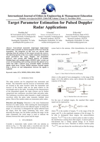
- 1. International Journal of Ethics in Engineering & Management Education Website: www.ijeee.in (ISSN: 2348-4748, Volume 1, Issue 11, November 2014) 20 Target Parameter Estimation for Pulsed Doppler Radar Applications Pratibha Jha1 S.Swetha2 D.Kavitha3 M.Tech Scholar (ECE), Dept of ECE Senior Assistant Professor & Associate Professor, Dept of ECE Aurora’s Scientific Technological & Research Academy Aurora’s Scientific Technological & Research Academy, JNTUH Aurora’s Scientific Technological & Research Academy, JNTUH Bandlaguda, Hyderabad, TS, India Bandlaguda, Hyderabad, TS, India Bandlaguda, Hyderabad, TS, India pratibhajha1001@yahoo.co.in swetha.sirisin@gmail.com kavitadevireddy@gmail.com Abstract- Conventional monostatic single-input single-output (SISO) radar transmits an electro-magnetic (EM) wave from the transmitter. The properties of this wave are altered while reflecting from the surfaces of the targets towards the receiver. The altered properties of the wave enable estimation of unknown target parameters like range, Doppler, and attenuation. However, such systems offer limited degrees of freedom. Multiple-input and multiple-output (MIMO) radar systems use arrays of transmitting and receiving antennas like phased array radars but while a phased array transmits highly correlated signals which form a beam, MIMO antennas transmit signals from a diverse set and independence between the signals is exploited Keywords: radar, OTA, MIMO, FHSS, DSSS, MISO 1. INTRODUCTION The radar systems can be categorized into monostatic and bistatic. The transmitter and the receiver of monostatic radar are located in the same location while the transmitter and receiver of the bistatic radar are far apart relative to the wavelength used in the radar. According to the characteristics of the transmitted signals, the radar systems can be further categorized into continuous waveform radar and pulse radar. The continuous waveform radar transmits a single continuous waveform while the pulse radar transmits multiple short pulses. Most of the modern radars are monostatic pulse radars. Detection and Ranging: Detection is the most fundamental function of a radar system. After emitting the electromagnetic waveform, the radar receives the reflected signal. To detect the target, it is necessary to distinguish the signal reflected from the target, from the signal containing only noise. After detecting the target, one can further calculate the range. In the radar community the word range is used to indicate the distance between the radar system and the target. 2. OTA DESIGN Consider a monostatic radar system with one antenna as shown in Fig. 1.1. The radar emits a waveform u(t) into the space. The waveform hits the target located in range r and comes back to the antenna. After demodulation, the received signal can be expressed as Figure 1.1: Basic Radar for Detection and Ranging where c is the speed of wave propagation, r is the range of the target, v(t) is the additive noise, and denotes the amplitude response of the target. Fig 1.2: Matched filter in the radar receiver For the case of multiple targets, the matched filter output signal can be expressed as where is the number of targets, is the range of the ith target, and is the amplitude response of the ith target. To be able to distinguish these targets, the autocorrelation function has to be a narrow pulse in order to reduce the interferences coming from other targets. A narrow pulse in time-domain has a widely spread energy in its Fourer transform and vice versa. Therefore to obtain a narrow pulse , one can choose the waveform u(t) so that the energy
- 2. International Journal of Website: www.ijeee.in (ISSN: 2348 of the Fourier transform of is widely spread. Fourier transform of the autocorrelation function Estimation of velocity: Besides detection and ranging, radar system can be used to further measuring the velocit object. For example, police speed radar measures the velocity of moving vehicles. The radar systems can also use velocity information to filter out the unwanted reflected signals. For example, for a radar system built to objects such as aircrafts or missiles, clouds will unwanted reflected signals. In radar community, this kind of unwanted signal is called clutter. In most of the c clutter can be very strong. Sometimes it may go up dB above the target signal. Fortunately, since the objects are usually still or moving slowly, one can use the velocity information to filter it out. Consider a monostatic radar system with one antenna and a moving target as shown in Fig. 1.4.The target with the speed v at an angle as shown in the radar system emits a narrowband waveform Here narrowband means the bandwidth of the signal is much smaller than the carrier frequency fc. The hits the moving target at range r and comes back to antenna. After demodulation, the received waveform expressed as Fig 1.3. : Illustration of Doppler effect where is the Doppler frequency, is the amplitude response of the target and v(t) denotes the noise i receiver. The Doppler frequency can be expressed as 3. MIMO CHANNEL MODELS MIMO systems are an extension of smart antennas sys Traditional smart antenna systems employ multiple a at the receiver, whereas in a general MIMO system m antennas are employed both at the transmitter and t Ethics in Engineering & Management Education Website: www.ijeee.in (ISSN: 2348-4748, Volume 1, Issue 11, November 2014) 21 is widely spread. Fourier is Besides detection and ranging, radar system can be used to further measuring the velocity of an easures the velocity of moving vehicles. The radar systems can also use the filter out the unwanted reflected signals. For example, for a radar system built to detect flying objects such as aircrafts or missiles, clouds will be the flected signals. In radar community, this kind of unwanted signal is called clutter. In most of the case, the clutter can be very strong. Sometimes it may go up to 30 to 40 dB above the target signal. Fortunately, since the clutter lly still or moving slowly, one can use the Consider a monostatic radar system with one antenna and a moving target as shown in Fig. 1.4.The target moves as shown in the figure. The . Here narrowband means the bandwidth of the signal is much smaller than the carrier frequency fc. The waveform hits the moving target at range r and comes back to the antenna. After demodulation, the received waveform can be is the amplitude response of the target and v(t) denotes the noise in the receiver. The Doppler frequency can be expressed as MIMO CHANNEL MODELS MIMO systems are an extension of smart antennas systems. Traditional smart antenna systems employ multiple antennas at the receiver, whereas in a general MIMO system multiple antennas are employed both at the transmitter and the receiver. The addition of multiple antennas at the transmitter combined with advanced signal processing algorithms at the t and the receiver yields significant advantage over smart antenna systems - both in terms of capacity and diversity advantage. A MIMO channel is a wireless link between M transmits and N receive antennas. It consists of MN that represent the MIMO channel coefficients. The m transmit and receive antennas could belong to a sin modem or it could be distributed later configuration is called distributed MIMO and communications. Statistical MIMO channel models off flexibility in selecting the channel parameters, te spatial correlations. Fig 1.4. : MIMO wireless MIMO System channel capacity long been regarded as “impairment” because it cause fading. To mitigate this problem, diversity techniq developed. Antenna diversity is a widespread form o diversity. Information theory has shown that with multipath propagation, multiple antennas at both transmitter can establish essentially multiple parallel channel simultaneously, on the same frequency band at the s radiated power. Antenna correlation varies drastically as a function of the scattering environment, the distanc transmitter and receiver, the antenna configuration Doppler spread. Recent research has shown that mult propagation can in fact “contribute” Channel capacity is the maximum information rate that can be transmitted and received with arbitrari probability of error at the receiver. A common repr of the channel capacity is within a unit bandwidth channel and can be expressed in bps/Hz. This representation is also known as spectral (bandwidth) efficiency. MIMO channel capacity depends heavily on the statis properties and antenna element correlations of the Representing the input and output of a me with the random variables X and Y respectively, the capacity is defined as the maximum of the mutual in between X and Y : A channel is said to memory less if the probability of the output depends only on the input at that tim conditionally independent of previous channel input Ethics in Engineering & Management Education November 2014) of multiple antennas at the transmitter combined with advanced signal processing algorithms at the transmitter and the receiver yields significant advantage over traditional both in terms of capacity and A MIMO channel is a wireless link between M transmits and N receive antennas. It consists of MN elements that represent the MIMO channel coefficients. The multiple transmit and receive antennas could belong to a single user modem or it could be distributed among different users. The later configuration is called distributed MIMO and cooperative communications. Statistical MIMO channel models offer flexibility in selecting the channel parameters, temporal and : MIMO wireless channel MIMO System channel capacity: Multipath propagation has long been regarded as “impairment” because it causes signal fading. To mitigate this problem, diversity techniques were developed. Antenna diversity is a widespread form of tion theory has shown that with multipath propagation, multiple antennas at both transmitter and receiver can establish essentially multiple parallel channels that operate simultaneously, on the same frequency band at the same total a correlation varies drastically as a function of the scattering environment, the distance between transmitter and receiver, the antenna configurations, and the Doppler spread. Recent research has shown that multipath propagation can in fact “contribute” to capacity. Channel capacity is the maximum information rate that can be transmitted and received with arbitrarily low probability of error at the receiver. A common representation of the channel capacity is within a unit bandwidth of the n be expressed in bps/Hz. This representation is also known as spectral (bandwidth) efficiency. MIMO channel capacity depends heavily on the statistical properties and antenna element correlations of the channel. Representing the input and output of a memory less channel with the random variables X and Y respectively, the channel capacity is defined as the maximum of the mutual information A channel is said to memory less if the probability distribution of the output depends only on the input at that time and is conditionally independent of previous channel inputs or
- 3. International Journal of Ethics in Engineering & Management Education Website: www.ijeee.in (ISSN: 2348-4748, Volume 1, Issue 11, November 2014) 22 outputs is the probability distribution function (pdf) of the input symbols X. MIMO Channel capacity: For the MIMO system, we have M antennas at transmitter and N antennas at receiver. We analyze the capacity of MIMO channel in two cases: Same signal transmitted by each antenna: In this case, the MIMO system can be view in effect as a combination of the SIMO and MISO channels. Different signal transmitted by each antenna: The big idea in MIMO is that we can send different signals using the same bandwidth and still be able to decode correctly at the receiver. Thus, it is like we are creating a channel for each one of the transmitters. The capacity of each one of these channels is roughly equal to: Fig 2.1 : MIMO Capacity for known Channel Fig 2.2 : MIMO Capacity for unknown channel 4. SPREAD SPECTRUM TECHNOLOGY Spread-spectrum techniques are methods by which a signal (e.g. an electrical, electromagnetic, or acoustic signal ) generated in a particular bandwidth is deliberately spread in the frequency domain, resulting in a signal with a wider bandwidth. These techniques are used for a variety of reasons, including the establishment of secure communications, increasing resistance to natural interference and jamming, to prevent detection, and to limit power flux density (e.g. in satellite downlinks). Spread spectrum techniques are fundamentally of two types. They are Direct sequence spread spectrum (DSSS) and Frequency hopping spread spectrum (FHSS). Both these techniques provide capabilities to resist interference and find applications in common and military communication. E (a) E freq freq (b) E (c) freq Figure (a) Normal signal spectrum, (b) spectrum of DSSS signal (c) spectrum of FHSS signal FHSS and DSSS are resistant to interference from conventional radio transmitters. The FHSS signal doesn't stay in one place on the band, FHSS can elude a jammer – (a transmitter designed to block radio transmissions on a given frequency). DSSS avoids interference by configuring the spreading function in the receiver to concentrate the desired signal but spread out and dilutes any interfering signal. Fig 1: (a) 10-Sparse Fourier Spectrum, (b) Time domain signal of length 300 with 30 samples, (c) reconstruction via l2-minimization, (d) exact reconstruction via l1-minimization.
- 4. International Journal of Ethics in Engineering & Management Education Website: www.ijeee.in (ISSN: 2348-4748, Volume 1, Issue 11, November 2014) 23 Figure 3. The amplitudes of Fourier coefficients of some FH signal within an observation interval in the condition of I-sparse 5. ADVANTAGES • Efficient and Robust Algorithm • Approximate detection of range and velocity • Signal reconstruction is not necessary. Therefore saves on the no of computations required. • Due to Compressive sensing the no of samples required and no of measurements are comparatively lesser compared to Nyquist theory of sampling. REFERENCES [1] M. I. Skolnik, IntroductiontoRadarSystems. NewYork:McGraw-Hill, 1980. [2] A.M.Haimovich,R.S.Blum,andL.J.Cimini,“MIMOradarwithwidely separated antennas,” IEEE Signal Process. Mag., vol. 25, pp.116–129, Jan. 2008. [3] J. Li and P. Stoica, MIMO Radar Signal Processing. Hoboken, NJ: Wiley, 2009. [4] J. Li and P. Stoica, “MIMO radar with colocated antennas,” IEEE Signal Process. Mag., vol. 24, pp. 106–114, Sep. 2007. [5] J. J. Zhang and A. Papandreou-Suppappola, “MIMO radar with frequency diversity,” in Proc. Int. Waveform Diversity Design (WDD) Conf., Orlando, FL, Feb. 2009, pp. 208–212. About the authors: Pratibha Jha received B.Tech degree in Electronics and communications Engineering from Jawaharlal Nehru Technological University, Hyderabad. She is currently pursuing the M.Tech degree with the Electronics and Communication Engineering at Aurora’s Scientific Technological & Research Acadamy, Affiliated to JNTU, Hyderabad, Telangana, India. Her research interests are Embedded Real Time Operating Systems, Image Processing and Digital System Design. Sirisanagandla Swetha received B.E in Electronics and communications Engineering from Sant Samarth Engg College, Affiliated to JNTU, Bandlaguda, Hyderabad and M.Tech in University College of Engineering, Tarnaka, Hyderabad, Telangana. Presently, she is working as Senior Assistant Professor at Aurora’s Scientific Technological & Research Acadamy, Affiliated to JNTU, Hyderabad, Telangana, India. Her research interests are Antennas, Microwaves and Radar D. Kavitha received B.E in Electronics and communications Engineering from MVSR EnggCollege,Affiliated to Osmania University, Nadargul, Hyderabad and M.Tech in GRIET, Affiliated to JNTU, Bachupally, Hyderabad, Telangana. Presently, she is working as Senior Assistant Professor at Aurora’s Scientific Technological & Research Acadamy, Affiliated to JNTU, Hyderabad, Telangana, India. Her research interests are VLSI.