
Recomendados
Mais conteúdo relacionado
Mais procurados
Mais procurados (19)
Destaque
Destaque (8)
Semelhante a International Journal of Computational Engineering Research (IJCER)
Semelhante a International Journal of Computational Engineering Research (IJCER) (20)
Último
Último (20)
International Journal of Computational Engineering Research (IJCER)
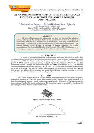
- 1. International Journal of Computational Engineering Research||Vol, 03||Issue, 7|| ||Issn 2250-3005 || ||July||2013|| Page 26 DESIGN AND ANALYSIS OF DS-CDMA DETECTED MULTIPATH SIGNALS USING THE RAKE RECEIVER SIMULATOR FOR WIRELESS COMMUNICATION. 1, Parisae.Veera Swamy, 2, M Hari Krishnam Raju 3, P.Suresh 1,2,3, M.Tech student,Asst. Prof.,ECE HOD Dept. of ECE,Sri Sunflower College of Engg.&Technology Lankapalli(Challapalli), Krishna (Dt), A.P - 521131 I. INTRODUCTION The number of multipath signals in the wireless channel is unknown and difficult to predict. The spread spectrum technology aims to spread the information signal over a wider bandwidth to make jamming and interception more difficult. , the number of multipath signals in the wireless channel is unknown and difficult to predict. A RAKE receiver allows each arriving multipath signal to be individually demodulated and then combined to produce a stronger and more accurate signal. The RAKE receiver in the IS-95A CDMA system uses three correlators and a searcher, while the TIA/EIA-95B CDMA system limits the number of correlators in the RAKE receiver to six. The searcher receives pilot signals for synchronizing the spreading code. Both of these systems have a fix number of correlators and leads to the RAKE receivers either containing an excessive number of correlators or that the receiver performs sub optimally. II. CDMA Code Division Multiple Access (CDMA) is a spread spectrum technique that uses neither frequency channels nor time slots. In CDMA, the narrow band message (typically digitized voice data) is multiplied by a large bandwidth signal, which is a pseudo random noise code (PN code). All users in a CDMA system use the same frequency band and transmit simultaneously. The transmitted signal is recovered by correlating the received signal with the PN code used by the transmitter. Fig:Code Division Multiple Access (CDMA) Fig: Spectrum of Wideband CDMA ABSTRACT Wireless cellular telephony has been growing at a faster rate than wired-line telephone networks. This growth has also been fueled by the recent improvements in the capacity of wireless links due to the use of multiple access techniques (which allow many users to share the same channel for transmission) in association with advanced signal processing algorithms. Code Division Multiple Access (CDMA) is becoming a popular technology for cellular communications. One form of CDMA called Direct Sequence CDMA (DS-CDMA) uses a set of unique signature sequence or spreading codes to modulate the data bits of deferent users.
- 2. Design And Analysis Of Ds-Cdma Rake… ||Issn 2250-3005 || ||July||2013|| Page 27 2.1.Direct-Sequence Spread Spectrum(DS-SS) The DS-SS technique is one of the most popular forms of spread spectrum. This is probably due to the simplicity with which direct sequencing can be implemented. Fig 4.13 shows the basic model and the key characteristics that make up the DS-SS communications system. In this form of modulation, a pseudo-random noise generator creates a spreading code or better known as the pseudo-noise (PN) code sequence. Each bit of the original input data is directly modulated with this PN sequence and is represented by multiple bits in the transmitted signal. On the receiving end, only the same PN sequence is capable of demodulating the spread spectrum signal to successfully recover the input data. Fig: Basic Model of the Direct-Sequence Spread Spectrum Communications System The bandwidth of the transmitted signal is directly proportional to the number of bits used for the PN sequence. A 7-bit code sequence spreads the signal across a wider frequency band that is seven times greater than a 1-bit code sequence, otherwise termed as having a processing gain of seven. Fig 4.14 illustrates the generation of a DS-SS signal using an exclusive-OR (XOR) operation. The XOR obeys the following rules: Fig: Generation of a DS-SS Signal with Processing Gain = 7 III. RAKE RECEIVER If in a mobile radio channel reflected waves arrive with small relative time delays, self interference occurs. Direct Sequence (DS) Spread Spectrum is often claimed to have particular properties that makes it less vulnerable to multipath reception. In particular, the rake receiver architecture allows an optimal combining of energy received over paths with different. It avoids wave cancellation (fades).if delayed paths arrive with phase differences and appropriately weighs signals coming in with different signal-to-noise ratios.The rake receiver consists of multiple correlators, in which the receive signal is multiplied by time-shifted versions of a locally generated code sequence. The intention is to separate signals such that each finger only sees signals coming in over a single (resolvable) path. Fig: Simple Block Diagram of DS-CDMA Transmitter and Receiver
- 3. Design And Analysis Of Ds-Cdma Rake… ||Issn 2250-3005 || ||July||2013|| Page 28 IV. SIMULATION 4.1.GUI for simulation of CDMA When we run the rake_cdma_gui.m then this will open this gui the simulation will perform on this gui this GUI show the information about the no of bit error in simulation with and without rake , show the user data and received data, user have to put information about the no of user , user to simulate and attenuation factor and after simulation we will get figure of transmit data and received data , number of bit error in received data for both RAKE and without RAKE receiver , this result show the comparison between simulation with and without RAKE receiver in cdma Fig: GUI for Simulation of CDMA 4.2.GUI for CDMA simulation without RAKE when attenuation factor is 1 When we push the push button simulation without RAKE button with attenuation factor 1 then the transmitting data and receiving data, no of bit error , the attenuation factor is one in this condition bit error is zero this show that the power level of transmitting data is high then the bit error in receiving data is less. Fig: GUI for CDMA Simulation without RAKE When Attenuation Factor is 1 4.3.GUI for CDMA simulation with RAKE when attenuation factor is 1 When we push the push button simulation with RAKE button with attenuation factor is 1 then the transmitting data and receiving data, no of error no of trial . the attenuation factor is one in this condition bit error is zero this show that the power level of transmitting data is high then the bit error in receiving data is less. Fig: GUI for CDMA Simulation with RAKE Reciever 4.4.Multipath received signal When we push the push button simulation without RAKE button or simulation with RAKE with attenuation factor is 1 then the multipath receiving data.
- 4. Design And Analysis Of Ds-Cdma Rake… ||Issn 2250-3005 || ||July||2013|| Page 29 Fig: Multipath Received Signal 4.5Command window after simulation with RAKE Command window of Matlab after simulation with RAKE will show information about the receiving data err1 is the receiving data which we get from path one and err2 is the receiving data which we get from path two. Fig: Command Window after Simulation with RAKE 4.6.Command window after simulation with RAKE Command window of Matlab after simulation with RAKE will show information about the receiving data the err3 is the receiving data which we get from path three the mxco1, mxco2 and mxco3 is the total sum of err1, err2 and err3 we will take maximum output of three. Fig: Command Window after Simulation with RAKE 4.7.Command window after simulation without RAKE Command window of Matlab after simulation without RAKE will show information about the receiving data the deco_data is the output data and err is show the bit error in receiving data. V. CONCLUSION We have developed a simulator made in our project, we have shown how rake receiver in used for CDMA to decease bit error due to multipath interferences. it can simulate a CDMA encoding and decoding process, the data is assumed to be travelled through different path, the effect of different path and CDMA is
- 5. Design And Analysis Of Ds-Cdma Rake… ||Issn 2250-3005 || ||July||2013|| Page 30 considered to generate the multipath effect the data is pass through the different path and assumed at receiver end just before the decoder .to avoid the multipath effect RAKE receiver is used the RAKE receiver concept is introduced in the decoding process.Detection of DS-CDMA signals using the RAKE Rx, results in performance improvement compared to correlator Rx. VI. REFERENCE [1] Peter Flanagan, “Personal Communications Services: The Long Road Ahead,” Telecommunications, February 1996. [2] http://wireless.per.nl/reference/chaptr05/cdma/rake.htm. [3] W. C. Y. Lee, “Overview of Cellular CDMA,”IEEE Trans. On Vehicular Technology, Vol. 40, no. 2, pp. 291-302, May 1991. [4] R. A. Cameron and B. D. Werner, “An Analysis of CDMA with Imperfect Power Control,” Proceedings of 42nd IEEE Vehicular Technology Conference, Denver, CO, pp. 977-980, 1992. [5] R. Lupus and S. Verdi, “Linear Multiuser Detectors for Synchronous Code Division-Multiple-Access Channels,” IEEE Trans. Info. Theory, vol. 35, no.1, pp. 123-136, Jan. 1989. [6] K.Murali.Krishna, Abhijit Mitra and Cemal Ardil” A Simplified Single Correlator Rake, Receiver for DMA Communications” International Journal of Information Technology Volume 2 Number 4 2005. [7] P. Jung, P. W. Baier, and A. Steil, “Advantages of CDMA and Spread Spectrum Over FDMA and TDMA in Cellular Mobile Radio Applications,” IEEE Transactions Vehicular Technology,Vol. 42, no. 3, pp. 357- 364, August 1993 [8] Electronic Industries Association, “Cellular System Dual-Mode Mobile Station Base Station Compatibility Standard,” IS-54, May 1990. [9] K. S. Gilhousen, “On the Capacity of a Cellular CDMA System,”IEEE Transactions on Vehicular Technology, Vol. 40, no. 2, pp. 303-311,May 1991. [10] Electronic Industries Association, “Widband Spread Spectrum Digital Cellular System Dual Mode Mobile Station - Base Station Compatibility Standard,” IS-95, April, 1992 [11] J. C. Liberti and T. S. Rappaport, “Analytical Results for Capacity Improvements in CDMA,” IEEE Transactions on Vehicular Technology, Vol.43, No. 3, pp. 680-690, August 1994.