1. Module-6 Dial indicator
Review Questions Solved
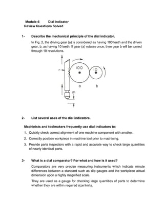
1- Describe the mechanical principle of the dial indicator.
In Fig. 2, the driving gear (a) is considered as having 100 teeth and the driven
gear, b, as having 10 teeth. If gear (a) rotates once, then gear b will be turned
through 10 revolutions.
2- List several uses of the dial indicators.
Machinists and toolmakers frequently use dial indicators to:
1. Quickly check correct alignment of one machine component with another.
2. Correctly position workpiece in machine tool prior to machining.
3. Provide parts inspectors with a rapid and accurate way to check large quantities
of nearly identical parts.
3- What is a dial comparator? For what and how is it used?
Comparators are very precise measuring instruments which indicate minute
differences between a standard such as slip gauges and the workpiece actual
dimension upon a highly magnified scale.
They are used as a gauge for checking large quantities of parts to determine
whether they are within required size limits.
2. 4- Describe how a dial comparator is used?
The comparator shown in Fig. 12 has a rigid construction, a large easily visible
indicating scale. An adjustable worktable is provided and the indicating head can
be raised or lowered by means of the large diameter back screw pillar. Range
magnification is 300-500.
5- Explain the difference between the balanced dial indicator and the
continuous reading type?
1. The balanced type has figures in both directions from the zero as in Fig. 3.
2. The continuous reading type is numbered continuously as in Fig. 4.
Figure 3 Balanced Typed Figure 4Continuous Typed
6- List several kinds of dial indicating gauges and briefly describe their use.
1. Dial indicator gauges
Numerous special gauges are equipped with dial indicators. These gauges are
used widely for determining whether parts are within required size limits.
2. Dial indicating depth gauges
Fig. 7 is used for gauging or testing the depth of holes, slots, shoulders,
recesses, and keyways. Extension points increase the measuring depths at
which the gauge may be used.
3. Dial indicating snap gauges
Fig. 8, are used for gauging diameters of parts to determine whether they are
within the size limits specified. In use, the gauge is snapped over the diameter of
3. the part being gauged. Snap gauges are efficient for checking parts which are
produced in large numbers, and they are available in a wide range of sizes.
4. A retractable contact snap gauge
Is shown in Fig. 9, the contactor point is opened with a button located
conveniently for thumb operation. This type of gauge is available in sizes which
gauge, within certain ranges, from 0 -112 mm (0″ - 4 1/2″).
5. Dial indicating caliper gauges
Fig. 10, have revolution counters which make it possible to measure directly
through their complete range of 75 mm (3”). Calipers of this type are available
with 0.02 mm (0.0008”) graduations.
6. Dial indicating hole gauges,
Fig. 11, are used to gauge or test holes for size, taper, out-of-roundness, or other
irregular conditions. They are available in a wide range of sizes.