2. American Institute of Aeronautics and Astronautics
2
The Doak VZ-4, Fig. 2, was proposed to the US
Army’s Army Transportation and Research Engineering
Command in 1950. The aircraft had a two seats, a single
840 horsepower turboshaft engine driving two 4.0 foot
diameter rotating ducted propellers on each wingtip, and
engine exhaust air the exited the airplane at the tail through
horizontal and vertical vanes. See Figure 3. The exhaust
air passing through the vanes provided pitch and yaw
control for the vehicle. The ducted fans had fixed blade
angles and thus vertical thrust and roll control was
provided by vanes behind each fan.
The Doak VZ-4 first flew in 1958 and within three
months the aircraft had made successful transitions from
hovering flight, to forward flight, and back to hovering
flight. The aircraft was later upgraded with a 1,000
horsepower engine for improved performance. With a
gross weight up to 3,200 pounds and the upgraded engine,
the VZ-4 had a power loading of 3.2 lb/hp and a disk
loading of 127 lb/ft2
. The rotational tip speed of each
propeller was 1,000 feet per second.
In the Doak Company final report2
,
The aircraft was found to be capable of performing
vertical take-offs, conversion to normal airplane flight,
conversions from normal airplane flight to hovering
flight, and vertical landings. The aircraft was determined
to be a feasible configuration for the VTOL mission,
although deficiencies were noted in the hovering lateral
and directional control systems and large longitudinal
trim changes were encountered in decelerating
conversions.
Similar issues were noted by both the Army and
NASA3
.
Primary issues were lack of control power particularly
on approach to landing with the engine at reduced power
settings. With reduced engine power, the engine exhaust
was reduced and thus the control power in pitch and yaw
from the rear vanes was reduced. The reduced control
power occurred at the same phase of flight when pitch control power requirements were at a maximum as the
aircraft transitioned from wing borne flight to fan borne flight. Maximum speed was limited due to the use of fixed
blade angles on the propellers which was a design decision to simplify fabrication of the research aircraft. Future
aircraft were intended to have controllable pitch propellers.
The Doak VZ-4 prototype exists today at the US Army
Transportation Museum in Fort Eustis, Virginia.
The Bell X-22, Fig. 4, was originally developed as a
prototype aircraft for the US Navy starting in 1962. The
aircraft had four 1,050 horsepower turboshaft engines
connected through a complex drive system to four 7.0 foot
diameter rotating ducted propellers on the tips of the
forward canard and the aft main wing. First flight
occurred in March 1966 followed by a crash due to a
failure in one of the propeller controls in August. A
second prototype flew in August 1967 and successfully
flew until 1988 being operated by Cornell Aeronautical
Laboratory. The surviving prototype is located at the
Niagara Aerospace Museum, New York.
With a gross weight up to 18,420 pounds, the X-22 had
a power loading of 4.4 lb/hp and a disk loading of 119
Figure 2. Doak VZ-4 VTOL Research Aircraft. The
Doak VZ-4 was a single turboshaft, twin ducted fan
aircraft that first flew in 1958 and successfully
transitioned from hover to forward flight and back.
Figure 3. Doak VZ-4 Tail Control Vanes. Horizontal
and vertical vanes located in the engine exhaust air at
the tail of the VZ-4 provided pitch and yaw control.
Control power at low engine power settings was
limited.
Figure 4. Bell X-22 Prototype VTOL Aircraft. The
Bell X-22 had four turboshaft engines, four rotating
ducted propellers, and a mechanical drivetrain
connecting all engines with all fans. The aircraft was
tested with a variable flight control and stabilizer
system.
Downloaded
by
NANYANG
TECHNOLOGICAL
UNIVERSITY
on
June
20,
2016
|
http://arc.aiaa.org
|
DOI:
10.2514/6.2016-3610
3. American Institute of Aeronautics and Astronautics
3
lb/ft2
. With a single engine inoperative, the engines had a military rating of 1,250 horsepower and thus the power
loading was 4.9 lb/hp. The rotational tip speed of each propeller was 975 feet per second.
The aircraft had a Stability Augmentation System and a separate experimental Variable Stability System that
allowed experimenting in flight with different control configurations in an early precursor to Fly-By-Wire (FBW)
systems. A few interesting quotes from the final flight test report4
:
Vertical takeoffs and landings are easily performed. All hovering maneuvers are much easier to perform than in most
helicopters.
Hovering has satisfactorily been accomplished without the Stability Augmentation System (SAS) although the pilot
workload is increased. STOL landings without the SAS are accomplished with ease.
Other comments in the final report include “High thrust to weight ratio (T/W = 1.35 standard day) allows an
engine-out VTOL capability on a hot day,” “Large transition envelope provides wide latitudes of handling in
transition,” and “High rates of descent capability at very slow speeds makes it possible to evaluate high approach
angles independent of fuselage attitude.” Clearly the aircraft
had promise, but was not selected for future development as
the US military spending was focused on the war in Vietnam.
Several ducted fan configurations were evaluated, all
with additional features to eliminate the limited control
capability of the two duct VZ-4 configuration. A minimum
of three fans were identified in order to provide sufficient roll
and pitch control power. Fans in various locations on
wingtips and alongside the fuselage were evaluated including
retractable aft fans in both open and ducted configurations.
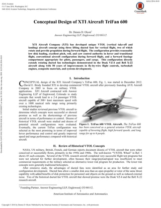
Eventually, the TriFan configuration was selected, Fig. 5.
The two wing fans were located inboard on the wing and
slightly forward of the wing. This location provided a short,
and thus light, driveshaft system. The body fan also allowed
for a short driveshaft and upper doors and lower vanes
allowed the fan to be completely enclosed to reduce drag in
forward flight. The resulting “tripod” fans in a close-coupled
configuration required a swept wing in order to place the
approximate mean aerodynamic quarter chord at the area
weighted center of the three fans.
III. Conceptual Sizing
One of the most important conceptual design sizing calculations for a VTOL aircraft is the ability of the selected
engine to turn power into lift based on the geometry of the lifting disks. A classic reference for this calculation for
an open disk is found in Ref. 4 and through some
manipulation can be expressed as thrust available based on
input power, total disk area, air density, disk solidity, and
several assumed parasite drag and induced drag coefficients.
For ducted fan configurations, an estimate is typically
made for the extra thrust provided by the use of a duct
relative to an open rotor. After studying multiple NASA and
other published papers, XTI settled on an extra 20% static lift
to be gained through the use of a duct.
An MS Excel spreadsheet was developed to quickly
determine the available thrust based on several potential
engines, number of lifting disks, use of a duct or not, and
disk diameters, Fig. 6. This tool allowed quick estimates to
be made of the potential maximum lift and thus maximum
aircraft weight available for different conceptual
configurations based on selected engines. This tool showed
the advantages in lift capability obtained by using three large
fans instead of just two. As will be discussed later, the three
fan configuration also provided improved pitch authority
Figure 6. Single Fan Static Lift Calculation. The
static lift available from a rotor with constant power at
different diameters. Enhanced lift from a duct is also
shown, along with the predicted average downwash
velocity through the lifting disk.
Figure 5. TriFan 600 Top View.
Downloaded
by
NANYANG
TECHNOLOGICAL
UNIVERSITY
on
June
20,
2016
|
http://arc.aiaa.org
|
DOI:
10.2514/6.2016-3610
4. American Institute of Aeronautics and Astronautics
4
compared with the two fan Doak configuration and should be similar to the well behaved four fan X-22
configuration.
After reducing the number of conceptual configurations, further analysis was completed at varying altitudes and
temperatures as they affected engine power and air density and thus impacted lift capability.
A typical business aircraft has a considerable range in aircraft center of gravity (CG) when transitioning from
single pilot to full payload. A common acceptable center of gravity range is between 10 and 30% of the mean
aerodynamic chord of the wing and this was used for initial sizing. When in hovering flight at the forward CG, the
forward fans in a multi-fan configuration are more highly
loaded. At aft CG, the aft fan(s) are more highly loaded.
Again, the surviving conceptual configurations were
evaluated at forward and aft CG conditions in hovering
flight.
This analysis in particular drove the three fan
configuration of the TriFan 600 and especially the large
size of the aft fan. At forward CG, the two wing fans
carry approximately 40% of the weight each and the body
fan only 20% of the weight. At aft CG, the two wing fans
carry 30% each and the body fan 40%. This nice balance
requires similar performance capability between the wing
and body fans and thus similar design goals.
The conceptual design of the actual duct and fan
geometry was developed by Continuum Dynamics, Inc.
(CDI). Using custom helical vortex lattice (HVL) codes
developed by CDI, Fig. 7., the duct shape and fan were
optimized for a balance between hovering lift and high
efficiency and low drag at high forward speeds. The HVL
code has been calibrated against multiple sets of test data,
and in particular for the TriFan 600 configuration, the X-
22 NASA data provided particularly relevant test
information. The TriFan configuration has significantly
reduced high speed drag compared with the X-22 with
only a modest reduction in static lift.
The initial optimized duct and fan, along with the
remainder of the selected TriFan configuration were
analyzed by Helden Aerospace using TETRUSS/USM3D
compressible Navier-Stokes computational fluid dynamics
code, Fig. 8. Multiple analysis conditions were completed
for the aircraft in hover, transition, and forward flight
configurations with varying levels of engine power and fan
swirl. Multiple control surface positions were analyzed to
obtain control power coefficients. Multiple yaw vane
configurations and deflection angles were analyzed to
determine the maximum lateral velocity of the aircraft
when in hover configuration. CFD studies are continuing.
The HVL and CFD analysis confirmed that the 20%
static thrust from the duct is a conservative estimate, also supported by published NASA report.
IV. Hover and Cruise Control
Many VTOL aircraft have suffered from insufficient control power, particularly during hover and transition
flight modes. XTI dedicated significant effort in the Conceptual Design Phase to evaluate each concept for control
authority in all axes.
A. Hover Control
The two turboshaft engines are connected to the three ducted fans with a mechanical gearbox that requires the
three fans to operate at a fixed relative speed. The two wing fans rotate in opposite directions, and the body fan
Figure 7. CDI Helical Vortex Lattice Analysis
Model. The CDI helical vortex lattice analysis model
includes a detailed loft of the external duct and lifting
fans along with a free trailing vortex.
Figure 8. Helden CFD Analysis Model. The TriFan
600 configuration was evaluated in hover, transition,
and forward flight configurations with varying power
levels, swirl angles, and control surface angles.
Downloaded
by
NANYANG
TECHNOLOGICAL
UNIVERSITY
on
June
20,
2016
|
http://arc.aiaa.org
|
DOI:
10.2514/6.2016-3610
5. American Institute of Aeronautics and Astronautics
5
rotates at a slightly higher speed due to its slightly smaller diameter. The engine FADEC controls maintain a
constant engine speed during hovering and transitional flight.
During hovering flight, pitch and roll control are provided by varying the propeller blade angles on each of the
three ducted fans or shrouded propellers (note that I use the terms interchangeably). Vertical lift is also controlled
by varying the propeller blade angles together. As extra power is required to maintain fan rotational speed, the
engine FADEC provides more fuel to the engines.
Yaw control is nominally provided by two vanes located under the body fan. Initial studies suggest this may
only provide control power for lateral velocities in the low 20 mph range, so further studies are evaluating rotating
the wing ducted fans or adding controllable vanes behind the wing ducted fans to provide more yaw control
authority.
The three blade angles and yaw vanes will be controlled by a fly-by-wire (FBW) flight control system that will
simplify hovering flight including inertial and GPS station keeping modes. FBW technology is considered a key
advancement that will allow the TriFan 600, and any VTOL aircraft, to be easily controlled by a typical pilot.
B. Cruise Control
The TriFan has conventional elevator, aileron, and rudder flight controls for high speed forward flight. These
controls reduce the likelihood of unforeseen control issues in the airplane mode flight test program.
XTI is still evaluating whether these controls will be conventional mechanical controls or FBW controls
integrated with the hover flight controls. Regardless of which approach is selected, the airplane and hover flight
controls will be directed by the pilot and copilot conventional control stick, rudder pedals, and helicopter collective.
During low speed or hovering flight, initial studies suggest that moving aircraft control surfaces will have little
effect on the control of the aircraft.
C. Transition Control
Initial studies indicate a relatively smooth transition from hover to forward flight and back with a pitching
moment “hump” in the low to middle transition speed range. Although a fixed mechanical interconnection between
the hover and airplane controls appears to provide an acceptable control solution, the FBW hover control solution
should make the pitching moment transparent to the pilot.
V. Predicted Performance
Hovering flight performance was discussed previously.
Cruise speed and range calculations were completed using traditional aircraft performance methods. Aircraft
drag was predicted using an area and drag coefficient buildup method and correlated with high speed Navier-Stokes
CFD analysis with added drag counts for antennas, gaps, excrescence, etc. Previous experience with light business
jets has demonstrated through flight test that a typical six seat aircraft will have a drag area of between 4 and 7
square feet. The base TriFan 600 without the ducted fans and stators has a similar drag area.
The large ducts and stators increase the drag area approximately 30%, significantly reduced maximum speed and
range. Compared with other early configurations evaluated by XTI, this drag penalty is less than most other
configurations in terms of added drag or reduced propeller efficiency for large rotors at high speeds.
Engine power and fuel efficiency estimates were provided by engine manufacturer performance decks including
factors for inlet efficiency, electrical power requirements, and bleed air removed to provide cabin pressurization.
Maximum cruise speed is estimated to exceed 340 KTAS at 28,000-32,000 foot altitudes, with slightly reduced
speeds at higher altitudes but at greatly improved fuel efficiency.
Aircraft drag and engine performance data were combined in a range calculator based on NBAA IFR methods
including allowances for engine start, taxi, in our case hover and initial transition, climb to several intermediate
altitudes, cruise at various speed/power settings and altitudes, descent, approach, missed approach, alternate
destination, hover, landing, and reserve fuel. Current range calculations for the TriFan 600 on a standard, sea-level
day with a pilot and three passengers exceeds 1,500 nautical miles.
Unique to helicopters and VTOL aircraft compared with conventional business jets are the significant weight
reductions at hot, high altitude departure and destination locations. The reduced engine power on a hot, high day,
combined with the reduced lift efficiency with low density air, results in greater weight reductions in order to meet
single engine hover requirements or Category A performance standards. Reduced takeoff weight results in less fuel
available at a constant payload and thus reduced range.
Downloaded
by
NANYANG
TECHNOLOGICAL
UNIVERSITY
on
June
20,
2016
|
http://arc.aiaa.org
|
DOI:
10.2514/6.2016-3610
6. American Institute of Aeronautics and Astronautics
6
Note that with the high relative power available, conventional runway takeoffs or short takeoffs with the body
fan covered and the wing fans at 45° allow a return to the maximum gross weight of the airplane and thus full fuel
even on hot, high days if a small airport is available at the departure location.
VI. Next Steps
Preliminary Design on the TriFan 600 has commenced on several fronts.
First, XTI will continue CFD analysis on the baseline configuration including expanding the transition envelope
analysis. These results will be incorporated in a high fidelity flight control and performance model which
incorporates rotor wake, multi-body aerodynamics, unsteady airloads, and engine and drivetrain dynamics. This
effort will also generate an engineering flight simulator to further refine the flight control laws.
Second, XTI will build a 10% subscale flying remote-controlled aircraft to demonstrate the basic configuration
of the aircraft including aerodynamic behavior during transition to and from hovering and forward flight, as well as
basic flight control laws. The flight control behavior of this model will be compared with the output from the high
fidelity flight control model noted above and any discrepancies identified and further studied.
Third, XTI will build a 65% subscale manned flying technology demonstrator. This demonstrator will have two
pilot seats, a single turboshaft engine and a mechanical flight control system supplemented by a digital flight control
system. The digital flight control system actuators will move or “influence” the mechanical flight control system
and even be capable of autonomous flight. This digital flight control system has been previously demonstrated on
an optionally piloted helicopter. Advantages of this approach, with a manned hybrid mechanical-digital system are
ease of operations in the US airspace system and a completely mechanical system in the event of a digital system
failure. As demonstrated on a previous program, this approach allows rapid improvements on the flight control laws
in a safe, controlled manner. The propulsion test system for this vehicle, including engine, fuel system, reduction
gearbox, driveshafts, and rotating ducted fans should be operational within the next 18 months.
Finally, XTI has started discussions with key vendors on the full scale TriFan 600 Proof-of-Concept (POC)
vehicle. This vehicle is intended to have the engines, complete drivetrain system, and fly-by-wire flight controls
planned for use in the certified aircraft. Ground testing and flight testing of the full scale POC will help confirm the
final aerodynamic configuration and system performance of the aircraft early in the certification process to minimize
the number of development issues commonly encountered on a program like this.
VII. Conclusion
XTI Aircraft Company has developed a unique VTOL aircraft concept that balances the hover and high speed
requirements of a commercial VTOL aircraft with a bias toward high speed, long range cruise capabilities. The
ducted fans provide enhanced static thrust capability relative to open propellers and also provide benefits in
minimizing hazards to personnel and ground equipment as well as reducing radiated noise. The three ducted fans
also provide excellent roll and pitch control relative to many other VTOL configurations. These benefits will be
demonstrated in the next phases of the program including a 10% subscale flying remote-controlled model and a 65%
subscale manned flying technology demonstrator.
Acknowledgments
XTI Aircraft Company thanks Todd R. Quackenbush of Continuum Dynamics, Inc. in Ewing, New Jersey,
Helden Aerospace Corporation of Acworth, Georgia, and Scion Aviation, LLC of Fort Collins, CO for their support
on the Conceptual Design and early Preliminary Design of the TriFan 600.
References
1
“V/STOL Aircraft and Propulsion Concepts,” The American Helicopter Society International,
http://vertipedia.vtol.org/vstol/wheel.htm [cited 1 May 2016].
2
Reichert, James B., Ulyate, John R., Final Report Doak Model 16, Report No. DS-215, Doak Aircraft Col, Inc., Torrance,
California, August 15, 1960.
3
Kelley, Henry L., Champine, Robert A., Flight Operating Problems and Aerodynamic and Performance Characteristics of a
Fixed-Wing, Tilt-Duct, VTOL Research Aircraft, NASA Technical Note D-1802, NASA, July 1963.
4
Marquardt, H.C., X-22A Tri-Service S/STOL Aircraft Final Progress Report Including Flight Test Summary, Report No.
2127-933073, DTIC AD 871466, Bell Aerospace Company, April 1970.
4
McCormick, B. W., Jr., Aerodynamics of V/STOL Flight, Academic Press, Inc., San Diego, California, 1967, Chapter 4.
Downloaded
by
NANYANG
TECHNOLOGICAL
UNIVERSITY
on
June
20,
2016
|
http://arc.aiaa.org
|
DOI:
10.2514/6.2016-3610