Boost PC performance: How more available memory can improve productivity
Jaya ppt(2)
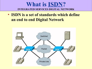
1. What is ISDN?
INTEGRATED SERVICES DIGITAL NETWORK
• ISDN is a set of standards which define
an end to end Digital Network
2. Features of ISDN
• Uses Digital Signal
• Uses Existing telephone wiring
• Charges are generally based on the duration of
call (How long the WAN link was used)
• Alternate to using leased lines
• Can transport many types of Network traffic
(Voice, Data, Video, Text, Graphics etc)
• Faster Data transfer rate than modems
• Faster Call setup than Modems
4. ISDN Components
• Terminal Equipment type 1 (TE1)
A TE is any piece of communicating equipment that
complies with the ISDN standards. Examples include:
digital telephones, ISDN data terminals, Group IV Fax
machines, and ISDN-equipped computers.
• Terminal Equipment type 2 (TE2)
* ISDN Non-compatible devices.
* Will require a terminal adapter.
• Terminal Adapter (TA)
* Converts standard electrical signals into the form used by ISDN
* Needed for connection with TE2 devices
* The ISDN TA can be either a standalone device or a board inside the
TE2
5. ISDN Components
Terminal Adapter (TA)
•Converts standard electrical signals into the form used
by ISDN
Network Termination (NT1 and NT2)
The NT devices, NT1 and NT2, form the physical and logical
boundary between the customer's premises and the carrier's network.
NT1 performs the logical interface functions of switching and local-
device control (local signalling).
NT2 performs the physical interface conversion between the
dissimilar customer and network sides of the interface.
6. ISDN Components
• Exchange Termination (ET)
The ET forms the physical and logical boundary between the digital
local loop and the carrier's switching office.
It performs the same functions at the end office that the NT performs
at the customer's premises.
7. ISDN Reference points
Reference points are a series of specifications that
define the connection between specific devices,
depending on their function in the end-to-end
connection
8. ISDN Reference points
The ISDN standards specify four distinct interfaces in the customer's
connection to the network: R, S, T, and U.
The R Interface
The interface at reference point R is the physical and logical
interface between a non-ISDN terminal device and a terminal adapter
(TA).
The S Interface
The interface at reference point S is the physical and logical interface
between a TE (or TA) and an NT.
The T Interface
The interface at reference point T is the physical and logical interface
between NT1 and NT2, whenever the two NTs are implemented as
separate pieces of hardware.
9. ISDN Reference points
The U Interface
The interface at reference point U is the physical and logical
interface between NT (or NT2) and the ISDN carrier's local
transmission loop.
11. ISDN Service
PRI (Primary Rate Interface)
• ISDN Primary Rate Interface service provides digital access via a T1
line. A T1 line provides a 1.544 bandwidth. This bandwidth is divided
into 24 64Kb channels. The ISDN PRI service uses 23 B channel
access and uses the 24th (D) channel for signaling purposes
12. ISDN Protocols
Protocols which start with the following letter:
• E - Protocols recommend telephone network standards for
ISDN
• I - Protocols for Concepts, terminology and general methods
• Q - Protocols, how switching and signaling should operate,
call setup etc.
13. Dial on Demand Routing
• ISDN LAN routers provide routing between ISDN BRI and the LAN
by using dial-on-demand routing (DDR)
• DDR automatically establishes and releases circuit-switched calls,
providing transparent connectivity to remote sites based on
networking traffic
• DDR also controls establishment and release of secondary B channels
based on load thresholds
15. Cellular Radio Networks
A cellular network is a radio network distributed over
land areas called cells, each served by at least one fixed-
location transceiver known as a cell site or base station.
When joined together these cells provide radio coverage
over a wide geographic area. This enables a large number
of portable transceivers (e.g., mobile phones, pagers, etc.)
to communicate with each other and with fixed transceivers
and telephones anywhere in the network, via base stations,
even if some of the transceivers are moving through more
than one cell during transmission.
16. Advantages
Cellular networks offer a number of advantages over alternative
solutions:
1) Increased capacity
2) Reduced power use
3) Larger coverage area
4) Reduced interference from other signals
18. The Concept
Why Called Cellular Network?
In a cellular radio system, a land area to be supplied with radio service
is divided into regular shaped cells, which can be hexagonal, square,
circular or some other irregular shapes, although hexagonal cells are
conventional.
Each of these cells is assigned multiple frequencies (f1 - f6) which have
corresponding radio base stations.
19. The Concept
What is Frequency Reusing?
In a cellular radio system, the group of frequencies can be reused in
other cells, provided that the same frequencies are not reused in
adjacent neighboring cells.
The elements that determine frequency reuse are the reuse distance and
the reuse factor.
The reuse distance, D is calculated as
where R is the cell radius and N is the number of cells per cluster. Cells
may vary in radius in the ranges (1 km to 30 km)
20. Directional antennas
A cellular map can be redrawn with the
cellular telephone towers located at the
corners of the hexagons where three
cells converge. Each tower has three
sets of directional antennas aimed in
three different directions with 120
degrees for each cell (totaling 360
degrees) and receiving/transmitting
into three different cells at different
frequencies. This provides a minimum
of three channels (from three towers)
for each cell.
21. Handoff
In a cellular system, as the distributed mobile transceivers move from
cell to cell during an ongoing continuous communication, switching
from one cell frequency to a different cell frequency is done
electronically without interruption and without a base station operator or
manual switching.
This is called the handover or handoff. Typically, a new channel is
automatically selected for the mobile unit on the new base station which
will serve it.
The mobile unit then automatically switches from the current channel to
the new channel and communication continues.
22. Example of a cellular radio network
The most common example of a cellular radio network is a mobile phone
(cell phone) network.
A mobile phone is a portable telephone which receives or makes calls
through a cell site (base station), or transmitting tower. Radio waves are
used to transfer signals to and from the cell phone.
There are a number of different digital cellular technologies, including:
1) Global System for Mobile Communications (GSM), 2) Code Division
Multiple Access (CDMA), 3) Evolution-Data Optimized (EV-DO), 4)
Digital Enhanced Cordless Telecommunications (DECT), 5) Digital
AMPS (IS-136/TDMA), 6)Integrated Digital Enhanced Network
(iDEN).
23. Intelligent network
The Intelligent Network, typically stated as its acronym IN, is a
network architecture intended both for fixed as well as mobile
telecom networks.
It allows operators to differentiate themselves by providing value-
added services in addition to the standard telecom services such as
PSTN, ISDN and GSM services on mobile phones.
24. Examples of IN services
1) Televoting
2) Call screening
3) Telephone number portability
4) Toll free calls / Freephone
5) Prepaid calling
6) Account card calling
7) Virtual private networks (e.g. : Family group calling)
8) Private-number plans
9) Mass-calling service
10) Prefix free dialing
11) Call Queueing
12) Call transfer
25. History and key concepts
The major driver behind the development of the IN system was the need
for a more flexible way of adding sophisticated services to the existing
network.
Before IN was developed, all new feature and/or services that were to be
added had to be implemented directly in the core switch systems.
This made for very long release cycles as the bug hunting and testing
had to be extensive and thorough to prevent the network from
failing.
26. Main Concepts - SS7 Architecture
Service Switching Function (SSF) or Service Switching Point (SSP)
This is co-located with the telephone exchange itself, and acts as the
trigger point for further services to be invoked during a call.
Service Control Function (SCF) or Service Control Point (SCP) This
is a separate set of platforms that receive queries from the SSP. The SCP
contains service logic which implements the behaviour desired by the
operator, i.e., the services.
Service Data Function (SDF) or Service Data Point (SDP) This is a
database that contains additional subscriber data, or other data required
to process a call.
27. Main Concepts - SS7 Architecture
Service Management Function (SMF) or Service Management Point
(SMP) This is a platform or cluster of platforms that operators use to
monitor and manage the IN services.
Service Creation Environment (SCE) This is the development
environment used to create the services present on the SCP. Although
the standards permit any type of environment, it is fairly rare to see low
level languages like C used.
Specialized Resource Function (SRF) or Intelligent Peripheral (IP)
This is a node which can connect to both the SSP and the SCP and
delivers additional special resources into the call, mostly related to voice
data
29. Benefits of SS7
• Major benefits include
– improves the speed and flexibility of call setup
– allows processors to exchange information
rapidly for a call requiring special routing or
handling
– enables operation companies to access customer
information stored in network databases to
deliver advanced telecommunications services
network wide
30. Intelligent Network - Summary
• Intelligent Network, IN offers
– Open standards, vendor independence
– Rapid service creation and deployment
– Total network and customer management
– Customized services to users
– New opportunities to make business ie. new
markets and customers
– Rapid adaptation to market needs and
competition
Competitive edge
32. Private network
In the Internet addressing architecture, a private network is a network
that uses private IP address space
Computers not connected to the Internet, such as factory machines that
communicate only with each other via TCP/IP, need not have globally
unique IP addresses.
Three ranges of IPv4 addresses for private networks were reserved in
RFC 1918.
These addresses are not routed on the Internet and thus their use
need not be coordinated with an IP address registry.
33. Private network
These addresses are characterized as private because they are not
globally delegated, meaning they are not allocated to any specific
organization, and IP packets addressed by them cannot be transmitted
onto the public Internet.
Anyone may use these addresses without approval from a regional
Internet registry (RIR).
If such a private network needs to connect to the Internet, it must
use either a network address translator (NAT) gateway, or a proxy
server.
34. Private IPv4 address spaces
The Internet Engineering Task Force (IETF) has directed the Internet
Assigned Numbers Authority (IANA) to reserve the following IPv4
address ranges for private networks, as published in RFC 1918
35. Private IPv6 address spaces
The concept of private networks and special address reservation for such
networks has been carried over to the next generation of the Internet
Protocol, IPv6.
The address block fc00::/7 has been reserved by IANA as described
in RFC 4193. These addresses are called Unique Local Addresses
(ULA). They are defined as being unicast in character and contain a 40-
bit random number in the routing prefix to prevent collisions when two
private networks are interconnected. Despite being inherently local in
usage, the IPv6 address scopes of unique local addresses is global.
36. Common Uses
The most common use of private networks are for residential n/w
purpose, since most Internet service providers (ISPs) only allocate a
single routable IP address to each residential customer, but many homes
have more than one computer or other Internet connected device, such as
televisions.
In this situation, a network address translator (NAT) gateway is usually
used to provide Internet connectivity to multiple hosts.