Good Stuff Happens in 1:1 Meetings: Why you need them and how to do them well
Sabari1
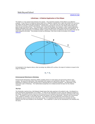
1. Math Beyond School return to top Lithotripsy - A Medical Application of the Ellipse The ellipse is a very special and practical conic section. One important property of the ellipse is its reflective property. If you think of an ellipse as being made from a reflective material then a light ray emitted from one focus will reflect off the ellipse and pass through the second focus. This is also true not only for light rays, but also for other forms of energy, including shockwaves. Shockwaves generated at one focus will reflect off the ellipse and pass through the second focus. This characteristic, unique to the ellipse, has inspired a useful medical application. Medical specialists have used the ellipse to create a device that effectively treats kidney stones and gallstones. A lithotripter uses shockwaves to successfully shatter a painful kidney stone (or gallstone) into tiny pieces that can be easily passed by the body. This process is known as lithotripsy. Click here to see an animation of an ellipse reflection. As illustrated in the diagram above, when as energy ray reflects off a surface, the angle of incidence is equal to the angle of reflection.Extracorporeal Shockwave LithotripsyExtracorporeal Shockwave Lithotripsy (ESWL) enables doctors to treat kidney and gall stones without open surgery. By using this alternative, risks associated with surgery are significantly reduced. There is a smaller possibility of infections and less recovery time is required than for a surgical procedure. The lithotripter is the instrument used in lithotripsy. The mathematical properties of an ellipse provide the basis for this medical invention. The Foci The lithotripter machine has a half ellipsoid shaped piece that rests opening to the patient’s side. An ellipsoid is a three dimensional representation of an ellipse. In order for the lithotripter to work using the reflective property of the ellipse, the patient’s stone must be at one focus point of the ellipsoid and the shockwave generator at the other focus. The patient is laid on the table and moved into position next to the lithotripter. Doctors use a fluoroscopic x-ray system to maintain a visual of the stone. This allows for accurate positioning of the stone as a focus. Because the stone is acting as one of the focus points, it is imperative that the stone be at precisely the right distance from the focus located on the lithotripter. This is essential in order for the shockwaves to be directed onto the stone.The Cushion The lithotripter also contains a coupling device. This is needed for the successful transmission of the rays through the body. A cushion, somewhat like a water balloon, wraps around the half ellipsoid. The cushion is filled with water and rests against the patient’s side. The cushion is sealed to the patient’s body using a silicone membrane. It is the water that allows the shockwaves to travel through the body’s tissues safely because water and the soft tissue have the same density. The stone has a greater density and is shattered by the shockwaves, but the soft tissue suffers only minimal damage. Before the new lithotripters were made, patients would lay in a water bath to create the same effect. Shockwaves Electrohydraulic, piezoelectric, and electromagnetic energy systems use the focus of the ellipsoid to create the shockwaves needed to fracture the stone. The waves are generated at one focus and because of the elliptical shape, the waves are redirected onto the second focus, which is the stone itself. All of these waves cause the stone to crack and it eventually fragments into many tiny pieces that can then be easily passed by the body.Image reproduced with permission of Medispec The process of lithotripsy takes about an hour. The patient can usually return home the same day and is not subjected to a lengthy recovery that is frequently required after surgery. Lithotripsy is virtually painless. The vibration and noise of the shocks can be uncomfortable and so most patients require minimal anesthesia. For these reasons, lithotripsy is becoming a popular treatment for many patients. Most of us reach a point in our projects where we have to make use of gears. Gears can be bought ready-made, they can be milled using a special cutter and for those lucky enough to have access to a gear hobber, hobbed to perfect form. Sometimes though we don't have the money for the milling cutters or gears, or in search of a project for our own edification seek to produce gears without the aid of them. This article will explain how to draw an involute gear using a graphical method in your CAD program that involves very little math, and a few ways of applying it to the manufacture of gears in your workshop. An Application: Milling a gear from flat stock with CNC If we want to mill this gear out of a flat plate on a CNC milling machine we need to figure out what diameter endmill will generate a minimum radius that won't interfere with the gear. If you are lucky enough to have access to a laser or water abrasive jet machine then you don't have to worry about this. We can do this graphically by drawing two meshing gears and either inserting a circle of the diameter of an endmill in the tooth gullet - it should be apparent whether it interferes with the gear teeth (remember that we are concerned with the fillet the endmill produces, not the endmill itself, it can overlap the other gear's tooth), or by inquiring in the cad program to the length of the root arc. In this case a 1/16
endmill will not interfere with the gear teeth meshing. A rule of thumb that seems to work is to use an endmill with a diameter not larger than: DR * Pi / 2T = 1.1054 * PI / 40 = .0868
A 1/16
endmill is .0625
so it should work, I have not tested this rule of thumb for all possible gears so revert to graphical analysis if you have any doubts. The drawing is imported into a CAM program and the g-code generated to mill the gear profile. Picture shows the gear being milledPicture shows the two completed gears meshing with a distance between centers of D (the sum of the pitch radii of the two gears). The gears milled with the method seem almost perfect and mesh perfectly in spite of the small steps that make up the approximate involute. Another Application,
Approximate Hobbing
: In his excellent article on
Spur Gears and Pinions
(HSM April 1999, Vol. 12, #2 pp. 8-15), John A. Cooper outlines a method for forming a gear with a cutting tool that is a circular rack of the same pitch as the gear. Part of his method entails cutting the individual teeth, then lowering the cutter by half the circular pitch (CP) while keeping it engaged with the blank, thus rotating the blank while keeping the teeth in mesh and taking a second series of cuts, generating a good approximation of the involute.