1. 1
TYPES OF SEDIMENTATION TANKS
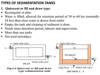
1. Quiescent or fill and draw type:
Rectangular in plan.
Water is filled, allowed for retention period of 30 to 60 hrs (normally
24 hrs) then clear water is drawn from outlet
Empty the tank and cleaning of sediment is done.
Needs more detention period, labours and supervision,
More than one tanks
Not used nowadays.
6. 6
PROCESS OF SEDIMENTATION WITH COAGULATION
1. Feeding the coagulant
Dry feeding
Wet Fedding
2. Mixing of coagulant
a. Mixing basin with baffle walls
b. Mixing basin with mechanical means
c. Mixing channels
d. Hydraulic jump method
e. Compressed air method
f. Centrifugal pumping method
3. Flocculation
4. Sedimentation
14. 14
a. Enclosure tank:
depth = 2.5 – 3.5 m
surface area = 10 – 2000 m2
filtration rate = 100 – 200 lph/m2
cross slope = 1 in 100 – 1 in 200 towards central drain
b. Filter media:
• sand layer = 90 – 110 cm thick
• effective size (D10) = 0.25 – 0.35 mm (0.3 mm is common)
• coefficient of uniformity (Cu) = 3 – 5.
c. Base material:
• 30 to 75 cm thick gravel
• four layers of each about 15 cm
• 3 – 6 mm, 6 – 20 mm, 20 – 40 mm and 40 – 65 mm from the
top
e. Appurtenances: vertical air pipes, depth controlling
devices,head loss measuring device, rate maintaining devices
etc
15. 15
d. Under drainage system:
Efficiency of SSF:
98 – 99% bacteria removal
removes turbidity up to 50 ppm
Only 20 – 25 % of color removal
not so efficient in removal of colloidal matters
17. 17
a. Enclosure tank:
depth = 2.5 – 3.5 m
surface area = 10 – 50 m2
filtration rate = 3000 – 6000 lph/m2
Length width ratio = 1.25 – 1.35
b. Filter media:
sand layer = 60- 90 cm thick
effective size (D10) = 0.35 – 0.60 mm
coefficient of uniformity (Cu) = 1.3-1.7.
c. Base material:
• 45 to 60 cm thick gravel
• four layers of each about 15 cm
• 2 – 6 mm, 6 – 12 mm, 12 – 20 mm and 20 – 50 mm from the
top
19. 19
e. Appurtenances:
Wash water trough, air
compressor, rate
control device, head
loss indicators meters,
valves etc
Efficiency of RSF:
35-40 ppm turbidity removal
removes colour below 3 ppm
Less efficient in iron and manganese removal
not efficient in odour removal
Less efficient in bacteria removal (Only 80 – 90 %)
20. 20
3. Pressure filter (PF)
water is passed under pressure of 3 – 7 kg/cm2 through pumping
Rate of filtration of PF is 6000 – 15000 lit/hr/m2 of filter area
low efficient than RSF for the removal of color, turbidity and bacterial
load
can be used for small colonies, industry and swimming pools etc.
22. 22
DISINFECTION
To kill pathogens
Chemicals called disinfectants
Characteristics of a good disinfectants:
1.Should be able to destroy all harmful bacteria
economically within the contact time and in the wide
range of temperature and pH values.
2.It should not render the water toxic or impart colour and
odour.
3.It should be easily available at reasonable cost.
4.It should be safe to handle and method of application
should be simple.
5.It should persist in residual concentrations as safeguard
recontamination.
23. 23
Methods of disinfection: Chlorination
• When Chlorine is used Cl2 + H2O ↔ HOCl + H+ + Cl –
[Called Hydrolysis reaction occurs at 49 - 212°C]
The HOCl further dissociates (ionizes) as follows
HOCl ↔ H+ + OCl – [Called Ionization reaction]
HOCl and OCl – penetrate cell walls and reacts with the enzyme
system in the cell of micro-organism and results death of micro-
organism
24. 24
FORMS OF APPLICATION OF CHLORINE
(a) Bleaching powder
CaOCl2 ↔ Ca++ + 2 OCl –
H+ + OCl – ↔ HOCl –
this process is called hypochlorination
(b) Chloramines
H2O + Cl2↔ HOCl + H++ Cl –
NH3 + HOCl ↔ NH2Cl (monochloramine) + H2O
NH2Cl + HOCl ↔ NHCl2 (dichloramine) + H2O
NHCl2 + HOCl ↔ NCl3 (trichloramine) + H2O
(c) Chlorine gas or liquid chlorine
(d) Chlorinedioxide
2NaClO2 + Cl2 ↔ 2NaCl + 2 ClO2↑
25. 25
CHLORINE DEMAND AND DOSE
(a) Chlorine demand
Chlorine demand = Total amount of chlorine added – Amount of
residual chlorine required after a specified contact period
Reaction for combined available chlorine:
Cl2 + H2O ↔ HOCl + H++ Cl –
NH3 + HOCl ↔ NH2Cl (monochloramine) + H2O
NH2Cl + HOCl ↔ NHCl2 (dichloramine) + H2O
NHCl2 + HOCl ↔ NCl3 (trichloramine) + H2O
(b) Chlorine dose
Quantity of chlorine required to be added to water to leave 0.2 mg/l
or ppm of freely available residual chlorine after 10 minutes of
contact period
26. 26
FORMS OF CHLORINATION
1. Plain chlorination or simple chlorination:
To raw water
2. Pre-chlorination:
Before treatment
3. Post chlorination:
After treatment
4. Double or multiple chlorination:
Two or more point
5. Super chlorination:
Application beyond break point
6. De-chlorination
Removing chlorine
7. Break point chlorination or free residual chlorination:
28. 28
FACTORS AFFECTING BACTERIAL EFFICIENCY OF
CHLORINE
1.Turbidity: low efficient
2.Presence of metallic compound: Efficiency is
decreased.
3.Ammonia compound: Efficiency is decreased
4.pH value of water: If pH is high in water, efficiency is
low
5. Temperature: If temperature decreased, efficiency
decreased.
6.Time of contact: time of contact should be at least 30
minutes.
7.Type, condition and concentration of micro-organism:
Efficiency low if the favorable condition for bacteria is
available and concentration of bacteria is high.
29. 29
WATER SOFTENING
• Process of removing hardness
• Purpose: To remove Hardness
A. Removal of temporary hardness:
(a) Boiling:
It is costlier and not used in public water supply.
Ca(HCO3)2 CaCO3↓ + CO2↑ + H2O
Mg(HCO3)2 MgCO3↓ + CO2 ↑+ H2O
(b) Adding lime:
Ca(HCO3)2 + Ca(OH)2 → 2CaCO3↓ + 2H2O
Mg(HCO3)2 + Ca(OH)2 → CaCO3↓ + MgCO3↓ + 2H2O
32. 32
C. Demineralization or deionization process:
Regeneration of zeolite:
22 Cl
Mg
Ca
ZNa2NaClZ
Mg
Ca
+→+
+
+
→
+
2HCl
SOH
2COO2H
R
Mg
Ca
Cl
SO
)(HCO
Mg
Ca
RH 42
22
2
4
23
2
Regeneration of hydrogen exchanger:
+→+
2
4
2
42
2
Cl/Cl
SO
2Na
Mg
Ca
RH
HCl
SOH
R
Na
Mg
Ca
33. 33
MISCELLANEOUS TREATMENT
A. Aeration:
(A) Aeration
(B) Removal of iron and manganese
(C) Removal of colour odour and taste
Purpose of aeration:
1. To make water fresh by absorbing oxygen from air.
2. To release dissolved gases (CO2, H2S etc) to
atmosphere.
3. To remove bad taste and odour.
4. To reduce corrosiveness of water.
5. To precipitate Fe and Mn to some extent by oxidizing.
6. To kill harmful bacteria to some extent.
7. To mix mixing chemicals to water.
41. 41
B. Removal of iron and manganese:
Effect:
i. Produce taste, odour and brown red colour.
ii.Stains on clothes, corrosion and clogging of pipes by
accumulation of precipates.
iii.Causes difficult in various industrial process.
Purpose: Removal of iron and manganese
Methods:
(a) By aeration
(b) By adding lime
(c) Passing over manganese zeolite
42. 42
(a) By aeration: In this case aeration is done before
sedimentation.
Fe:
4Fe + O2 + 10 H2O → 4Fe(OH)3 ↓ + 8H
Fe(HCO3)2 :
Fe(HCO3)2 + 2H2O → FeO + 2CO2 + 3H2O
4FeO + O2 → 2Fe2O3
Fe2O3 + 3H2O → 2Fe(OH)3 ↓
Mn:
6Mn + 3O2 + 6H2O → 6MnO2 ↓ + 12H
43. 43
C. Removal of colour, odour, taste:
Purpose: Removal of colour, odour and taste
Methods:
(a) By aeration
(b) By activated carbon treatment
• Activated carbon is manufactured by heating saw
dust, paper mill waste etc. at 500°C in a closed vessel
in controlled condition of burning at 800°C.
• readily available in market in powder or granular
form
• absorbs organic matters and removes colour, odour
and taste.
(c) Using copper sulphate: in swimming pools
44. SODIS method is very easy to
apply: A transparent PET bottle is
cleaned with soap. Then, the bottle
is filled with water and placed in
full sunlight for at least 6 hours.
The water has then been
disinfected and can be drunk.
49. BIO SAND FILTER
• (BSF) is a point-of-use water treatment system adapted
from traditional slow sand filters.
• Bio sand filters remove pathogens and suspended solids
from water using biological and physical processes that take
place in a sand column covered with a bio film.
• BSFs have been shown to remove heavy metals, turbidity,
bacteria, viruses and protozoa.
• BSFs also reduce discoloration, odor and unpleasant taste.
• Studies have shown a correlation between use of BSFs and
a decrease in occurrence of diarrhea because of their
effectiveness, ease of use, and lack of recurring costs, bio
sand filters are often considered appropriate technology in
developing countries.
50.
51.
52.
53.
54.
55. How Well Does the Bio sand Filter Work?
• Water naturally contains many living things. Some are harmless and
others can make people sick. Living things that cause disease are also
known as pathogens. They are sometimes called other names, such
as microorganisms, microbes or bugs, depending on the local
language and country.
• There are four different categories of pathogens that are : bacteria,
viruses, protozoa and helminths.
• Turbid water looks cloudy, dirty or muddy and is caused by sand, silt
and clay that are floating in the water. Drinking turbid water will not
make people sick by itself.
• However, viruses, parasites and some bacteria can sometimes attach
themselves to the suspended solids in water.
• This means that turbid water usually has more pathogens so drinking
it increases the chances of becoming sick
56. 56
CHAPTER 7: INTRODUCTION TO CONVEYANCE
• Transportation of water to treatment plant or reservoir or
distribution through conduits.
• Transmission: Source – TP – Reservoir
• Distribution: Reservoir – Users Tap
• Conduits:
A. Gravity: Open channel flow
Canals, aqueducts, tunnels
B. Pressure
Pipes, pressure tunnels, pressure aqueducts etc.
57. 57
PIPE, PIPE MATERIALS AND PIPE TYPES
Pipe:
• Circular conduit where fluid flows under pressure
• Designed to carry external and internal loads
Requirement of good pipe:
• Withstand external, internal and temperature stresses
• Smooth for minimum frictional losses
• Durable
• Light
• Noncorrosive
• Cheap
• Easy joint
59. 59
(a) Cast Iron (CI) Pipe:
• Manufactured by sand molding or centrifugal method
• Standard 1.8 m length but up to 3m for smaller diameter
• 50 mm to 1.2 m dia.
Advantages:
Easy to join, can withstand high pressure, resistance to
corrosion, long life (> 100 yrs), durable, strong and moderate
in cost, joined by flanged or Spigot and socket joint, low
maintenance cost.
Disadvantages:
Brittle and very heavy so difficult to transport and may be
expensive.
Suitability: Suitable for distribution system.
60. 60
(b) Wrought Iron (WI) Pipe:
• Manufactured by rolling the flat plates of metal to
proper diameter and welding to the edges
Advantages:
Strong, light weight, can withstand high pressure (400
m) and cheaper than CI pipes
Disadvantages:
It can’t withstand external load and when there is no
water inside, liable to corrosion and costly to maintain.
It is costlier than CI pipes
Suitability: Occasionally used for main lines where
pressure is high
61. 61
(c) Steel Pipe:
• Manufactured by WI or mild steel which are galvanized by
providing a protective coating of zinc on inner and outer surface
Advantages:
It is cheap, light, easy in handling and transport, easy in joining with
screwed socket joints and 20 years of life, resistant to corrosion
when exposed to atmosphere
Disadvantages:
may get corroded by acidic and alkaline waters and liable to
incrustation.
Suitability: main lines where pressure is high and when pipe is
exposure in open atmosphere
62. 62
(d) Galvanized iron (GI) pipes:
• Manufactured similar as WI pipes
• 15,20,25,32,40,50,63,75,90,110,125,150, 200 mm inner dia
Advantages:
Light in weight, easy in transport, handling, cutting, threading,
working, joining, and gives neat appearance, joined couplings or
screwed socket joint.
Disadvantages:
Costly, corrosive and less durable than CI pipes
Suitability: Inside plumbing in buildings but not used nowadays due
to high cost.
63. 63
(e) Concrete (GI) pipes:
• Made of cement concrete (precast or cast in site)
Advantages:
Withstand 150 m head of water, resist corrosion and life is above
75 years, maintenance cost is low, least thermal expansion, can be
laid under water and resist normal traffic load
Disadvantages:
Precast type is heavy to handle and transport, concrete pipes can’t
resist high pressure and difficult to repair, it may be affected by
acids and alkali and salty waters, difficult to join and liable to leak
due to porosity
Suitability:
Where water does not flow under pressure (i.e. sewerage system)
64. 64
(f) Asbestos cement (AC) pipes:
• Made of mixture of cement and asbestos fibers
Advantages:
not affected by salt water and corrosive materials, smooth,
light so easy in handling
Disadvantages:
Affected by alkali and acid and also brittle so costlier in
transport.
Suitability:
Small size distribution pipes
65. 65
(g) Wooden pipes:
• made of wood by making channels or boring at center and used
in ancient times
• not used in water supply nowadays
(h) Vitrified clay Pipes:
• made of vitrified clay so has smooth surface
• not used in water supply nowadays
(i) Lead and copper Pipes:
• Copper pipe is made of copper and can resist corrosion even if
water contains some acids and expensive so not used in water
supply nowadays
• Leads are soluble in water so lead pipe causes lead poisoning
hence it is not used in water supply nowadays.
66. 66
(f) Plastic Pipes:
• Made of Plastic and common in nowadays
• it is corrosion resistant, light in weight and economical
Advantages:
Light, cheap, available in longer length, electrical insulation,
corrosion free, life correspond to GI
Disadvantages:
Less resistant to hot water, may impart smell to water, can be easily
cut.
Suitability:
All water sypply systems
67. 67
Types:
1. Low density polyethylene (LDPE) pipes:
Used in electrical wiring
2. High density polyethylene (HDPE)pipes
3. Polyvinyl chloride (PVC) pipes:
4. Unplastisized Polyvinyl chloride (UPVC) pipes:
5. Poly Propylene Random (PPR) Pipes:
Plastic Pipes
68. 68
LAYING OF PIPES
1.Preparation of detailed maps:
2.Locating proposed alignment of pipeline on the
ground:
3.Location of pipes with respect to ground surface
during laying
4.Excavation of trench:
5.Dewatering of trench:
6.Lowering the Pipes:
7.Joining pipes:
8.Testing of pipes:
9.Back filling and disinfection before first use:
75. 75
CHAPTER 8: VALVES AND FITTINGS
(a) Sluice or gate or cutoff valve
(b) Reflux or check or non-return valve
(c) Safety or pressure relief valve
(d) Air valve or air relief valve
(e) Drain or scour or blow off valve : Ordinary sluice valve to
remove silt deposit
(f) Butterfly valve and globe valve
Devices used to control the flow of water, regulate pressures,
release air, prevent back flow etc
79. 79
FIRE HYDRANT:
Devices used for tapping water from mains for the
fire extinguishing, street washing, watering gardens,
flushing sewer lines etc.
Provided at all road junctions & every 100 – 300 m
apart.
For tapping water, the hose is connected to the
hydrant and if necessary the engine is used to
increase head.
It should be cheap, easily connectable & detachable
to the hose pipe and able to give sufficient water. It
may be of post type or flush type.
84. 84
CHAPTER 9: PLANNING OF GRAVITY WATER SUPPLY
• Need identification of scheme
• After need identification, mass meeting is called, prioritize is
done and then scheme acquisition form is filled up and submitted
to VDC, DDC and divisional district water supply office
• With feasibility study report the schemes are forwarded from
divisional office thru regional office to department of water
supply and sewerage (DWSS)
• After obtaining scheme acquisition form list from all 75 districts
, budget ceiling is prepared for forthcoming fiscal year by DWSS
and forward to ministry of concern.
• The ministry approves ceiling consulting with National planning
commission then distributed to DWSS and district offices for
implementation
85. 85
• After obtaining approved budget ceiling, detailed survey
is carried out.
• Detail survey
horizontal and vertical control and
questionnaire
• Analysis based on detail survey, the design, drawing,
estimating and costing is done and final report is
prepared.
• Water Users Committee (WUS) is formed and trained in
agreement with WUC or implementation agency
• After agreement, construction is carried out and it is
handover to the WUC.
• WUC are responsible for regular maintenance.