Organizational Structure Running A Successful Business
E nodeb
1. Application Note
LTE eNodeB Installation and Maintenance Tests
Introduction
The Long-Term Evolution (LTE) specifications are defined by the Third Generation Partnership Project
(3GPP), which is part of the Standards Development Organizations.
LTE Characteristics:
Improved downlink and uplink peak rates:
UE Category
Maximum
Spatial Downlink
Maximum
Uplink
Downlink Data
Multiplexing
Uplink Data
64QAM
(Mbps) (Mbps)
Category 1
Category 2
Category 3
Category 4
Category 5
10.296
51.024
102.048
150.752
299.552
1
2
2
2
4
5.160
25.456
51.024
51.024
75.376
No
No
No
No
Yes
Scalable channel bandwidths:
Channel bandwidth (MHz)
Transmission bandwidth (RB)
Transmission bandwidth (Subcarriers)
Transmission bandwidth (MHz)
1.4
6
72
1.08
3
15
180
2.7
5
25
300
4.5
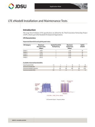
LTE Downlink Signal – Frequency Mode
LTE Downlink Signal – Frequency Mode
WEBSITE: www.jdsu.com/test
10
50
600
9
15
75
900
13.5
20
100
1,200
18
2. Application Note: LTE eNodeB Installation and Maintenance Tests
2
Operating Bands and Channel Numbering
The carrier frequency in the uplink and downlink is designated in the range of 0 − 65535. The relation between
channel numbering and carrier center frequency in MHz for the downlink is given by the following equation,
where FDL_low and NOffs-DL are given by 3GPP.
Downlink Center Frequency (FDL) = FDL_low + 0.1(NDL – NOffs-DL)
Channel Number (NDL) = (FDL – FDL_low)/0.1 + NOffs-DL
For example, the center frequency of channel number (NDL) 5230 on band 13 is the following:
746 + 0.1(5230 – 5180) = 751 MHz
3. Application Note: LTE eNodeB Installation and Maintenance Tests
3
Downlink Signal Format
LTE downlink signal is based on the technique of orthogonal frequency division multiplexing (OFDM), where
different streams of information are mapped onto separate parallel frequency channels and each channel is
separated from the others by a frequency guard band to reduce interference between adjacent channels.
Data symbols are synchronously and independently transmitted over a high number of closely spaced
orthogonal subcarriers using linear modulation, either phase shift keying (PSK) or quadrature amplitude
modulation (QAM).
Orthogonal elements are created between subcarriers (Sc) and consecutive symbols (Sy):
LTE Downlink Signal—Frequency and Time
LTE Signal Description—Frequency and Time
4. Application Note: LTE eNodeB Installation and Maintenance Tests
4
LTE Frame Structure
LTE frame structure type 1 (FDD mode) consists of 20 slots, and a subframe is defined as two consecutive slots.
LTE Frame Structure (FDD)
Physical Downlink Channels
Modulation Schemes
5. Application Note: LTE eNodeB Installation and Maintenance Tests
5
LTE eNodeB Installation and Maintenance Tests
The LTE base station (eNodeB) conformance tests are classified based on its radio frequency (RF)
characteristics, or modulation characteristics. Some of these tests are based on 3GPP TS 36.104, which defines
minimum requirements for LTE base stations eNodeB.
LTE Installation and Maintenance Tests
6. Application Note: LTE eNodeB Installation and Maintenance Tests
6
eNodeB Transmission Test
Test Connectivity
All the commissioning tests should be performed in each port of the corresponding eNodeB for a three-sector
cell site with two TX antennas (TX1 and TX2) for a total of six tests.
Alcatel Lucent with JD740
Alcatel-Lucent eNodeB TX1—JD740
Alcatel-Lucent eNodeB TX2—JD740
7. Application Note: LTE eNodeB Installation and Maintenance Tests
Ericsson with JD740
Ericsson eNodeB TX1 – JD740
Ericsson eNodeB TX2—JD740
7
8. Application Note: LTE eNodeB Installation and Maintenance Tests
8
Test Configuration
The following procedure configures the instrument to properly test the transmitted LTE signals
directly connected into eNodeB. For the external offset, consider the actual offset of the port plus the
test cable loss. The following example considers a 40 dB loss for simplicity. The procedure uses LTE
Band 13 channel 5230 (751 MHz) but the same process applies to any other channel assignment.
JD740 Procedure for eNodeB Test
LTE Signal Analysis Mode for eNodeB Transmission
Frequency Setting for eNodeB Transmission
Amplitude and Power Offset Setting for eNodeB Transmission
9. Application Note: LTE eNodeB Installation and Maintenance Tests
9
Result for eNodeB Test
Saving Results
Follow this procedure to save results on a USB memory device connected into the USB Host port of the base
station analyzer.
JD740 Procedure for Saving Results
10. Application Note: LTE eNodeB Installation and Maintenance Tests
10
Channel Power Test
Definition of Channel Power
The output power of the base station is the mean power of one carrier delivered to a load with resistance equal
to the nominal load impedance of the transmitter.
Maximum output power of the base station is the mean power level per carrier measured at the antenna
connector during the transmitter ON period in a specified reference condition.
Requirements for Channel Power
Under normal conditions, the base station maximum output power shall remain within +2 dB and −2 dB of the
rated output power declared by the manufacturer.
In extreme conditions, the base station maximum output power shall remain within +2.5 dB and −2.5 dB of the
rated output power declared by the eNodeB manufacturer.
JD740 Procedure for Channel Power
Results for Channel Power
Note: In the screen shot for Channel Power Results, the Channel Power is 32.38 dBm, but it may be higher. A ±2 dB
value should be prescribed for the operating mode of the eNodeB.
11. Application Note: LTE eNodeB Installation and Maintenance Tests
11
Occupied Bandwidth Test
Definition of Occupied Bandwidth
The occupied bandwidth is the width of a frequency band where the mean powers emitted below the lower
and above the upper frequency limits are each equal to a specified percentage B/2 of the total mean transmitted
power.
Requirements for Occupied Bandwidth
The specified percentage B/2 must be taken as 0.5 percent.
JD740 Procedure for Occupied Bandwidth
Results for Occupied Bandwidth
12. Application Note: LTE eNodeB Installation and Maintenance Tests
12
Spectrum Emission Mask Test
Definition of Spectrum Emission Mask
The unwanted emission limits of the operating band are defined as 10 MHz below the lowest frequency of the
downlink operating band up to 10 MHz above its highest frequency. The requirements apply regardless of the
type of transmitter used, single carrier or multi-carrier.
Requirements for Spectrum Emission Mask
Emissions must not exceed the maximum levels specified in 3GPP TS 36.104 Subsection 6.6.3.
JD740 Procedure for Spectrum Emission Mask
Results for Spectrum Emission Mask
13. Application Note: LTE eNodeB Installation and Maintenance Tests
13
Adjacent Channel Leakage Power Ratio Test
Definition of Adjacent Channel Leakage Power Ratio
Adjacent channel leakage power ratio (ACLR) is the ratio of the filtered mean power centered on the assigned
channel frequency to that centered on an adjacent channel frequency. The requirements apply regardless of the
type of transmitter used, single carrier or multi-carrier.
Requirements for Adjacent Channel Leakage Power Ratio
For 10 MHz channel bandwidth, the ACLR limit is 45 dB at 10- and 20-MHz offsets.
JD740 Procedure for Adjacent Channel Leakage Power Ratio
Results for Adjacent Channel Leakage Power Ratio
14. Application Note: LTE eNodeB Installation and Maintenance Tests
14
Spurious Emissions Test
Definition of Spurious Emissions
The transmitter spurious emission limits apply from 100 kHz to 7.2 GHz, excluding the frequency range from
10 MHz below the lowest frequency of the downlink operating band up to 10 MHz above its highest frequency.
Requirements for Spurious Emissions
Emissions must not exceed the maximum levels specified in 3GPP TS 36.104 Subsection 6.6.4.
JD740 Procedure for Spurious Emissions
Results for Spurious Emissions
15. Application Note: LTE eNodeB Installation and Maintenance Tests
15
Control Channels Test
Definition of Control Channels
The Control Channel measurement provides the modulation quality of each control channel (for example,
P-SCH, S-SCH, PBCH, PCFICH, PHICH, PDCCH, RS), including the error vector magnitude (EVM)
expressed in percentage, the power (dB or dBm), the modulation type, and the corresponding constellation
diagram (I-Q).
Requirements for Control Channels
The acceptable modulation quality is defined by network performance.
JD740 Procedure for Control Channels
Note: The TX2 test requires changing the antenna port setting. Enter the Cell ID registered on TX1 test if the eNodeB is not transmitting P-SCH
and S-SCH signals.
Results for Control Channels
16. Application Note: LTE eNodeB Installation and Maintenance Tests
16
Data Channels Test
Definition of Data Channels
Data channel measurement provides a resource block granularity into one subframe and is applicable for Base
Station Conformance Testing described in 3GPP TS 36.141: 6.1.1
Requirements for Data Channels
EVM Requirements
The acceptable modulation quality (or error vector magnitude, EVM) for data channels per resource block are
user-configurable by assigning EVM limits to each data channel (for example, QPSK, 16QAM, and 64QAM).
PRB Requirements
The acceptable requirements for active Physical Resource Blocks (PRB) are defined as test models on 3GPP TS
36.141: 6.1.1.
JD740 Procedure for Data Channels
Results for Data Channels
PRB Test Model 1.2
17. Application Note: LTE eNodeB Installation and Maintenance Tests
17
Frames Test
Definition of Frames
The frame measurement provides the EVM expressed in percentage, power (dB or dBm) and modulation type
of each control channel, such as P-SCH, S-SCH, PBCH, PCFICH, PHICH, PDCCH, RS, and data channel,
such as PDSCH-QPSK, PDSCH-16QAM, PDSCH-64QAM, on a complete LTE frame.
Requirements for Frames
For all bandwidths, the EVM measurement must be performed over all allocated resource blocks and
subframes within a frame. The EVM for different modulation schemes on PDSCH must be lower than
these limits:
• PDSCH-QPSK: 17.5 percent
• PDSCH-16QAM: 12.5 percent
• PDSCH-64QAM: 8 percent
JD740 Procedure for Frames
Results for Frames
Note: Register the Cell ID value that is auto-discovered; manual entry may be required for TX2 testing if the
eNodeB does not transmit P-SCH and S-SCH on TX2.
18. Application Note: LTE eNodeB Installation and Maintenance Tests
18
Subframe Test
Definition of Subframes
The subframe measurement provides the EVM expressed in percentage, the power (dB or dBm) and
modulation quality of each control channel, such as P-SCH, S-SCH, PBCH, PCFICH, PHICH, PDCCH, RS,
and data channels, such as PDSCH-QPSK, PDSCH-16QAM, PDSCH-64QAM, on an LTE subframe.
Requirements for Subframes
The modulated carrier frequency of the Base Station must be accurate to within ±0.05 ppm observed over a
period of one subframe (1 ms).
JD740 Procedure for Subframes
Results for Subframes
Note: Performing transmission tests are required for TX1 and TX2 ports on each sector (Alpha, Beta, and Gamma).
Addendum 1 provides a Generic eNodeB Commissioning Test Check List.
19. Application Note: LTE eNodeB Installation and Maintenance Tests
19
eNodeB MIMO Test
eNodeB MIMO Time Alignment
Definition of MIMO Time Alignment
LTE has adopted a multiple antenna mechanism for increasing coverage and capacity. Adding multiple
antennas improves performance because the signals take different paths to achieve diversity and spatial
multiplexing.
Signals can be transmitted from two or more antennas commonly referred to as multiple-input multipleoutput (MIMO). The differentiation of these multiple signals resides on the location of reference signals on the
LTE frame; for example, the reference signals on the first subcarrier of antenna 0 (R0) are in symbols 1 and 8,
whereas for antenna 1 (R1) they are in symbols 5 and 12.
The reference signals from multiple antennas, such as R0 and R1, must be aligned as 3GPP specifies as the delay
between the signals from two antennas at the antenna ports.
Requirements for MIMO Time Alignment Test
The time alignment error in TX diversity or spatial multiplexing for any possible configuration of two
transmission antennas must not exceed 65 ns.
Test Connectivity
Alcatel-Lucent eNodeB TX1 and TX2—JD740
Ericsson eNodeB RXA OUT—JD740
20. Application Note: LTE eNodeB Installation and Maintenance Tests
JD740 Procedure for eNodeB Test
LTE Signal Analysis Mode for eNodeB Transmission
Frequency Setting for eNodeB Transmission
Amplitude and Power Offset Setting for eNodeB Transmission
20
21. Application Note: LTE eNodeB Installation and Maintenance Tests
MIMO Time Alignment Test Setting
Result for eNodeB MIMO Time Alignment Error Test
21
22. Application Note: LTE eNodeB Installation and Maintenance Tests
22
eNodeB Over-the-Air Analysis
Over-the-Air analysis covers the following tests while receiving the signal over the air through an
omnidirectional antenna attached to the RF-in port of the instrument.
• ID Scanner test
• Multipath profile
• Control channel
• Datagram
Test Configuration
Configure the JD740 to perform Over-the-Air analysis as shown below.
23. Application Note: LTE eNodeB Installation and Maintenance Tests
Result of Test Configuration
23
24. Application Note: LTE eNodeB Installation and Maintenance Tests
24
ID Scanner Test
Definition of ID Scanner Test
LTE mobiles must receive signals on the same channel from multiple cell sites at the edge of each cell to ensure
seamless handovers between cells, making it critical to characterize the signal dominance of adjacent cell sites
measuring the primary and secondary sync channels.
The ID Scanner identifies the six strongest cell sites indicating their corresponding physical cell identity in
terms of Cell ID, Group ID, and Sector ID. It measures dominance and power of the primary and secondary
sync channels (P-SCH and S-SCH) for each cell site.
JD740 Procedure for ID Scanner Test
Result of ID Scanner Test
25. Application Note: LTE eNodeB Installation and Maintenance Tests
25
Multipath Profile Test
Definition of Multipath Profile Test
LTE mobiles receive signals from multiple paths from the cell site and directly from the cell site if no
obstructions or reflections of the signal occur from large objects such as water, mountains, or buildings.
The effects of multipath include interference and phase shifting of the signal that might cause errors and affect
quality of service (QoS).
The signal structure of LTE is based on OFDM that minimizes the negative effects of multipath; however, LTE
also uses high modulation schemes, such as 64QAM, that are more sensitive to modulation errors due to the
amount of data transmitted.
Multipath propagation in OFDM can remove one or more subcarriers and, in extreme cases, even loss of signal
acquisition is possible; therefore, it is critical to characterize the multipath profile, particularly in areas that
demonstrate poor performance.
JD740 Procedure for Multipath Profile Test
Result of Multipath Profile Test
26. Application Note: LTE eNodeB Installation and Maintenance Tests
26
Control Channel Test
Definition of Control Channel Test
The control channel test completely characterizes all of the control channels in terms of absolute and relative
power as well as modulation quality (EVM). In addition, it measures MIMO for power and time alignment
of the reference signals received from both antennas at the cell site, TX-Antenna 0 (RS0) and TX-Antenna 1
(RS1). This characterization comprehensively assesses signal strength, quality, and diversity at any location.
JD740 Procedure for Control Channel Test
Result of Control Channel Test
27. Application Note: LTE eNodeB Installation and Maintenance Tests
27
Datagram Test
Definition of Datagram Test
The datagram test measures the power variation over time for all the resource blocks contained on the LTE
channel indicating data utilization over time. The datagram indicates traffic demand to prevent channel
saturation and bandwidth performance ensuring the availability of all data channels.
JD740 Procedure for Datagram Test
Result Datagram Test
28. Application Note: LTE eNodeB Installation and Maintenance Tests
eNodeB Reception Test
Test Connectivity
Alcatel-Lucent with JD740
Alcatel-Lucent eNodeB RX1—JD740
Ericsson with JD740
Ericsson eNodeB RXA OUT—JD740
28
29. Application Note: LTE eNodeB Installation and Maintenance Tests
29
eNodeB Reception
Use the following procedure to configure the instrument to properly test the receiving noise floor for LTE
signals on the eNodeB.
JD740 Procedure for Spectrum Analysis Mode
JD740 Configuration to Set the Offset
If the eNodeB RX port is amplified by 25 dB, it requires setting a 25 dB offset, as follows:
JD740 Configuration to Set Resolution Bandwidth
30. Application Note: LTE eNodeB Installation and Maintenance Tests
30
Noise Floor
Definition of Noise Floor
Noise Floor measures the reference sensitivity level as the minimum mean power received that must meet a
throughput requirement for a specified reference measurement channel.
Requirements for Noise Floor
The throughput must be ≥95 percent of the maximum throughput for the reference measurement channel
with a reference sensitivity power level of −101.5 dBm.
JD740 Procedure for Noise Floor
Results for Noise Floor
31. Application Note: LTE eNodeB Installation and Maintenance Tests
Addendum 1: Generic eNodeB Commissioning Check List
Site Name___________________________________________________________________
Site Address__________________________________________________________________
Date________________________________________________________________________
Test
Cell ID
Group ID
Sector ID
Note all 3 for
each TX
Channel Power
__ ≤ x dBm ≤__
Occupied
Bandwidth
Pass/Fail
SEM
Pass/Fail
ACLR
Pass/Fail
P-SCH Power
__ ≤ x dBm ≤__
P-SCH Power
__ ≤ x dBm ≤__
PCFICH Power
__ ≤ x dBm ≤__
PBCH Power
__ ≤ x dBm ≤__
EVM
0 ≤ x %< 5
Frequency
error
Criteria
0 ≤ x ppm < .05
Alpha TX1
Alpha TX2
Beta TX1
Beta TX2
Gamma
Gamma
TX1
TX1
31
32. Application Note: LTE eNodeB Installation and Maintenance Tests
32
Addendum 2: Measurement Limits
Overview
The base station analyzer can be set with different limit levels for RF analysis and modulation analysis; the
variable limits are as follows:
RF Test Limits – Menu Structure
33. Application Note: LTE eNodeB Installation and Maintenance Tests
Modulation Test Limits – Menu Structure (Part 1)
33
34. Application Note: LTE eNodeB Installation and Maintenance Tests
Modulation Test Limits – Menu Structure (Part 2)
34
35. Application Note: LTE eNodeB Installation and Maintenance Tests
Requirements for Setting Modulation Limits
Use the following procedure to configure RF or Modulation limits.
JD740 Procedure for Setting Modulation Limits
Setting RF Test Limits for Channel Power
Enable the test limit
Set high and low limits
35
36. Application Note: LTE eNodeB Installation and Maintenance Tests
Setting RF Test Limits for Occupied Bandwidth
Enable the test limit
Set the low limit
JD740 Procedure for Setting RF Test Limits for Spectrum Emissions Mask, ACLR, and
Spurious Emissions
Select the test parameter and enable the test limit
36
37. Application Note: LTE eNodeB Installation and Maintenance Tests
Setting Modulation Test Limits for Frequency Error
Enable the test limit
Set high and low limits
Setting Modulation Test Limits for EVM RMS and EVM Peak
Select the test parameter and enable the test limit
37
38. Application Note: LTE eNodeB Installation and Maintenance Tests
Set high and low limits
Setting Modulation Test Limits for Time Error
Enable test limit
Set high and low limits
38
39. Application Note: LTE eNodeB Installation and Maintenance Tests
Setting Modulation Test Limits for IQ Origin Offset
Enable test limit
Set high limit
Setting Modulation Test Limits for RS Power
Select the test parameter and enable the test limit
39
40. Application Note: LTE eNodeB Installation and Maintenance Tests
Set absolute (dBm) limits
Set relative (dB) limits to RS power
40
41. Application Note: LTE eNodeB Installation and Maintenance Tests
41
Addendum 3: Auto Measure
Overview
Auto Measure automatically performs a series of tests for RF analysis and Modulation analysis and includes
these parameters:
• RF analysis
− Channel power
− Occupied bandwidth
− ACLR
− SEM
• Modulation analysis
− IQ origin offset
− Time error
− EVM RMS
− EVM peak
− Frequency error
− RS power
− P-SCH power
− S-SCH power
− PBCH power
− PCFICH power
The limit values of each parameter can be configured according to the parameters in Appendix 2.
42. Application Note: LTE eNodeB Installation and Maintenance Tests
Auto Measure Procedure
To change the limit settings
42
43. Application Note: LTE eNodeB Installation and Maintenance Tests
43
Refer to Appendix 2 for testing limit procedures.
Define the name and location of the measurement results
JD740 Procedure for Auto Measure
Define result storage location (Internal or USB) and screen results to be saved (All or Fail)
Run the test
The instrument will perform all of the selected measurements and upon completion will display the Auto
Measure Settings screen.
To view the summary results