Michael Tetteroo and Cees van der Ben - CCS Projects – Presentation at the Global CCS Institute Members’ Meeting: 2011
•
1 like•827 views


Recommended
Recommended
More Related Content
What's hot
What's hot (20)
Similar to Michael Tetteroo and Cees van der Ben - CCS Projects – Presentation at the Global CCS Institute Members’ Meeting: 2011
Similar to Michael Tetteroo and Cees van der Ben - CCS Projects – Presentation at the Global CCS Institute Members’ Meeting: 2011 (20)
More from Global CCS Institute
More from Global CCS Institute (20)
Recently uploaded
Recently uploaded (20)
Michael Tetteroo and Cees van der Ben - CCS Projects – Presentation at the Global CCS Institute Members’ Meeting: 2011
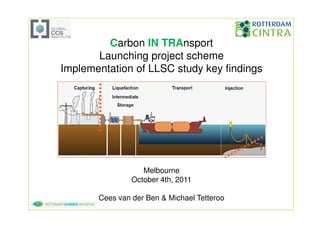
- 1. Carbon IN TRAnsport Launching project scheme Implementation of LLSC study key findings Melbourne October 4th, 2011 Cees van der Ben & Michael Tetteroo
- 2. Note This document and all information contained herein are the property of VOPAK, Anthony Veder, Gasunie & Air Liquide and are Strictly Confidential It may not be copied or used without the written permission of VOPAK, Anthony Veder, Gasunie & Air Liquide 04-10-11 2
- 3. Rotterdam Climate Initiative (RCI) city region CO2 reduction targets -50% vs 1990 by 2025 CCS plays a mayor role in the Dutch national reduction targets in general and in the Rotterdam targets in particular. 04-10-11 3
- 4. NW-Europe allows for short links between sources and sinks Several depleted gas fields become available and in due time incl. future aquifers: 50+ years of storage capacity for Europe. 04-10-11 4
- 5. Driving down costs Sharing infra structure: simultaneously handling CO2 from multiple parties Combining CO2 flows lies in the nature of CCS: Power generation is responsible for 65%* of all green house gas emissions OECD/IEA Ref. Scenario 2006 2030 Majority of sources Total [TWh] 18921 33265 (+76%) are comparable Coal 41% 44% regarding: Nuclear 15% 10% • Flow & conditions Renewables 18% 23% • Compositions • Characteristics • Demands *): Reference Scenario in 2005 & 2030: resp. 61% & 68 % in CO2 eq. terms
- 6. CINTRA logistic concept • Bulk making/breaking for off shore CO2 storage • Intermediate Storage • Combine and link pipeline systems and barging/shipping routes: 4 routes • Provide independent custody transfer metering (for ETS) • Network building block (at rivers and coast lines) • Optimum CO2 : -50 ˚C, 7 bara 04-10-11 6
- 7. CINTRA’s CO2 Hub Partners • Transport from the Emitters via pipelines or barges • Collection of CO2 to the CO2 Hub • Loading of sea vessels / injection in trunk line for transport to depleted offshore gas fields. • Liquefaction at the Emitter’s site or at the CO2 Hub • Temporary Storage of CO2 • Connecting Hub to offshore trunk line or transfer to vessel • Locking the sea vessel to a floating turret or loading tower linked with the sub-sea system of the depleted gas/oil field • Injecting the CO2 into the porous rocks (depleted gas or oil field or aquifers, at required temp’s and pressures • As an alternative, mooring near a platform for discharging the CO2 into a depleted field via the platform utilities 04-10-11 7
- 8. CO2 Hub Concept Advantages • Multiple emitters linked with multiple sinks , increasing reliability of CO2 take-away • Modular design allows easy volume related ramp up • Variable destinations with liquid logistics • Cost reduction through EOR • Reduced project risk without onshore pipelines and onshore storage 04-10-11 8
- 9. How does it work • MOVIE – will be shown during presentation 04-10-11 9
- 10. Hub Concept Organic Growth Model: Asset build up follows the volume build-up Source 1 Source 2 Source 3 Source 4 Source n 3 1 2 2 1. Early scheme: single source flow too 3. Final mature scheme: small to justify off shore pipe multiple sources & sinks, both 2. Intermediate scheme: two combined depleted reservoirs and EOR flows do allow for an off shore pipe at production wells => ship moves into alternative CO2 or LPG service 2 3 3 1 2 Potentially Ship now could ship that become pipe used to sail line for 2 on sink 1 Sink 3: EOR Sink 1 Sink 1 Sink 2 Sink n sources at oil field 04-10-11 10
- 11. Potential CO2 Sinks Other EOR 300 Mton CO2 K12B Projects capacity Taqa 40 Mton CO2 capacity CO2 from other ports • First targeted sink: Dan Field Danish Continental Shelf, EOR Project Maersk Oil • Hub forms a reliable CO2 source for EOR projects, allowing for a stable off take • More contacts with other sink operators at the North Sea • Potential CO2 from other ports will drive down costs for all participants further 04-10-11 11
- 12. Rotterdam distance to sinks • Dutch sinks are all within the 400 km range • Rotterdam Ideally located for North Sea distribution • Offshore EOR potential significant 04-10-11 12
- 13. CO2 Hub Legal/Contractual Framework Providing a One-Stop-Shop Transfer of CO2 title SH SH SH SH Emitter Rotterdam Cintra Sink Operator Necessary sub-contracting Compression Bulk making Sea for other Liquefaction specialized & Transport and terminal Transport services • CO2 title transfers from Emitter to sink Operator • Transport organized via Service Level Agreements 04-10-11 13
- 14. CO2 Hub Legal/Contractual Framework • Emitters as CINTRA’s customers • ETS allowances for Emitter • CINTRA as multi-customer independent operator no title to CO2 • CINTRA Transportation Agreements: long term take- or-pay contracts • TA’s and SLA’s based on repeatable formula • Impartiality and transparency towards customers • CINTRA has one TA per emitter, backed up by one SLA per JV partner each 04-10-11 14
- 15. Stakeholder Management Purpose: mitigate risks associated with negative public perception for CCS Type of Risks: 1. Negative image for companies involved 2. Delay in time 3. Extra costs / investments to be made beyond a first class SHE strategy Steps to come to Stakeholder Strategy: • Step 1: - Actor and network analysis • Step 2: - Inventarization communications and information options • Step 3: - Link actual communication option to key stakeholders • Step 4: - Execution in line with project development 04-10-11 15
- 16. CO2 Hub Location 04-10-11 16
- 17. Connecting Hinterland Barges to CO2 Hub Hub Emitter Emitter • Liquefaction of CO2 at site • River barges transport liquid CO2 over Rhine • Cargoes from several sources can be combined: economies of scale Emitter • Capacity on Rhine is abundant vs. pipeline hardly feasible 04-10-11 17
- 18. Current project status • Launching emitters: – Coal fired power plant + post combustion capture 1.1 MTA – Hydrogen plant 0.4 MTA • Launching sink: Maersk off shore EOR operation • Launching scope: – On shore pipeline: 25 km, 40 bar – Terminal: 2.0 MTA liquefaction capacity, 20 kcbm LCO2 storage – Ships: 2 x 12 kcbm with onboard conditioning equipment – Off loading: double buoy system • Timing: – LOI’s in place: Q4 2011 – FID: Q3 2012 – RFO: Q2 2015 – Challenge: synchronize timing & permitting • Expected 2025 throughput: total 8 MTA of which 15 MTA via barge 04-10-11 18
- 19. Launching Scheme Dan Field on the Danish sector of the North Sea is operated by Maersk Olie og Gas AS on behalf DUC – Dansk Undergrunds Consortium. Dan • 1.5 MTA of CO2 • Rotterdam Denmark • EOR CINTRA 04-10-11 19
- 20. GCCSI LLSC study lessons learned to date General • Start engineering at the sink • Minimize CO2 composition requirements • Combining multiple emitters in one network is technically feasible. • No metallurgical/corrosion issues found other than water => dry the CO2 at the source SHE • No items of concern encountered • Low vessel collision risk due to high LCO2 density • On shore pipeline through busy areas: 40 bar Compression • Up to 100 bar: bull gear compressor ; beyond: pump • Moderate ambient temperatures: no power consumption difference between conventional compression or compression/liquefaction/pumping. Pipeline • In dense phase in order to minimize costs 04-10-11 20
- 21. GCCSI LLSC study lessons learned to date Costs: contract duration Pipeline system tariffs are hurt the most by short term contracts 04-10-11 21
- 22. Transportation Costs: insight evolution LNG CO2 Source: IEA GHG, 2004 CO2 CO2 04-10-11 22
- 23. GCCSI LLSC study lessons learned to date Costs • CO2 transportation is to be considered as a regular infra structural project: 20+ year contract durations • CO2 liquefaction’s energy intensity is relatively low => cost break even distances are 1. for on shore pipe versus barge: 200 km (and not 1500 km) 2. for off shore pipe versus ship: 150 km (and not 750 km) • Depending on flow and distance the transportation costs may vary from 20 to 120 €/ton • Combining multiple emitters in one system is paramount to make CCS affordable, especially for industrial (smaller) emitters 04-10-11 23
- 24. GCCSI LLSC study lessons learned to date Legislation • Biggest remaining uncertainties: – CO2 custody transfer: who, when and to whom – Monitoring requirements in the mean time Barging/shipping • No CO2 venting/re-liquefaction in transit • Barge max. LOA 135 m → 150 m in the future • Max barge size Ruhrgebiet → R’dam: 7500 tonnes (Ruhrgebiet → Karlsruhe: 6000 tonnes) • Required ship sizes: 10,000 - 30,000 m3 • Ship min. required off loading temperature: 0 ˚C • sea water suffices as heat source for LCO2 “vaporization” Ship off loading • HP pressure CO2 unmanned off loading: technically feasible at acceptable uptimes in deep and shallow water. • Depleted reservoir’s existing wells require retubing • Ship → sink batch injection technically feasible, multiple wells likely to be required flow wise. • Tubing: low temperature material of construction. 04-10-11 24
- 25. The offshore scope - shipping 450 • Depleted gas field NS 400 • Stand alone operation Ship manifold pressure (bara) 350 •Stay above hydrate formation bottom hole 300 temperature: 13 ˚C 250 • Challenges: all solvable 200 Intermittent flow 150 Pressure over sink life time: 100 50 150 – 400 bar at well head 0 0 2 4 6 8 10 12 14 16 Time line (years) 3.5 Ship transport capacity [mmt/yr] 3 2.5 2 30,000 cbm ship 1.5 1 10,000 cbm ship 0.5 0 50 100 150 200 250 300 350 400 450 500 550 600 650 700 750 800 850 900 950 0 • Loading & discharge 2000 t/hr Distance [nm] • Sailing speed 15 kts • Voyage related spare 1 day 25 04-10-11 25
- 26. THANK YOU QUESTIONS? 04-10-11 26