1. Author : Khairi
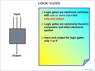
LOGIC GATES
Logic
gate
Input
Output
q Logic gates are electronic switches
with one or more input but
only one output
q Logic gates are commonly found in
computers and other electronic
system
q Input and output for logic gates
only 1 or 0
2. Author : Khairi
TRUTH TABLE
All inputs and outputs of logic gates can be displayed by
using a table
The table is known as truth table
LOGIC GATES
Input Output
A B C X
3. Author : Khairi
NOT GATE
Symbol for NOT GATE
A X
INPUT OUTPUT
A X
1
0
Truth table
0
1
Boolean expression
X = A
Output is opposite to input
LOGIC GATES
4. Author : Khairi
NOT GATE
A X
INPUT OUTPUT
A X
1
0
Truth table
0
1
Corresponding electric circuit
LOGIC GATES
Symbol for NOT GATE
5. Author : Khairi
A X
INPUT OUTPUT
A X
1
0
Truth table
0
1
Corresponding electric circuit
LOGIC GATES
Symbol for NOT GATE
NOT GATE
6. Author : Khairi
AND GATE
Boolean expression
X = A B
INPUT OUTPUT
A B X
0
0
0
1
1 0
1 1
0
0
0
1
A
B
X
Corresponding electric circuit
Choose all high
LOGIC GATES
7. Author : Khairi
Boolean expression
X = A B
INPUT OUTPUT
A B X
0
0
0
1
1 0
1 1
0
0
0
1
A
B
X
Corresponding electric circuit
LOGIC GATES
AND GATE
10. Author : Khairi
Truth table
A B X A B
=
Output for NAND GATE is opposite the output of AND GATE
0 0
X A B
=
A
B
LOGIC GATES
NAND GATE
11. Author : Khairi
Truth table
A B X A B
=
0 0
Input 00 for AND GATE produces 0 output
Inverting the output to get the output for AND GATE
1
0 1
X A B
=
A
B
LOGIC GATES
NAND GATE
12. Author : Khairi
Truth table
A B X A B
=
0 0 1
0 1 1
X A B
=
A
B
LOGIC GATES
Input 01 for AND GATE produces 0 output
Inverting the output to get the output for AND GATE
NAND GATE
13. Author : Khairi
Truth table
A B X A B
=
0 0 1
0 1 1
1 0 1
1 1 0
Corresponding electric circuit
X A B
=
A
B
LOGIC GATES
NAND GATE
14. Author : Khairi
OR GATE
A
B
X
Boolean expression for X
X = A + B
INPUT OUTPUT
A B X
0
0
0
1
1 0
1 1
0
1
1
1
Choose any one high
LOGIC GATES
15. Author : Khairi
OR GATE
A
B
X
Boolean expression for X
X = A + B
INPUT OUTPUT
A B X
0
0
0
1
1 0
1 1
0
1
1
1
Corresponding electric circuit
LOGIC GATES
16. Author : Khairi
NOR GATE
Boolean expression for X
X = A + B
A
B
X
INPUT OUTPUT
A B X
0
0
0
1
1 0
1 1
1
0
0
0
LOGIC GATES
17. Author : Khairi
COMBINATION OF LOGIC GATES
In the electronic circuit,logic gates are combined into various
combination to produce a desired output
LOGIC GATES
AND
NAND
AND
18. Author : Khairi
LOGIC GATES
COMBINATION OF LOGIC GATES
A
B
C
D
X
What is the Boolean expression for X
A B
19. Author : Khairi
LOGIC GATES
COMBINATION OF LOGIC GATES
A
B
C
D
X
What is the Boolean expression for X
A B
C D
20. Author : Khairi
LOGIC GATES
COMBINATION OF LOGIC GATES
A
B
C
D
X
What is the Boolean expression for X
A B
C D
A B C D
21. Author : Khairi
P
Q
X
Write the Boolean expression for X and state the equivalent
basic logic gate.
P + Q
P + Q
P
Q
X
Equivalent logic gate is NOR GATE
LOGIC GATES
COMBINATION OF LOGIC GATES
42. Author : Khairi
X
Draw the output for X on timing diagram
Get the input in binary number
1 0 1
0 0 1
Get the output in binary number
= 101
Draw the timing diagram for output X
LOGIC GATES
INPUT FROM TIMING DIAGRAM
43. Author : Khairi
INPUT P
INPUT Q
OUTPUT X
If P and Q are
the inputs
of AND GATE.
Draw the output X
LOGIC GATES
INPUT FROM TIMING DIAGRAM
44. Author : Khairi
EXERCISE
Draw the output if the inputs
are fed to NOR GATE
1 0 1 1 1 0 0
0 0 1 1 0 1 0
0 1 0 0 0 0 1
LOGIC GATES
46. Author : Khairi
ENRICHMENT PRACTICE
Light sensor
Body heat sensor
P
Q
X
Relay switch
Security lamp
Name the logic gate P.
NOT gate
47. Author : Khairi
ENRICHMENT PRACTICE
Light sensor
Body heat sensor
P
Q
X
Relay switch
Security lamp
Q is AND gate.Draw the AND gate by using two switches,batteries
and lamp.
48. Author : Khairi
ENRICHMENT PRACTICE
Light sensor
Body heat sensor
P
Q
X
Relay switch
Security lamp
Complete the truth table below for output X.
Input light sensor Input body heat sensor Output X
0
0
1
1
0
1
0
1
0
1
0
0
49. Author : Khairi
ENRICHMENT PRACTICE
Light sensor
Body heat sensor
P
Q
X
Relay switch
Security lamp
State the function of the relay switch in the circuit.
To switch on or off the security lamp.
50. Author : Khairi
Which of the following truth tables represents output R in the circuit ?
PAST YEARS QUESTION
51. Author : Khairi
Which of the following truth tables represents output R in the circuit ?
PAST YEARS QUESTION
52. Author : Khairi
What is the get X which produces the output in the truth table ?
A. AND
B. OR
C. NAND
D. NOR
PAST YEARS QUESTION
53. Author : Khairi
Which of the Boolean algebraic expression represents the output Z ?
A. Z = X Y
B. Z = X Y
C. Z = X Y
D. Z = X Y
Both S1 and S2 have to close
to produce Z high
PAST YEARS QUESTION
54. Author : Khairi
Which of the following output signals is produced by the logic
gate circuit ?
A. B. C. D.
0101
1001
1110
0110
1110
PAST YEARS QUESTION
56. Author : Khairi
Figure shows two combination of logic gates.
a. Name the logic gate M.
OR gate
b. Complete the truth table for P and Q
S1 S2
Output P
0
1
1
0
0
1
0
1
0
S1 S2
Output Q
0
1
1
0
0
1
1
1
1
PAST YEARS QUESTION
57. Author : Khairi
Figure shows the system used to control the level of pesticide in a bottle
Input S1 and S2 is “0” when they receive a low level of radiation and “1”
when they receive a high level of radiation.
a. State the level of the pesticide in the bottle if the input S1 is “0”.
Give your reason.
Level of pesticide in the bottle is high because it receives low radiation
due to less penetration of radioactive radiation
PAST YEARS QUESTION
58. Author : Khairi
Figure shows the system used to control the level of pesticide in a bottle
Input S1 and S2 is “0” when they receive a low level of radiation and “1”
when they receive a high level of radiation.
b. State the level of the pesticide in the bottle if the input S1 is “1”.
Give your reason.
Level of pesticide in the bottle is low because it receives high radiation
due to higher penetration of radioactive radiation
PAST YEARS QUESTION
59. Author : Khairi
Figure shows the system used to control the level of pesticide in a bottle
Input S1 and S2 is “0” when they receive a low level of radiation and “1”
when they receive a high level of radiation.
c. If the output of logic gate system is “1” when the volume of pesticide
accepted and “0” if it is rejected.Which combination of logic gate P or Q is
suitable to be used ?Give reason for your answer.
Combination of logic gate P because both S1 and S2 have to be “0” when the volume
is acceptable
PAST YEARS QUESTION