Mod mag m2000 datasheet badger meter electromagnetic flow meter_m-series
•
0 likes•95 views

Mod mag m2000 datasheet badger meter electromagnetic flow meter_m-series. ĐT: 028 77727979 - sales@envimart.vn - www.envimart.vn

Recommended
Recommended
More Related Content
What's hot
What's hot (20)
Similar to Mod mag m2000 datasheet badger meter electromagnetic flow meter_m-series
Similar to Mod mag m2000 datasheet badger meter electromagnetic flow meter_m-series (20)
More from ENVIMART
More from ENVIMART (20)
Recently uploaded
Recently uploaded (20)
Mod mag m2000 datasheet badger meter electromagnetic flow meter_m-series
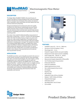
- 1. Electromagnetic Flow Meter M2000 MAG-DS-01047-EN-17 (July 2021) Product Data Sheet DESCRIPTION The Badger Meter ModMAG® M2000 is the result of years of research and field use of electromagnetic flow meter technology. Based on Faraday’s law of induction, these meters can measure water, wastewater, water-based fluids and other liquids that meet minimum electrical conductivity. Designed, developed and manufactured under strict quality standards, this meter features sophisticated, processor-based signal conversion with accuracies of ±0.20% of rate ±1 mm/s. The wide selection of liner and electrode materials helps provide maximum compatibility and minimum maintenance over a long operating period. The meter is best suited for bidirectional flow measurement of fluids with a conductivity > 5 µS/cm (> 20 µS/cm for demineralized water). The meter has high accuracy, is easy to use, and can be chosen for a wide variety of applications. The backlit, four-line display shows all actual flow measuring data, daily and complete information, including alarm messages. The standard transmitter has 4 programmable digital outputs, one digital input, power output and different interfaces. Integrated system self checkup makes putting into operation and service easier. For service purpose, the meter configuration can be kept or transferred to another meter without a new parametering via the optional back-up parameter function. APPLICATION The M2000 transmitter can be integrally mounted to the sensor or can be remote-mounted, if necessary and has many advantages over other conventional technologies. The meter targets a variety of applications and is well suited for the diverse water and wastewater treatment industry. The M2000 meter can accurately measure fluid flow—whether the fluid is water or a highly corrosive liquid, very viscous, contains a moderate amount of solids, or requires special handling. Today, electromagnetic meters are successfully used in industries including building automation, oil and gas, food and beverage, pharmaceutical, water and wastewater, and chemical. FEATURES • Available in sizes 0.25…78 in. (6…2000 mm) • Accuracy of ±0.2% of reading ±1 mm/s • Flow Range 0.03…12 m/s • Pulsed DC magnetic field for zero point stability • Integral and remote signal converter availability • Power Supply of 85…265V AC / 9…36V DC • Corrosion resistant liners for long life • Measurement largely independent of flow profile • User friendly programming procedure • Empty pipe detection • Power loss totalization • Digital signal processor (32-bit) • Non-volatile programming memory • LCD display • Rotating cover • IP67 Housing • Calibrated in state-of-the-art facilities • Modbus®, HART, Profibus DP, M-Bus • Integrated data logger • Verifications device • NSF/ANSI/CAN 61 and 372 listed • CSA certified
- 2. Electromagnetic Flow Meter, M2000 Page 2 July 2021 MAG-DS-01047-EN-17 ELECTRODES When looking from the end of the meter into the inside bore, the two measuring electrodes are positioned at three o’clock and nine o’clock. M2000 electromagnetic meters have an“empty pipe detection”feature. This is accomplished with a third electrode positioned in the meter at twelve o’clock. If this electrode is not covered by fluid for a minimum five-second duration, the meter displays an“empty pipe detection”condition, sends out an error message, if desired, and stops measuring to maintain accuracy. When the electrode again becomes covered with fluid, the error message disappears and the meter resumes measuring. As an option to using grounding rings, a grounding electrode (fourth electrode) can be built into the meter during manufacturing to assure proper grounding. The position of this electrode is at six o’clock. OPERATION The flow meter is a stainless steel tube lined with a non-conductive material. Outside the tube, two DC powered electromagnetic coils are positioned opposing each other. Perpendicular to these coils, two electrodes are inserted into the flow tube. Energized coils create a magnetic field across the whole diameter of the pipe. As a conductive fluid flows through the magnetic field, a voltage is induced across the electrodes. This voltage is proportional to the average flow velocity of the fluid and is measured by the two electrodes. The M2000 transmitter receives the sensor’s analog signal, amplifies that signal and converts it into digital information. At the processor level, the signal is analyzed through a series of sophisticated software algorithms. After separating the signal from electrical noise, it is converted into both analog and digital signals that are used to display rate of flow and totalization. With no moving parts in the flow stream, there is no pressure lost. Also, accuracy is not affected by temperature, pressure, viscosity or density and there is practically no maintenance required. SPECIFICATIONS OTE: N DN represents nominal diameter in mm. Transmitter Specifications Flow Range 0.10…39.4 ft/s (0.03…12 m/s) Accuracy ± 0.20% m.v. ± 1 mm/s OIML/MID: 2…12 in. (DN50…300) with 0d up and 0d downstream ±1% ≥ 0.5 ft/s (0.15 m/s) Repeatability ± 0.1% Power Supply AC Power Supply: 85…265V AC; Typical Power: 20V A or 15W; Maximum Power: 26V A or 20W Optional DC Power Supply: 10…36V DC; Typical Power: 10W; Maximum Power: 14W Analog Output 4…20 mA, 0…20 mA, 0…10 mA, 2…10 mA (programmable and scalable) Voltage sourced 24V DC isolated. Maximum loop resistance < 800 Ohms. Digital Output Four total, configurable 24V DC sourcing active output (up to 2),100 mA total, 50 mA each; sinking open collector output (up to four), 30V DC max, 100 mA each; AC solid-state relay (up to 2), 48V AC, 500 mA max Digital Input Max 30V DC (programmable – positive zero return, external totalizer reset or preset batch start) Frequency Output Scalable up to 10 kHz, open collector up to 1 kHz, solid-state relay Misc Output High/low flow alarm (0…100% of flow), error alarm, empty pipe alarm, flow direction, preset batch alarm, 24V DC supply, ADE Communication RS232 Modbus RTU; RS485 Modbus RTU, HART, Profibus DP require separate daughterboards Pulse Width Scalable up to 10 kHz, passive open collector up to 10 kHz, active switched 24V DC. Up to two outputs (forward and reverse). Pulse width programmable from 1…1000 ms or 50% duty cycle. Processing 32-bit DSP Empty Pipe Detection Field tunable for optimum performance based on specific application Excitation Frequency 1 Hz, 3.75 Hz, 7.5 Hz or 15 Hz (factory optimized to pipe diameter) Noise Dampening Programmable 0…30 seconds Low Flow Cut-Off Programmable 0…10% of maximum flow Galvanic Separation 250V Fluid Conductivity Minimum 5.0 µS/cm (minimum 20 µS/cm for demineralized water) Fluid Temperature With Remote Transmitter: PFA, PTFE & Halar 302° F (150° C) With Meter-Mounted Transmitter: Rubber 178° F, (80° C), PFA, PTFE & Halar 212° F (100° C) Ambient Temperature – 4…140° F (–20…60° C) Relative Humidity Up to 90 percent non-condensing Flow Direction Unidirectional or bidirectional two separate totalizers (programmable) Totalization Programmable/resettable Units of Measure Ounce, pound, liter, US gallon, imperial gallon, barrel, hectoliter, mega gallon, cubic meter, cubic feet, acre feet Display 4 x 20 character display with backlight Programming Three-button, external manual or remote
- 3. Product Data Sheet Page 3 July 2021 MAG-DS-01047-EN-17 Transmitter Housing Cast aluminum, powder-coated paint Mounting Meter mount or remote wall mount (bracket supplied) Locations Indoor and outdoor Meter Enclosure Classification Standard: NEMA 4X (IP67); Optional: Submersible NEMA 6P ((IP68) depth of 2 m for 72 hr), remote transmitter required Junction Box Enclosure Protection For remote transmitter option: powder-coated die-cast aluminum, NEMA 4 (IP67) Cable Entries M20 cable glands (3) Optional Stainless Steel Grounding Rings Meter Size Thickness of one ring Thickness of one ring (DIN Flanges) Up through 10 in. 0.135 in. (3.429 mm) 0.12 in. (3 mm) 12…78 in. 0.187 in. (4.750 mm) 0.12 in. (3 mm) NSF/ANSI/CAN 61 and 372 Listed Models with hard rubber liner, 4 in. size and larger; PTFE liner, all sizes OIML R49-1 MID MI-001 Size range: DN50…300 / 2…12 in. Minimum straight inlet flow: 0 DN /outlet flow: 0 DN Forward and reverse (bi-directional) flow on any orientation Ratio (Q3/Q1) up to 250 Accuracy Class 1 Token Features Data Logging (Blue token); Store/Restore (Red token); Firmware Upgrade (Black token) M2000 Transmitter Dimensions in. (mm) 3.90 (99) 7.09 (180) 7.09 (180) M20 (x3) 11.06 (281) M2000-1 2.36 (60) Ø 0.20 (5.2) 2.56 (65)
- 4. Electromagnetic Flow Meter, M2000 Page 4 July 2021 MAG-DS-01047-EN-17 Sensor Type II Specifications The electromagnetic sensor type II is not only available in a number of different flange process connections (DIN, ANSI, JIS, AWWA) but also in a number of liners like hard rubber, PTFE, PFA, or Halar. The sensor is configurable with up to 4 electrodes for measuring, empty pipe and grounding electrodes. Available in sizes from DN 6 TO DN 2000 and nominal pressures up to PN 100, the sensor type II is best suited for a variety of applications in the industry and the water/waste water industry. Size 1/4…78 in. (DN 6…2000) Flanges Standard: ANSI B16.5, AWWA, ISO 1092-1, JIS and more in carbon steel; Optional: 304 or 316 stainless steel Nominal Pressure Up to 1450 psi (100 bar) Pressure Rating Line sizes 1/4…24 in: In accordance with ASME B16.5 Class 150 or Flange Rating Class 300 Line sizes 26…72 in: AWWA C-207 Class D or Class E Flange Rating Protection Class NEMA 4X (IP67), optional NEMA 6P (IP68) Minimum Conductivity 5 µS/cm (20 µS/cm for demineralized water) Liner Material Hard/soft rubber 1…78 in. (DN 25…2000) 32…176° F (0…80° C) PTFE 1/2…24 in. (DN 15…600) –40…302° F (–40…150° C) Halar (ECTFE) 12 in. (DN 300) and larger –40…302° F (–40…150° C) PFA 1/4…3/8 in. (DN 6…10) — Electrodes Materials Hastelloy C (standard), Tantal Platinum / Gold plated, Platinum / Rhodium Housing Standard: Carbon steel welded; Optional: 316 or 304 stainless steel Electrode Materials Standard: Hastelloy C22; Optional: 316 stainless steel, gold/platinum plated, tantalum, platinum/rhodium Lay Length 1/4…3/4 in. (DN 6…20) 6.7 in. (170 mm) 1…2 in. (DN 25…50) 8.9 in. (225 mm) 2-1/2…4 in. (DN 65…100) 11.0 in. (280 mm) 5…8 in. (DN 125…200) 15.8 in. (400 mm) 10…14 in. (DN 250…350) 19.7 in. (500 mm) 16…28 in. (DN 400…700) 23.6 in. (600 mm) 30…40 in. (DN 750…1000) 31.5 in. (800 mm) 48…56 in. (DN 1200…1400) 39.4 in. (1000 mm) 64 in. (DN 1600) 63.0 in. (1600 mm) 72 in. (DN1800) 70.9 in. (1800 mm) 78 in. (DN2000) 78.7 in. (2000 mm) Sensor Type II Dimensions Remote Version in. (mm) Mounted Version in. (mm) A 4.80 (122) 3.15 (80) B1 C1 4.72 (120) K D d 2 x n M2000-3 DN 3.90 (99) 7.09 (180) 7.09 (180) M20 (x3) 11.06 (281) 2.36 (60) Ø 0.20 (5.2) 2.56 (65) A B2 C2 K D d 2 x n DN M2000-2 7.09 (180) 7.09 (180) M20 (x3) 3.27 (83)
- 5. Product Data Sheet Page 5 July 2021 MAG-DS-01047-EN-17 Size A Std* in. (mm) A ISO** in. (mm) B1 in. (mm) B2 in. (mm) C1 in. (mm) C2 in. (mm) with ANSI-flanges with DIN-flanges in. DN Ø D in. (mm) Ø K in. (mm) Ø d2×n in. (mm) Ø D in. (mm) Ø K in. (mm) Ø d2×n in. (mm) 1/4 6 6.7 (170) — 8.98 (228) 11.34 (288) 11.4 (288) 14.0 (356) 3.50 (88.9) 2.37 (60.3) 0.63 × 4 (15.9 × 4) 3.54 (90) 2.36 (60) 0.55 × 4 (14 × 4) 5/16 8 6.7 (170) — 8.98 (228) 11.34 (288) 11.4 (288) 14.0 (356) 3.50 (88.9) 2.37 (60.3) 0.63 × 4 (15.9 × 4) 3.54 (90) 2.36 (60) 0.55 × 4 (14 × 4) 3/8 10 6.7 (170) — 8.98 (228) 11.34 (288) 11.4 (288) 14.0 (356) 3.50 (88.9) 2.37 (60.3) 0.63 × 4 (15.9 × 4) 3.54 (90) 2.36 (60) 0.55 × 4 (14 × 4) 1/2 15 6.7 (170) 7.87 (200) 9.37 (238) 11.73 (298) 11.4 (288) 14.0 (356) 3.50 (88.9) 2.37 (60.3) 0.63 × 4 (15.9 × 4) 3.74 (95) 2.56 (65) 0.55 × 4 (14 × 4) 3/4 20 6.7 (170) 7.87 (200) 9.37 (238) 11.73 (298) 11.5 (293) 14.2 (361) 3.87 (98.4) 2.75 (69.8) 0.63 × 4 (15.9 × 4) 4.13 (105) 2.95 (75) 0.55 × 4 (14 × 4) 1 25 8.9 (225) 7.87 (200) 9.37 (238) 11.73 (298) 11.7 (298) 14.4 (366) 4.25 (107.9) 3.13 (79.4) 0.63 × 4 (15.9 × 4) 4.53 (115) 3.35 (85) 0.55 × 4 (14 × 4) 1-1/4 32 8.9 (225) 7.87 (200) 9.96 (253) 12.32 (313) 12.5 (318) 15.2 (386) 4.63 (117.5) 3.50 (88.9) 0.63 × 4 (15.9 × 4) 5.51 (140) 3.94 (100) 0.71 × 4 (18 × 4) 1-1/2 40 8.9 (225) 7.87 (200) 9.96 (253) 12.32 (313) 12.7 (322) 15.4 (390) 5.00 (127) 3.87 (98.4) 0.63 × 4 (15.9 × 4) 5.91 (150) 4.33 (110) 0.71 × 4 (18 × 4) 2 50 8.9 (225) 7.87 (200) 9.96 (253) 12.32 (313) 13.2 (335) 15.9 (403) 6.00 (152.4) 4.75 (120.6) 0.75 × 4 (19 × 4) 6.50 (165) 4.92 (125) 0.71 × 4 (18 × 4) 2-1/2 65 11.0 (280) 7.87 (200) 10.67 (271) 13.05 (331) 14.4 (366) 17.1 (434) 7.00 (177.8) 5.50 (139.7) 0.75 × 4 (19 × 4) 7.28 (185) 5.71 (145) 0.71 × 8 (18 × 8) 3 80 11.0 (280) 7.87 (200) 10.67 (271) 13.05 (331) 14.7 (372) 17.3 (440) 7.50 (190.5) 6.00 (152.4) 0.75 × 4 (19 × 4) 7.87 (200) 6.30 (160) 0.71 × 8 (18 × 8) 4 100 11.0 (280) 9.84 (250) 10.94 (278) 13.31 (338) 15.7 (398) 18.4 (466) 9.00 (228.6) 7.50 (190.5) 0.75 × 8 (19 × 8) 8.66 (220) 7.09 (180) 0.71 × 8 (18 × 8) 5 125 15.8 (400) 9.84 (250) 11.73 (298) 14.09 (358) 16.9 (430) 19.6 (498) 10.00 (254) 8.50 (215.9) 0.85 × 8 (22.2 × 8) 9.84 (250) 8.27 (210) 0.71 × 8 (18 × 8) 6 150 15.8 (400) 11.81 (300) 12.20 (310) 14.57 (370) 17.9 (456) 20.6 (524) 11.00 (279.4) 9.50 (241.3) 0.85 × 8 (22.2 × 8) 11.22 (285) 9.45 (240) 0.87 × 8 (22 × 8) 8 200 15.8 (400) 13.78 (350) 13.31 (338) 15.67 (398) 20.4 (518) 22.5 (572) 13.50 (342.9) 11.75 (298.4) 0.85 × 8 (22.2 × 8) 13.39 (340) 11.61 (295) 0.87 × 12 (22 × 12) 10 250 19.7 (500) 17.72 (450) 14.25 (362) 16.61 (422) 24.1 (613) 26.8 (681) 16.00 (406.4) 14.25 (361.9) 1.00 × 12 (25.4 × 12) 15.55 (395) 13.78 (350) 0.87 × 12 (22 × 12) 12 300 19.7 (500) 19.69 (500) 16.73 (425) 19.09 (485) 26.2 (666) 28.9 (734) 19.00 (482.6) 17.00 (431.8) 1.00 × 12 (25.4 × 12) 17.52 (445) 15.75 (400) 0.87 × 12 (22 × 12) 14 350 19.7 (500) 21.65 (550) 17.72 (450) 20.08 (510) 28.2 (716) 30.8 (782) 21.00 (533.4) 18.75 (476.2) 1.13 × 12 (28.6 × 12) 19.88 (505) 18.11 (460) 0.87 × 16 (22 × 16) 16 400 23.6 (600) 23.62 (600) 18.70 (475) 21.06 (535) 31.0 (788) 33.7 (856) 23.50 (596.9) 21.25 (539.7) 1.13 × 16 (28.6 × 16) 22.24 (565) 20.28 (515) 1.02 × 16 (26 × 16) 18 450 23.6 (600) — 19.69 (500) 22.05 (560) 32.4 (822) 35.0 (890) 25.00 (635.0) 22.75 (577.8) 1.25 × 16 31.7 × 16 24.21 (615) 22.24 (565) 1.02 × 20 (26 × 20) 20 500 23.6 (600) — 20.67 (525) 23.03 (585) 35.5 (901) 38.2 (969) 27.50 (698.5) 25.00 (635.0) 1.25 × 20 (31.7 × 20) 26.38 (670) 24.41 (620) 1.02 × 20 (26 × 20) 22 550 23.6 (600) — 21.65 (550) 24.02 (610) 36.9 (937) 39.6 (1005) 29.50 (749.3) 27.25 (692.1) 1.37 × 20 (34.9 × 20) — — — 24 600 23.6 (600) — 23.15 (588) 25.51 (648) 39.5 (1003) 42.2 (1071) 32.00 (812.8) 29.50 (749.3) 1.37 × 20 (34.9 × 20) 30.71 (780) 28.54 (725) 1.18 × 20 (30 × 20) 26 650 23.6 (600) — 24.13 (613) 26.50 (673) — — 32.25 (869.9) 31.75 (806.4) 1.37 × 24 (34.9 × 24) — — — 28 700 23.6 (600) — 24.61 (625) 26.97 (685) 44.0 (1118) 46.2 (1173) 36.50 (927.1) 34.00 (863.6) 1.38 × 28 (35.1 × 28) 35.24 (895) 33.07 (840) 1.18 × 24 (30 × 24) 30 750 31.5 (800) — 25.59 (650) 27.95 (710) 45.7 (1161) 48.3 (1228) 38.75 (984.2) 36.00 (914.4) 1.37 × 28 (34.9 × 28) — — — 32 800 31.5 (800) — 26.89 (683) 29.25 (743) 49.5 (1257) 52.2 (1325) 41.75 (1060.5) 38.50 (977.9) 1.63 × 28 (41.3 × 28) 39.96 (1015) 37.40 (950) 1.30 × 24 (33 × 24) 34 850 31.5 (800) — 27.87 (708) 30.24 (768) — — 43.75 (1111.2) 40.50 (1028.7) 1.63 × 32 (41.3 × 32) — — — 36 900 31.5 (800) — 28.54 (725) 30.91 (785) 54.1 (1374) 55.3 (1405) 46.00 (1168.4) 42.75 (1085.8) 1.63 × 32 (41.3 × 32) 43.90 (1115) 41.34 (1050) 1.30 × 28 (33 × 28) 38 950 31.5 (800) — 29.53 (750) 31.89 (810) — — 48.75 (1238.3) 45.25 (1149.4) 1.63 × 32 (41.3 × 32) — — — 40 1000 31.5 (800) — 31.10 (790) 33.46 (850) 57.4 (1457) 60.0 (1525) 53.00 (1346.2) 49.50 (1257.3) 1.63 × 36 (41.3 × 36) 48.43 (1230) 45.67 (1160) 1.42 × 28 (36 × 28)
- 6. Electromagnetic Flow Meter, M2000 Page 6 July 2021 MAG-DS-01047-EN-17 Size A Std* in. (mm) A ISO** in. (mm) B1 in. (mm) B2 in. (mm) C1 in. (mm) C2 in. (mm) with ANSI-flanges with DIN-flanges in. DN Ø D in. (mm) Ø K in. (mm) Ø d2×n in. (mm) Ø D in. (mm) Ø K in. (mm) Ø d2×n in. (mm) 42 1050 39.4 (1000) — — — 63.4 (1610) 66.0 (1675) — — — — — — 48 1200 39.4 (1000) — 35.43 (900) 37.80 (960) 67.2 (1707) 69.9 (1775) 59.51 (1511.5) 56.00 (1422.4) 1.63 × 44 (41.3 × 44) 57.28 (1455) 54.33 (1380) 1.54 × 32 (39 × 32) 54 1350 39.4 (1000) — 38.39 (975) 40.75 (1035) 73.0 (1927) 75.4 (1915) 66.25 (1682.8) 62.75 (1593.9) 1.88 × 44 (47.8 × 44) — — — 56 1400 39.4 (1000) — 39.37 (1000) 41.73 (1060) — — — — — 65.94 (1675) 62.60 (1590) 1.65 × 36 (42 × 36) Standard with ANSI-flanges 1/4…56 in. (DN 6 - 1400) pressure rate 150 psi (10 bar) with DIN flanges 1/4…8 in. (DN 6 – 200) pressure rate 230 psi (16 bar) 10…56 in. (DN 250 – 1400) pressure rate 150 psi (10 bar) * Standard **ISO 20456 MPORTANT I Flange Sizes ≤ 24 in., Standard: ANSI B16.5 Class 150 RF forged carbon steel; Optional: 300 lb forged carbon steel, 316 or 304 stainless steel Flange Sizes > 24 in., Standard: AWWA Class D Flanges RF forged carbon steel
- 7. Product Data Sheet Page 7 July 2021 MAG-DS-01047-EN-17 Weight and Flow Range Size Estimated Weight with M2000 Flow Range in. DN lb (kg) US Metric 1/4 6 8 (3.5) 0.0134…5.4 GPM 0.051…20.4 l/min 5/16 8 8 (3.5) 0.0239…9.6 GPM 0.09…36.2 l/min 3/8 10 8 (3.5) 0.0373…14.9 GPM 0.141…57 l/min 1/2 15 10 (4.5) 0.084…33.6 GPM 0.318…127 l/min 3/4 20 10 (4.5) 0.149…60 GPM 0.57…226 l/min 1 25 11 (5) 0.233…93 GPM 0.88…353 l/min 1-1/4 32 13 (6) 0.382…153 GPM 1.45…579 l/min 1-1/2 40 15.5 (7) 0.6…239 GPM 2.26…905 l/min 2 50 19 (8.5) 0.93…373 GPM 3.53…1,414 l/min 2-1/2 65 27.5 (12.5) 1.58…631 GPM 0.358…143 m³/h 3 80 31 (14) 2.39…956 GPM 0.54…217 m³/h 4 100 42 (19) 3.73…1,494 GPM 0.85…339 m³/h 5 125 53 (24) 5.8…2,334 GPM 1.33…530 m³/h 6 150 60.5 (27.5) 8.4…3,361 GPM 1.91…763 m³/h 8 200 87 (39.5) 14.9…5,975 GPM 3.39…1,357 m³/h 10 250 129 (58.5) 23.3…9,336 GPM 5.3…2,121 m³/h 12 300 204 (92.5) 33.6…13,444 GPM 7.6…3,054 m³/h 14 350 262 (119) 45.7…18,299 GPM 10.4…4,156 m³/h 16 400 344 (156) 60…23,901 GPM 13.6…5,429 m³/h 18 450 397 (180) 76…30,250 GPM 17.2…6,870 m³/h 20 500 470 (213) 93…37,345 GPM 21.2…8,482 m³/h 22 550 549 (249) 113…45,188 GPM 25.7…10,263 m³/h 24 600 617 (280) 134…53,777 GPM 30.5…12,214 m³/h 28 700 — 183…73,197 GPM 41.6…16,625 m³/h 30 750 930 (422) 210…84,027 GPM 47.7…19,085 m³/h 32 800 1171 (531) 239…95,604 GPM 54.3…21,714 m³/h 36 900 1378 (625) 302…120,999 GPM 69…27,482 m³/h 40 1000 — 373…149,381 GPM 85…33,928 m³/h 48 1200 1788 (811) 538…215,109 GPM 122…48,857 m³/h 56 1400 — 732…292,787 GPM 166…66,499 m³/h 60 1500 2112 (958) 840…336,108 GPM 191…76,338 m³/h 64 1600 2339 (1061) 956…382,416 GPM 217…86,856 m³/h 72 1800 3219 (1460) 1210…483,996 GPM 275…109,927 m³/h 78 2000 4101 (1860) 1494…597,525 GPM 339…135,713 m³/h
- 8. Electromagnetic Flow Meter, M2000 Page 8 July 2021 MAG-DS-01047-EN-17 Sensor Type III Specifications Thanks to its very short lay length, the sensor type III is often the right alternative to a lot of applications. Delivered with a PTFE liner, the sensor type III has a standard nominal pressure of PN 40. Size 1…4 in. (DN 25…100) Process Connection Wafer connection (in-between flange mounting) Nominal Pressure 580 psi (40 bar) Protection Class NEMA 4X (IP67), optional NEMA 6P (IP68) Minimum Conductivity 5 µS/cm (20 µS/cm for demineralized water) Liner Materials PTFE Electrode Material Hastelloy C (Standard), Tantal, Platinum / Gold Plated, Platinum / Rhodium Housing Carbon Steel / optional stainless steel Lay Length 1…2 in. (DN 25…50) 4 in. (100 mm) 2-1/2…4 in. (DN 65…100) 6 in. (150 mm) Sensor Type III Dimensions Remote Version in. (mm) Mounted Version in. (mm) B1 4.80 (122) 4.72 (120) 3.15 (80) DN M2000-5 D A 3.90 (99) 7.09 (180) 7.09 (180) M20 (x3) 11.06 (281) 2.36 (60) Ø 0.20 (5.2) 2.56 (65) A B2 DN M2000-4 D 7.09 (180) 7.09 (180) M20 (x3) 3.27 (83) in. DN A B1 B2 D 1 25 3.94 (100) 9.37 (238) 7.24 (184) 2.91 (74) 1-1/4 32 3.94 (100) 9.57 (243) 7.44 (189) 3.31 (84) 1-1/2 40 3.94 (100) 9.76 (248) 7.64 (194) 3.70 (94) 2 50 3.94 (100) 9.96 (253) 7.83 (199) 4.09 (104) 2-1/2 65 5.91 (150) 10.47 (266) 8.35 (212) 5.08 (129) 3 80 5.91 (150) 10.67 (271) 8.54 (217) 5.51 (140) 4 100 5.91 (150) 10.98 (279) 8.86 (225) 6.14 (156) 580 psi (40 bar)
- 9. Product Data Sheet Page 9 July 2021 MAG-DS-01047-EN-17 Sensor with Sanitary Process Connections Specifications The sensor model is available with Tri-Clamp® BS4825/ISO2852, DIN11851, and more process connections. The sanitary sensor is delivered in a stainless steel housing and with PTFE/PFA lining. Size 3/8…4 in. (DN 10…100) Process Connection Tri-Clamp BS4825/ISO2852, DIN 11851, customer specified, and more Nominal Pressure 145/230 psi (10/16 bar) Protection Class NEMA 4X (IP67), optional NEMA 6P (IP68) Minimum Conductivity 5 µS/cm (20 µS/cm for demineralized water) Liner Materials PTFE/PFA –40…302° F (–40…150° C) Electrode Material Standard: Hastelloy C; Optional: Tantal, Platinum / Gold plated, Platinum / Rhodium Housing Standard: Carbon Steel; Optional: Stainless Steel Lay Length Tri-Clamp Connection 3/8…2 in. (DN 10…50) 6 in. (145 mm) 2-1/2…4 in. (DN 65…100) 8 in. (200 mm) DIN 11851 Connection 3/8…3/4 in. (DN 10…20) 7 in. (175 mm) 1…2 in. (DN 25…50) 9 in. (225 mm) 2-1/2…4 in. (DN 65…100) 11 in. (280 mm) DIN 11851 Connection Dimensions Remote Version in. (mm) Mounted Version in. mm B1 A 4.72 (120) 4.80 (122) 3.15 (80) D DN M2000-7 3.90 (99) 7.09 (180) 7.09 (180) M20 (x3) 11.06 (281) 2.36 (60) Ø 0.20 (5.2) 2.56 (65) A B2 D DN M2000-9 M20 (x3) 3.27 (83) 7.09 (180) 7.09 (180) in. DN A B1 B2 D 3/8 10 6.69 (170) 9.37 (238) 7.24 (184) 2.91 (74) 1/2 15 6.69 (170) 9.37 (238) 7.24 (184) 2.91 (74) 3/4 20 6.69 (170) 9.37 (238) 7.24 (184) 2.91 (74) 1 25 8.86 (225) 9.37 (238) 7.24 (184) 2.91 (74) 1-1/4 32 8.86 (225) 9.57 (243) 7.44 (189) 3.31 (84) 1-1/2 40 8.86 (225) 9.76 (248) 7.64 (194) 3.70 (94) 2 50 8.86 (225) 9.96 (253) 7.83 (199) 4.09 (104) 2-1/2 65 11.02 (280) 10.47 (266) 8.35 (212) 5.08 (129) 3 80 11.02 (280) 10.67 (271) 8.54 (217) 5.51 (140) 4 100 11.02 (280) 10.98 (279) 8.86 (225) 6.14 (156) 230 psi (16 bar)
- 10. Electromagnetic Flow Meter, M2000 Page 10 July 2021 MAG-DS-01047-EN-17 Tri-Clamp Connection Dimensions Remote Version in. (mm) Mounted Version in. (mm) B1 4.72 (120) 4.80 (122) 3.15 (80) A D DN M2000-6 3.90 (99) 7.09 (180) 7.09 (180) M20 (x3) 11.06 (281) 2.36 (60) Ø 0.20 (5.2) 2.56 (65) B2 A 7.09 (180) D DN M2000-8 M20 (x3) 3.27 (83) 7.09 (180) in. DN A B1 B2 D 3/8 10 5.71 (145) 8.98 (228) 7.52 (191) 2.91 (74) 1/2 15 5.71 (145) 8.98 (228) 7.52 (191) 2.91 (74) 3/4 20 5.71 (145) 8.98 (228) 7.52 (191) 2.91 (74) 1 25 5.71 (145) 8.98 (228) 7.52 (191) 2.91 (74) 1-1/2 40 5.71 (145) 9.37 (238) 7.91 (201) 3.70 (94) 2 50 5.71 (145) 9.57 (243) 8.11 (206) 4.09 (104) 2-1/2 65 7.87 (200) 10.08 (256) 8.62 (219) 5.08 (129) 3 80 7.87 (200) 10.28 (261) 8.82 (224) 5.51 (140) 4 100 7.87 (200) 10.59 (269) 9.13 (232) 6.14 (156) 150 psi (10 bar) Tri-Clamp Connection OD ID BS4825 ISO2852 Size OD ID Size OD ID in. in. mm in. mm DN in. mm in. mm — — — — — 10 0.98 25.0 0.55 14.0 1/2 0.98 25.0 0.37 9.4 15 1.99 50.5 0.71 18.1 3/4 0.98 25.0 0.62 15.75 20 1.99 50.5 0.90 22.9 1 1.99 50.5 0.87 22.1 25 1.99 50.5 1.13 28.7 — — — — — 32 2.52 64.0 1.51 38.4 1-1/2 1.99 50.5 1.37 34.8 40 2.52 64.0 1.74 44.3 2 2.52 64.0 1.87 47.5 50 3.05 77.5 2.22 56.3 2-1/2 3.05 77.5 2.37 60.2 65 3.58 91.0 2.84 72.1 3 3.58 91.0 2.87 72.9 80 4.17 106.0 3.32 84.3 4 4.69 119.0 3.83 97.4 100 5.12 130.0 4.32 109.7 Nominal Pressure 145 psi (10 bar)
- 11. Product Data Sheet Page 11 July 2021 MAG-DS-01047-EN-17 PART NUMBER CONSTRUCTION If you are interested in a product configuration that is not designated for your region, please contact Badger Meter. Sensor and Transmitter Ordering Information for North America Hard Rubber Liner M2 - - - - - - M2000 Meter Type Electrodes & Grounding Amplifier Remote Cable Length Communications/ Outputs Wiring Method Unit of Measure Totalizer/ Flow Rate Testing & Tagging HARD RUBBER C-Steel 150# flanges HARD RUBBER C-Steel 300# flanges HARD RUBBER Stainless Steel 150# flanges Meter Type- Standard LL R1 R2 R4 1/4 in. 002 N/A N/A N/A 5/16 in. 003 N/A N/A N/A 3/8 in. 004 N/A N/A N/A 1/2 in. 005 N/A N/A N/A 3/4 in. 007 N/A — — — — — — — — — — — — — — — — — — — — — — — — — — — — — — — — — — — — — — — — — — — — — — — — — — — — — — — — — — — — — — — — — — — — — — — N/A N/A 1 in. 010 1-1/4 in. 012 1-1/2 in. 015 2 in. 020 2-1/2 in. 025 3 in. 030 4 in. 040 5 in. 050 6 in. 060 8 in. 080 10 in. 100 12 in. 120 14 in. 140 16 in. 160 18 in. 180 20 in. 200 22 in. 220 24 in. 240 28 in. 280 30 in. 300 32 in. 320 36 in. 360 40 in. 400 N/A 42 in. 420 N/A N/A 48 in. 480 N/A N/A 54 in. 540 N/A N/A Electrodes & Grounding Alloy C with 316 Stainless Steel Grounding Rings A Stainless Steel with 316 Stainless Steel Grounding Rings S Platinum Plated with 316 Stainless Steel Grounding Rings P Tantalum with 316 Stainless Steel Grounding Rings T Platinum/Rhodium with 316 Stainless Steel Grounding Rings R Alloy C Electrode and Grounding Electrode C Stainless Steel Electrode and Grounding Electrode D Platinum Plated Electrode and Grounding Electrode G Tantalum Electrode and Grounding Electrode L Platinum/Rhodium Electrode and Grounding Electrode H Amplifier Type 110/220V AC; Meter Mounted M 110/220V AC; Remote Mounted R 110/220V AC; Remote Mounted; Submersible S 110/220V AC; Remote Mounted; Submersible (IP68) T 24V DC; Meter Mounted E 24V DC; Remote Mounted F 24V DC; Remote Mounted; Submersible G 24V DC; Remote Mounted; Submersible (IP68) B Remote Cable Length None WW 5 ft. Standard Cable AA 10 ft. Standard Cable AB 15 ft. Standard Cable AC 30 ft. Standard Cable AF 50 ft. Standard Cable AK 75 ft. Standard Cable AR 100 ft. Standard Cable BW 125 ft. Standard Cable BE 150 ft. Standard Cable BK 175 ft. Standard Cable BR 200 ft. Standard Cable DW 225 ft. Standard Cable DE 250 ft. Standard Cable DK 275 ft. Standard Cable DR 300 ft. Standard Cable EW 325 ft. Standard Cable EE 350 ft. Standard Cable EK 375 ft. Standard Cable ER 400 ft. Standard Cable FW 425 ft. Standard Cable FE 450 ft. Standard Cable FK 475 ft. Standard Cable FR 500 ft. Standard Cable GW Communication/Outputs Standard Output S Standard Output with HART H Standard Output with PROFIBUS DP P Standard Output with MODBUS 485 RTU M Wiring Method None XX Twist Tight - 5 ft. (MTR, ASSY) TF Twist Tight - 10 ft. (MTR, ASSY) TH Twist Tight - 25 ft. (MTR, ASSY) TJ Twist Tight - 75 ft. (MTR, ASSY) TK Nicor - 6 ft. (MTR, ASSY) NG Nicor - 25 ft. (MTR, ASSY) NJ Itron - 5 ft. (MTR, ASSY) CF Itron - 25 ft. (MTR, ASSY) CJ Unit of Measure Totalizer/ Flow Rate Gallons/gallons per minute G Gallons/cubic feet per minute B Gallons/cubic meters per second D Cubic Meters/gallons per minute C Cubic Meters/cubic meters per second E Cubic Meters/cubic meters per minute T Cubic Meters/cubic meters per hour H Cubic Feet/gallons per minute F Cubic Feet/cubic feet per minute J Cubic Feet/cubic meters per hour K Liters/gallons per minute L Liters/liters per second N Liters/liters per minute P Liters/liters per hour Q Million Gallons/gallons per minute M Gallons/millions gallons per day R Acre Feet/gallons per minute A Second-Foot Day/cubic feet per second S Custom Units Z Testing & Tagging Factory Calibrated F 3rd Party Calibrated (See pricing on pg. 20) 3 Factory Calibrated/Stainless Steel Tag S 3rd Party Calibrated w/ Stainless Steel Tag (See pricing on pg. 20) T State of Kansas Certified K Detector
- 12. Electromagnetic Flow Meter, M2000 Page 12 July 2021 MAG-DS-01047-EN-17 Sensor and Transmitter Ordering Information for North America PTFE Liner M2 - - - - - - M2000 Meter Type Electrodes & grounding Amplifier Remote Cable Length Communications/ Outputs Wiring Method Unit of Measure Totalizer/ Flow Rate Testing and Tagging PTFE C-Steel 150# flanges PTFE C-Steel 300# flanges PTFE Stainless Steel 150# flanges PFA Stainless Steel 150# Flanges Meter Type- Standard LL P1 P2 P4 PA 1/4 in. 002 N/A N/A N/A 5/16 in. 003 N/A N/A N/A 3/8 in. 004 N/A — — — — — — — — — — — — — — — — — — — — — — — — — — — — — — — — — — — — — — — — — — — — — — — — — — — — — — — — — — — — — — — N/A N/A 1/2 in. 005 N/A 3/4 in. 007 N/A 1 in. 010 N/A 1-1/4 in. 012 N/A 1-1/2 in. 015 N/A 2 in. 020 N/A 2-1/2 in. 025 N/A 3 in. 030 N/A 4 in. 040 N/A 5 in. 050 N/A 6 in. 060 N/A 8 in. 080 N/A 10 in. 100 N/A 12 in. 120 N/A 14 in. 140 N/A 16 in. 160 N/A 18 in. 180 N/A 20 in. 200 N/A 22 in. 220 N/A 24 in. 240 N/A 28 in. 280 N/A N/A N/A N/A 30 in. 300 N/A N/A N/A N/A 32 in. 320 N/A N/A N/A N/A 36 in. 360 N/A N/A N/A N/A 40 in. 400 N/A N/A N/A N/A 42 in. 420 N/A N/A N/A N/A 48 in. 480 N/A N/A N/A N/A 54 in. 540 N/A N/A N/A N/A Electrodes & Grounding Alloy C with 316 Stainless Steel Grounding Rings A Stainless Steel with 316 Stainless Steel Grounding Rings S Platinum Plated with 316 Stainless Steel Grounding Rings P Tantalum with 316 Stainless Steel Grounding Rings T Platinum/Rhodium with 316 Stainless Steel Grounding Rings R Alloy C Electrode and Grounding Electrode C Stainless Steel Electrode and Grounding Electrode D Platinum Plated Electrode and Grounding Electrode G Tantalum Electrode and Grounding Electrode L Platinum/Rhodium Electrode and Grounding Electrode H Amplifier Type 110/220V AC; Meter Mounted M 110/220V AC; Remote Mounted R 110/220V AC; Remote Mounted; Submersible S 110/220V AC; Remote Mounted; Submersible (IP68) T 24V DC; Meter Mounted E 24V DC; Remote Mounted F 24V DC; Remote Mounted; Submersible G 24V DC; Remote Mounted; Submersible (IP68) B Remote Cable Length None WW 5 ft. Standard Cable AA 10 ft. Standard Cable AB 15 ft. Standard Cable AC 30 ft. Standard Cable AF 50 ft. Standard Cable AK 75 ft. Standard Cable AR 100 ft. Standard Cable BW 125 ft. Standard Cable BE 150 ft. Standard Cable BK 175 ft. Standard Cable BR 200 ft. Standard Cable DW 225 ft. Standard Cable DE 250 ft. Standard Cable DK 275 ft. Standard Cable DR 300 ft. Standard Cable EW 325 ft. Standard Cable EE 350 ft. Standard Cable EK 375 ft. Standard Cable ER 400 ft. Standard Cable FW 425 ft. Standard Cable FE 450 ft. Standard Cable FK 475 ft. Standard Cable FR 500 ft. Standard Cable GW Communications/Outputs Standard Output S Standard Output with HART H Standard Output with PROFIBUS DP P Standard Output with MODBUS 485 RTU M Wiring Method None XX Twist Tight - 5 ft. (MTR, ASSY) TF Twist Tight - 10 ft. (MTR, ASSY) TH Twist Tight - 25 ft. (MTR, ASSY) TJ Twist Tight - 75 ft. (MTR, ASSY) TK Nicor - 6 ft. (MTR, ASSY) NG Nicor - 25 ft. (MTR, ASSY) NJ Itron - 5 ft. (MTR, ASSY) CF Itron - 25 ft. (MTR, ASSY) CJ Unit of Measure Totalizer/ Flow Rate Gallons/gallons per minute G Gallons/cubic feet per minute B Gallons/cubic meters per second D Cubic Meters/gallons per minute C Cubic Meters/cubic meters per second E Cubic Meters/cubic meters per minute T Cubic Meters/cubic meters per hour H Cubic Feet/gallons per minute F Cubic Feet/cubic feet per minute J Cubic Feet/cubic meters per hour K Liters/gallons per minute L Liters/liters per second N Liters/liters per minute P Liters/liters per hour Q Million Gallons/gallons per minute M Gallons/millions gallons per day R Acre Feet/gallons per minute A Second-Foot Day/cubic feet per second S Custom Units Z Testing & Tagging Factory Calibrated F 3rd Party Calibrated (See pricing on pg. 20) 3 Factory Calibrated/Stainless Steel Tag S 3rd Party Calibrated w/ Stainless Steel Tag (See pricing on pg. 20) T State of Kansas Certified K Detector
- 13. Product Data Sheet Page 13 July 2021 MAG-DS-01047-EN-17 Sensor and Transmitter Ordering Information for North America Halar Liner M2 - - - - - - M2000 Meter Type Electrodes & Grounding Amplifier Remote Cable Length Communications/ Outputs Wiring Method Unit of Measure Totalizer/ Flow Rate Testing & Tagging HALAR C-Steel 150# flanges HALAR C-Steel 300# flanges HALAR Stainless Steel 150# flanges Meter Type- Standard LL H1 H2 H4 14 in. 140 16 in. 160 18 in. 180 20 in. 200 22 in. 220 24 in. 240 28 in. 280 30 in. 300 32 in. 320 36 in. 360 40 in. 400 N/ — — — — — — — — — — — — — — — — — — — — — — — — — — — — — — — — A Electrodes & Grounding Alloy C with 316 Stainless Steel Grounding Rings A Stainless Steel with 316 Stainless Steel Grounding Rings S Platinum Plated with 316 Stainless Steel Grounding Rings P Tantalum with 316 Stainless Steel Grounding Rings T Platinum/Rhodium with 316 Stainless Steel Grounding Rings R Alloy C Electrode and Grounding Electrode C Stainless Steel Electrode and Grounding Electrode D Platinum Plated Electrode and Grounding Electrode G Tantalum Electrode and Grounding Electrode L Platinum/Rhodium Electrode and Grounding Electrode H Amplifier Type 110/220V AC; Meter Mounted M 110/220V AC; Remote Mounted R 110/220V AC; Remote Mounted; Submersible S 110/220V AC; Remote Mounted; Submersible (IP68) T 24V DC; Meter Mounted E 24V DC; Remote Mounted F 24V DC; Remote Mounted; Submersible G 24V DC; Remote Mounted; Submersible (IP68) B Remote Cable Length None WW 5 ft. Standard Cable AA 10 ft. Standard Cable AB 15 ft. Standard Cable AC 30 ft. Standard Cable AF 50 ft. Standard Cable AK 75 ft. Standard Cable AR 100 ft. Standard Cable BW 125 ft. Standard Cable BE 150 ft. Standard Cable BK 175 ft. Standard Cable BR 200 ft. Standard Cable DW 225 ft. Standard Cable DE 250 ft. Standard Cable DK 275 ft. Standard Cable DR 300 ft. Standard Cable EW 325 ft. Standard Cable EE 350 ft. Standard Cable EK 375 ft. Standard Cable ER 400 ft. Standard Cable FW 425 ft. Standard Cable FE 450 ft. Standard Cable FK 475 ft. Standard Cable FR 500 ft. Standard Cable GW Communications/Outputs Standard Output S Standard Output with HART H Standard Output with PROFIBUS DP P Standard Output with MODBUS 485 RTU M Wiring Method None XX Twist Tight - 5 ft. (MTR, ASSY) TF Twist Tight - 10 ft. (MTR, ASSY) TH Twist Tight - 25 ft. (MTR, ASSY) TJ Twist Tight - 75 ft. (MTR, ASSY) TK Nicor - 6 ft. (MTR, ASSY) NG Nicor - 25 ft. (MTR, ASSY) NJ Itron - 5 ft. (MTR, ASSY) CF Itron - 25 ft. (MTR, ASSY) CJ Unit of Measure Totalizer/ Flow Rate Gallons/gallons per minute G Gallons/cubic feet per minute B Gallons/cubic meters per second D Cubic Meters/gallons per minute C Cubic Meters/cubic meters per second E Cubic Meters/cubic meters per minute T Cubic Meters/cubic meters per hour H Cubic Feet/gallons per minute F Cubic Feet/cubic feet per minute J Cubic Feet/cubic meters per hour K Liters/gallons per minute L Liters/liters per second N Liters/liters per minute P Liters/liters per hour Q Million Gallons/gallons per minute M Gallons/millions gallons per day R Acre Feet/gallons per minute A Second-Foot Day/cubic feet per second S Custom Units Z Testing & Tagging Factory Calibrated F 3rd Party Calibrated (See pricing on pg. 20) 3 Factory Calibrated/Stainless Steel Tag S 3rd Party Calibrated w/ Stainless Steel Tag (See pricing on pg. 20) T State of Kansas Certified K Detector
- 14. Electromagnetic Flow Meter, M2000 Page 14 July 2021 MAG-DS-01047-EN-17 Sensor Ordering Information for International MID - / - / - - / - Model MID electromagnetic flow meter MID Type Type 2 2 Type 3 3 Type 5 5 Type 6 6 Size DIN 6 to DN 2000 Pressure rate Process connection DIN flanges F ANSI flanges A Threads acc. DIN 11851 D Tri-Clamp® T Wafer W Material C-steel ST SST 1.4301 (ANSI 304) V2 SST 1.4404 (ANSI 316) V4 Liner PTFE PT (DN 6-10) PFA Hard rubber HG Softrubber WG Halar HA Electrodes Measure + empty pipe electrode ML Measure + grounding + empty pipe electrode MEL Electrode material Hastelloy C HC Tantalum TA Platinum/gold plated PG Platinum/Rhodium PR Housing C-steel St SST 1.4301 (ANSI 304) V2 SST 1.4404 (ANSI 306) V4 Example: MID 2 - 100 / 16 - F / St - HG - ML / HC - St Transmitter Ordering Information for International m Amplifier M2000 (85-265 VAC) M20A M2000 (9-36 VDC) M20D Mounted/remote/cable length Amplifier detector mounted M Remote version cable length R Remote amplifier with cable length Remote amplifier with 10 m cable length 10 Remote amplifier with 15 m cable length 15 Remote amplifier with 20 m cable length 20 Remote amplifier with 25 m cable length 25 Remote amplifier with 30 m cable length 30 Example: M10A R 15 m
- 15. Product Data Sheet Page 15 July 2021 MAG-DS-01047-EN-17 INTENTIONAL BLANK PAGE
- 16. Electromagnetic Flow Meter, M2000 www.badgermeter.com ModMAG is a registered trademark of Badger Meter, Inc. Other trademarks appearing in this document are the property of their respective entities. Due to continuous research, product improvements and enhancements, Badger Meter reserves the right to change product or system specifications without notice, except to the extent an outstanding contractual obligation exists. © 2021 Badger Meter, Inc. All rights reserved. Control. Manage. Optimize. Translated Document Number: MAG-DS-01896-ES-09, MAG-DS-03224-FR-06