SlideShare uma empresa Scribd logo
1 de 16
Baixar para ler offline
Ultra-Compact, Easy-To-Use Inverter TOSVERTTM
                                                                     TM


NEW
Single-phase 100V class 0.1 to 0.75kW
Single-phase 200V class 0.2 to 2.2kW
Three-phase 200V class 0.1 to 2.2kW

TOSVERT is a trademark of Toshiba Corporation.
Form

                                                                                               V F N C 1 S                                          2 0 0 7 P L                                             W
                                                                                              Model name             Input voltage         Applicable motor   Operation panel          Additional             Destinatio
                                                                                                                                               capacity                                 functions
                                                                                               TOSVERT               1:100V 115V             001: 0.1kW                P: Provided   L: EMI filter inside   W: World wide
                                                                                               VF-nC1 Series         2 200V 240V             002: 0.2kW                                                     - : Japan
     ISO 9001:                                    ISO 14001:                                                                                 004: 0.4kW
     VF-nC1 series is manufactured at             The works producing the VF-nC1                                                             007: 0.75kW
     the works, which has received the            series is registered as an                                                                 015: 1.5kW
     international quality assurance              environment management system                                                              022: 2.2kW
                                                                                               Number of
     standard ISO 9001 certification.             factory specified by ISO 14001.             power phases
     Registration No.: 200594
     Registration date: February 15, 2002                                                      S: 1-phase
                                                                                               None: 3-phase


 Models and applicable motors
                                                                       Applicable Motor Capacity (kW)
       Voltage
(Input/Rated Output)                        0.1                0.2              0.4          0.75              1.5                   2.2
                                                                                                                                                              Torque


 1   100V/3 200V


 1   200V/3 200V


 3   200V/3 200V                                                                                                                                                        0                500                1000
                                                                                                                                                                                                               Speed

 1   200V/3         200V
 (built-in EMI noise filter)
             Soon to be released
Compact, Easy-to-Use, Inverter
                                                   for Small-Sized Machines!
            The wide range of functions of the VF-nC1 meets various users’ needs,
                                      from simple speed control to steady torque at low speed.
                                                 The vertical contact-type main circuit terminal board
                                                                      and captive screws also ensure easy wiring.


                                                                                                                                        POINT
                                                                          Easy to Wire and Install
                                                                 Like most internal power distribution and control devices, the VF-nC1 has a
                                                                 vertical main circuit terminal board for smoother installation in switchboards.
                                                                 Wiring set-up is further improved by the use of captive screws on the main
                                                                 circuit terminal board. VF-nC1 inverters may also be installed side by side to save
                                                                 space.
                               This is a composite photograph.


                  POINT
                              Easy to Select                                                       Approval             Approval              Approval
                                                                                                   pending              pending               pending

             General-purpose Toshiba inverters have been developed for "Compliance with Global Standards." The three main series: the
             three-phase 200V, single-phase 200V and single-phase 100V series, comply with major international standards in addition,
on           several series of European models with a built-in EMI noise filter are also available. All of them have a wide range of
             functions.


                                                                                         POINT
                  Easy to Set Up and Operate                                                                         Contents
            150                                                                                                       Panel and operation procedure              3
                            Even novice inverter users can operate the VF-nC1 without difficulty by
                            using the RUN and STOP keys and the frequency adjusting knob on the
            100                                                                                                       Model and standard specifications          5
                            operation panel. The design also allows most functions be controlled
                            from the input terminals. A wizard function helps users with                              Standard specifications/outline drawing    6
                            complicated settings. Other functions, which allow easy operation of the
                                                                                                                      Standard connection                        7
                            VF-nC1, include a vector control function (which improves the torque
                        1
                            characteristic), a PI control function (useful for fans and pumps), and a                 Basic and extended parameters              9
     1500    2000 min
                            15-speed preset function.
                                                                                                                      To users of our inverters                 11

                                                                                                                      Optional external devices                 12
Panel and operation procedure


                                Example of wiring
                                                  VF-nC1
                            Power supply
                                                  /         /

                                                  /         /

                                                  /         /


                   The following configuration is available for
                   VFNC1(S)-           P -W type.

                                Power ON (Set-up parameter)
                                Displays “            ”
                                When the power is
                                ON at initialization...


                                Select the logic
                                and base motor
                                frequency.


                                Displays “     ”
                                during frequency
                                setting, and
                                upon completion.


                   Set-up parameter
                    Title

                                                                0      100         0
                                                          220(V)     220(V)     230(V)
                                                      1410(min-1) 1410(min-1) 1710(min-1)

                        ,   ,    ,      ,                 50.0(Hz)   50.0(Hz)   60.0(Hz)
Monitoring                                                                                    Setting
                                                                                                             Displays operation                                                                          Turn on the power.
                                                                                                             frequency.                                                                                       is displayed.


                                                                                                                      Pressing
                                                                                                                      the MON
                      Operation                                                                                       (monitor) key twice ...

        Turn on the power.                                                                                   Displays                                                                                    Displays “             ”.
                 is displayed.                                                                               the motor rotating
                                                                                                             direction.


        Pressing the RUN key
                                                                                                                                                                                                        Pressing key until
        and turning
                                                                                                               Press the UP key ...                                                                     “       ”is displayed ...
        the potentiometer dial ...

        Operates VF-nC1                                                                                     Displays operation                                                                           Displays “             ”.
        at the frequency                                                                                    frequency command
        set with the                                                                                        value.
        potentiometer.


             Turning                                                                                                                                                                                                Pressing
                                                                                                               Press the UP key ...                                                                                 the ENTER key ...
             the potentiometer dial ...

        Changes                                                                                              Displays load                                                                               Displays
        the frequency.                                                                                       current in                                                                                  the setting.
                                                                                                             (%/ampere)


                                                                                                             Pressing the UP key
                                                                                                             displays various data such                                                              Press the ENTER key
                                                                                                             as input voltage, output
                                                                                                             voltage, input/output
                                                                                                                                                                                                     after setting
      Pressing the STOP key ...                                                                              terminal status. Pressing                                                               a value with
                                                                                                             the MON (monitor) key ...                                                               the UP/DOWN
                                                                                                                                                                                                     key ...
        Decelerates                                                                                          Displays operation                                                                          Displays “        ”
        and stops                                                                                            frequency                                                                                  and the setting value
        the motor.                                                                                           (returns to
                                                                                                                                                                                                        alternately, and then
                                                                                                              the beginning).
                                                                                                                                                                                                        the setting is complete.


                                                                                                                                                                                                         If you press the Enter key without changing
                                                                                                                                                                                                         the setting, the next parameter ("dEC")
                                                                                                                                                                                                         is displayed.


 Item displayed Key operated   LED display                                Description                                                      Item displayed Key operated     LED display                               Description
                                             The operation frequency is displayed (during operation). (When the standard monitor                                                              The ON/OFF status of each of the control signal input
                                                                                                                                            Input terminal
                                             display selection parameter                         is set at 0 [operation frequency].)                                                          terminals (F, R, RST, S1, S2 and S3) is displayed in bits.
   Parameter                                 The first basic parameter "History function (                                 )" is                                                                             ON:
  setting mode                               displayed.                                                                                                                                                      OFF:
                                             The direction of rotation is displayed.                                                                                                                                                                 F
Direction of rotation                                                                                                                                                                                                    S3                          R
                                             ( : forward run,     : reverse run)
                                                                                                                                                                                                                         S2                          S1
Operation frequency
                                             The operation frequency command value is displayed.                                                                                              The ON/OFF status of each of the control signal output
    command                                                                                                                                Output terminal
                                                                                                                                                                                              terminals (OUT, FL) is displayed in bits.
                                             The inverter output current is displayed.                                                                                                                       ON:
  Load current
                                             (Default setting: unit %)
                                                                                                                                                                                                             OFF:
                                             The inverter input current is displayed.                                                                                                                                            FL                       OUT
  Input voltage
                                             (Default setting: unit %)
                                             The inverter output voltage is displayed.                                                      CPU1 version                                      The version of the CPU1 is displayed.
 Output voltage
                                             (Default setting: unit %)
                                                                                                                                            CPU2 version                                      The version of the CPU2 is displayed.
 Torque current                              The torque current is displayed in %.
                                                                                                                                           Memory version                                     The version of the memory mounted is displayed.
   PI feedback                               The PI feedback value is displayed.
                                             (Unit: processed amount)
                                                                                                                                                Past trip 1                                    The past trip 1 (displayed alternately at 0.5-sec. intervals)
  Inverter load
      factor                                 The inverter load factor is displayed in %.
                                                                                                                                                Past trip 2                                    The past trip 2 (displayed alternately at 0.5-sec. intervals)
  Output power                               The inverter output power is displayed in %.
                                                                                                                                                Past trip 3                                    The past trip 3 (displayed alternately at 0.5-sec. intervals)
    Operation
    frequency                                The operation frequency is displayed (during operation).                                           Past trip 4                                    The past trip 4 (displayed alternately at 0.5-sec. intervals)
                                                                                                                                             Cumulative                                        The cumulative operation time is displayed.
                                                                                                                                            operation time                                     (0.01 corresponds to 1 hour.)
                                                                                                                                          Note) 1. With the current unit selection parameter or voltage unit selection parameter, you can choose between percentage
                                                                                                                                                   and ampere (A) for current or between percentage and volt (V) for voltage, respectively.
Model and standard specifications
          Three-phase 200V
                       Item                                                                                                Specification
                   Input voltage                                                                                           3-phase 200V
              Applicable motor (kW)                               0.1                      0.2                       0.4                     0.75                      1.5                       2.2
                         Type                                                                                                  VFNC1
                         Form                                   2001P                    2002P                2004P                2007P                2015P                  2022P
 Rating


               Capacity (kVA) Note 1)                            0.3                      0.6                  1.0                  1.6                    2.9                   3.9
           Rated output current (A) Note 2)                      0.7                      1.4                  2.4                   4                     7.5                  10.0
            Rated output voltage Note 3)                                                                        3-phase 200V to 240V
                Overload current rating                                                                          60 seconds at 150%
Power
supply


                  Voltage-frequency                                                                        3-phase 200V to 240V - 50/60Hz
                 Allowable fluctuation                                                              Voltage +10%, -15% Note 4), frequency 5%
                Protective method                                                                          IP20 Enclosed type (JEM 1030)
                 Cooling method                                                                 Self-cooling                                                   Forced air-cooled
                      Color                                                                                        Munsel 5Y8/0.5
                   Charge lamp                                                            LED indicating the charge status of the capacitor in the main circuit


          1-phase 200V
                       Item                                                                                                Specification
                   Input voltage                                                                                           1-phase 200V
              Applicable motor (kW)                               0.1                      0.2                       0.4                     0.75                      1.5                       2.2
                         Type                                                                                                 VFNC1S
                         Form                                                            2002P                2004P                2007P                2015P                  2022P
 Rating


               Capacity (kVA) Note 1)                                                     0.6                   1.0                 1.6                    2.9                   3.9
           Rated output current (A) Note 2)                                               1.4                   2.4                  4                     7.5                  10.0
            Rated output voltage Note 3)                                                                         3-phase 200V to 240V
                Overload current rating                                                                           60 seconds at 150%
Power
supply


                  Voltage-frequency                                                                        1-phase 200V to 240V - 50/60Hz
                 Allowable fluctuation                                                              Voltage +10%, -15% Note 4), frequency 5%
                Protective method                                                                          IP20 Enclosed type (JEM 1030)
                 Cooling method                                                                            Self-cooling                                        Forced air-cooled
                      Color                                                                                         Munsel 5Y8/0.5
                   Charge lamp                                                            LED indicating the charge status of the capacitor in the main circuit


          1-phase 100V
                       Item                                                                                                Specification
                   Input voltage                                                                                           1-phase 100V
              Applicable motor (kW)                               0.1                      0.2                       0.4                     0.75                      1.5                       2.2
                         Type                                                                                                 VFNC1S
                         Form                                   1001P                    1002P                1004P                1007P
 Rating


               Capacity (kVA) Note 1)                            0.3                      0.6                  1.0                  1.6
           Rated output current (A) Note 2)                      0.7                      1.4                  2.4                   4
            Rated output voltage Note 3)                                                                        3-phase 200V to 230V
                Overload current rating                                                                          60 seconds at 150%
Power
supply


                  Voltage-frequency                                                                        1-phase 100V to 115V - 50/60Hz
                 Allowable fluctuation                                                              Voltage +10%, -15% Note 4), frequency 5%
                Protective method                                                                          IP20 Enclosed type (JEM 1030)
                 Cooling method                                                       Self-cooling                           Forced air-cooled
                      Color                                                                                        Munsel 5Y8/0.5
                   Charge lamp                                                            LED indicating the charge status of the capacitor in the main circuit


          1-phase 200V (built-in EMI noise filter)                                               Soon to be released
                        Item                                                                                            Specification
                   Input voltage                                                                           1-phase 200V (built-in EMI noise filter)
              Applicable motor (kW)                               0.1                      0.2                     0.4                  0.75                           1.5                       2.2
                           Type                                                                                            VFNC1S
                          Form                                                          2002PL                  2004PL                2007PL                         2015PL                   2022PL
 Rating


               Capacity (kVA) Note 1)                                                     0.6                      1.0                   1.6                           2.9                      3.9
           Rated output current (A) Note 2)                                               1.2                      2.3                    4                            7.5                     10.7
            Rated output voltage Note 3)                                                                            3-phase 200V to 240V
                Overload current rating                                                                              60 seconds at 150%
Power
supply


                  Voltage-frequency                                                                           1-phase 200V to 240V - 50/60Hz
                 Allowable fluctuation                                                                 Voltage +10%, -15% Note 4), frequency 5%
                Protective method                                                                             IP20 Enclosed type (JEM 1030)
                 Cooling method                                                                               Self-cooling                                                   Forced air-cooled
                       Color                                                                                           Munsel 5Y8/0.5
                   Charge lamp                                                                                              None
                    Built-in filter                                                                               EMI noise filter (Class B)
Note) 1. Capacity is calculated at 220V for the 200V models.
Note) 2. Indicates rated output current setting when the PWM carrier frequency (parameter F300) is 4kHz or less.
         If the PWM carrier frequency setting is fixed above 4kHz, the rated current needs to be reduced. If the PWM carrier frequency is set above 4kHz, it could fall automatically if an over-current flaws
         during acceleration or for any other reason, depending on the amount of current that flows.
         The default setting of the PWN carrier frequency is 12kHz. (Except for single phase 200V class built-in EMI noise filter)
Note) 3. Maximum output voltage is the same as the input voltage. The maximum output voltage of a single-phase 100V model is proportional to the supply voltage.
Note) 4.     10% when the inverter is used continuously (load of 100%).
Standard specifications/outline drawing
                                             Item                                                                                               Specification
  Principal control functions


                                          Control system                       Sinusoidal PWM control
                                       Related output voltage                  Adjustable within a range of 100 to 120% of the corrected supply voltage (200V) (Unadjustable to any voltage higher than the input voltage).
                                      Output frequency range                   0.5 to 200Hz, default setting: 0.5 to 80Hz, maximum frequency: 30 to 200Hz.
                                  Minimum setting steps of frequency           0.1Hz: operation panel setting, 0.2Hz: analog input (when the max. frequency is 100Hz).
                                                                               Digital setting: within ±0.5% of the max. frequency (-10 to +50˚C)
                                         Frequency accuracy                    Analog setting: within ±1.0% of the max. frequency (25 ˚C ± 10˚C)
                                 Voltage/frequency characteristics             V/f, slip frequency correction, base frequency, base frequency voltage and torque boost amount adjustable
                                                                               Volume on the front panel, external frequency volume (connectable to a volume with a rated impedance of 3-10k ), VI terminal (input
                                      Frequency setting signal                 impedance: 42k (voltage: 0-10Vdc) or 250 (current: 4-20mAdc)). The characteristic can be set arbitrarily by two-point setting.
                                 Start-up frequency/frequency jump             Adjustable within a range of 0.5 to 10Hz/Up to 1 frequency can be adjusted together with their widths.
                                   PWM carrier frequency (Note 1)              Selectable from among 2, 4, 8, 12 and 16kHz (Standard default setting: 12kHz or 4kHz for models with a built-in EMI noise filter)
                                   Acceleration/deceleration time              0.1 to 3000 seconds, switchable between acceleration/deceleration time 1 and 2.
  Operation specifications


                                                                               Number of times of retry selectable (Max. 10 times).
                                            Retry operation                    If the protection function is activated, the retry function restarts on completion of a check of the main circuit.
                                          Electric control                     Charging of capacitor (Deceleration time can be shortened by activating Forced Shortened Deceleration mode.)
                                      Control and drive circuit
                                         Dynamic braking                       Braking start-up frequency: 0 to maximum frequency, braking rate: 0 to 100%, braking time: 0 to 20 seconds.
                                                                               Forward/reverse run input signal, jog run input signal, standby signal, preset-speed operation input signal, reset input signal, etc./Switching
                                  Input terminal functions (selectable)        between sink/source.
                                                                               Frequency lower limit output signal, frequency upper limit output signal, low-speed detection output signal, specified speed attainment
                                 Output terminal functions (selectable)        output signal, etc. Open collector, RY output.
                                       Failure detection signal                1c-contact output: 250Vac/2A, cos = 0.4.
                                    Output for frequency meter/                PWM output: (1mAdc full-scale DC ammeter or 7.5Vdc full-scale DC ammeter/Rectifier-type AC voltmeter, 225% current Max. 1mAdc,
                                       output for ammeter                      7.5Vdc full-scale)
Protective


                                                                               Stall prevention, current limitation, over-current, output short circuit, over-voltage, over-voltage limitation, undervoltage, ground fault, power supply phase failure, output phase
 function


                                          Protective function                  failure overload protection by electronic thermal function, armature over-load at start-up, load-side over-torque at start, overheating prevention, detection of analog signal break.
                                 Protection against momentary power failure    Auto-restart/non-stop control after momentary power failure.
                                 Electronic thermal characteristics            Switching between standard motor/constant-torque VF motor, overload trip, overload stall selection.
                                                                               Frequency: inverter output frequency.
function
Display


                                                                               Alarm: stall alarm "C", overvoltage alarm "P", overload alarm "L", overheat alarm "H".
                                       4-digit 7-segments LED                  Status: inverter status (frequency, cause of activation of protective function, input/output voltage, output current, etc.) and parameter settings.
                                                                               Free-unit display: arbitrary unit (e.g. rotating speed) corresponding to output frequency.
                                             Indicator                         Lamps indicating the inverter status by lighting, such as RUN lamp and PRG lamp.
                                         Use environments                      Indoor, altitude: 1000m (Max.), not exposed to direct sunlight, corrosive gas, explosive gas or vibration (less than 5.9m/s2) (10 to 55Hz).
Environ-
 ments


                                        Ambient temperature                    -10 to 50˚C Note)1.2.3.
                                        Storage temperature                    -20 to +65˚C
                                         Relative humidity                     20 to 93% (free from condensation and vapor).
Note) 1. Above 40˚C: Remove the protective seal from the top of VF-nC1.
Note) 2. Side-by-side installation : 40˚C or less (Remove the protective seal from the top of VF-nC1).
Note) 3. Single-phase 200V models (built-in EMI noise filter) should be used where the ambient temperature will not rise above 40˚C.


                                External dimensions/weights


                                                                       Fig. A                                                                                                                        Fig. B

                            Applicable motor                                                                                                                 Dimensions (mm)                                                                           Approx. weight
                         Input voltage                                                 Type                                                                                                                                            Drawing
                                  (kW)                                                                                  W                   H                 D          W1                          H1                 D1                                  (kg)
                                   0.2                                        VFNC1S-2002P                                                                   100                                                                                            1.0
                                   0.4                                        VFNC1S-2004P                              72                                   124         60                                                                                 1.0
   1-phase 200V                   0.75                                        VFNC1S-2007P                                                                   137                                                                                            1.0
                                   1.5                                        VFNC1S-2015P                                                                                                                                                                  1.5
                                                                                                                       117                                    155                106
                                   2.2                                        VFNC1S-2022P                                                                                                                                                                  1.5
                                   0.1                                        VFNC1-2001P                                                                                                                                                                   1.0
                                                                                                                                                              100
                                   0.2                                        VFNC1-2002P                                                                                                                                                                   1.0
                                                                                                                        72                                                        60
                                   0.4                                        VFNC1-2004P                                                                     124                                                                                           1.0
   3-phase 200V
                                  0.75                                        VFNC1-2007P                                                                     137                                                                                           1.0
                                   1.5                                        VFNC1-2015P                                                                                                                                                                   1.5
                                                                                                                       117                142                 155                106                131                 8.5
                                   2.2                                        VFNC1-2022P                                                                                                                                                                   1.5
                                   0.1                                        VFNC1S-1001P                                                                                                                                                                  1.0
                                                                                                                                                              100
                                   0.2                                        VFNC1S-1002P                              72                                                        60                                                                        1.0
   1-phase 100V
                                   0.4                                        VFNC1S-1004P                                                                    124                                                                                           1.0
                                  0.75                                        VFNC1S-1007P                             117                                    155                106                                                                        1.5
                                   0.2                                        VFNC1S-2002PL                                                                   100                                                                                           1.0
                                   0.4                                        VFNC1S-2004PL                             72                                    124                 60                                                                        1.0
   1-phase 200V
                                  0.75                                        VFNC1S-2007PL                                                                   137                                                                                           1.0
(built-in EMI noise filter)
                                   1.5                                        VFNC1S-2015PL                                                                                                                                                                 1.5
                                                                                                                       117                                    155                106
                                   2.2                                        VFNC1S-2022PL                                                                                                                                                                 1.5
Standard connection


                                                                         Standard connection (common = CC)

     When using V1/S3 terminal as an analog input terminal (F109: 0 or 1)                                                                  When using V1/S3 terminal as a logic input terminal (F109: 2)


                                          DC reactor                                                                                                                               DC reactor
                                        (DCL: option)                                                                                                                            (DCL: option)

                                                                    P0            PA         PC                                                                                                     P0             PA        PC
             MCCB                                                                                                       Motor                      MCCB                                                                                                          Motor
                        R/L1               1                                                               U/T1                                                 R/L1               1                                                         U/T1
  Power                 S/L2                                                                               V/T2                        Power                    S/L2                                                                         V/T2
  supply                T/L3
                                                                           Main circuit
                                                                                                           W/T3
                                                                                                                         IM            supply                   T/L3
                                                                                                                                                                                                            Main circuit
                                                                                                                                                                                                                                             W/T3                     IM

                                  FLC                               Control                          F                Forward                                               FLC                       Control                        F                       Forward
     Fault output signal                                                                                                                  Fault output signal
                                                                     circuit                        R                                                                                                  circuit                       R
                                  FLB                                                                                 Reverse                                               FLB                                                                              Reverse
                                  FLA                                                               S1                Preset speed 1                                        FLA                                                    S1                        Preset speed 1
External
potentiometer                     P5                       VF-nC1                                   S2                Preset speed 2                                        P5                    VF-nC1                           S2                        Preset speed 2
(3-10k )                                                                                            CC                Common                                                                                                       CC                        Common
or input                          VI/S3            2       3
voltage signal                    CC
(0-10V)
Current signal                                                                 Connector for                                                                                                                     Connector for P15                    4
                                                                               optional devices                                                                                                                  optional devices
     4 20mA
                                                                                                                                                                                                                    VI/S3 2           3
                                                                                                                                                                                                                                                           Preset
                                                                                                                                                                                                                                                           speed 3
                                                                                                                                                                                                                                   CC
                                 FM/OUT                2 CC                 P15                                                                                             FM/OUT 2 CC
                       Meter                                                                                                                                    Meter
                                                                            RY                                                                                                                                  RY
  Frequency meter                                                                                                                      Frequency meter
        (Ammeter)                                                                                                                            (Ammeter)


                                                                                                                                                                                                                1-phase series

                                                                                                                                                                                                                                                    R/L1

                                                                                                                                                                                                                                                    S/L2
       1   Only VFNC1S-            PL has a built-in noise filter.
       2   The terminal can be switched between FM/OUT and VI by changing a parameter.
                                                                                                                                          1-phase series do not have T/L3 terminal.
       3   The terminal can also be used as an input terminal by changing a parameter.
       4   To use VI/S3 terminal as an input terminal, P15 and VI/S3 must be short-circuited with a resistor (recommended resistance: 4.7k -1/4W).


                                                                                               Source (common = P15)
           When using V1/S3 terminal as an analog input terminal (F109: 0 or 1)                                                        When using V1/S3 terminal as a logic input terminal (F109: 2)

                                             DC reactor                                                                                                              DC reactor
                                           (DCL: option)                                                                                                           (DCL: option)

                                                               P0         PA      PC                                                                                              P0         PA     PC
                      MCCB                                                                               Motor                                   MCCB                                                                      Motor
                              R/L1             1                                             U/T1                                                       R/L1            1                                        U/T1
             Power            S/L2                                                           V/T2                                       Power           S/L2                                                     V/T2
             supply           T/L3
                                                                    Main circuit
                                                                                             W/T3
                                                                                                         IM                             supply          T/L3
                                                                                                                                                                                       Main circuit
                                                                                                                                                                                                                 W/T3
                                                                                                                                                                                                                            IM

                                      FLC                      Control                   F           Forward                                                     FLC              Control                   F            Forward
                Fault output signal                                                                                                       Fault output signal
                                                                circuit                 R                                                                                          circuit                 R
                                      FLB                                                            Reverse                                                     FLB                                                     Reverse
                                      FLA                                               S1           Preset speed 1                                              FLA                                       S1            Preset speed 1
           External
           potentiometer              P5                VF-nC1                          S2           Preset speed 2                                                           VF-nC1                       S2            Preset speed 2
           (3-10k )                                                                 P15              Common                                                                                            P15               Common
           or input                   VI/S3 2          3
           voltage signal             CC
           (0-10V)
           Current signal                                            Connector for                                                                                                      Connector for
                                                                     optional devices                                                                                                   optional devices
                4 20mA
                                                                                                                                                                                                      VI/S3             Preset
                                                                                                                                                                                                                        speed 3
                                                                                                                                                                                                       P15
                                      FM/OUT 2 CC                    P15                                                                                        FM/OUT 2 CC
                             Meter                                                                                                                      Meter
                                                                                                                                                                                                                         1-phase series
                                                                     RY                                                                                                                 RY
           Frequency meter                                                                                                            Frequency meter                                                                                                     R/L1
       (Ammeter or voltmeter)                                                                                                     (Ammeter or voltmeter)
                                                                                                                                                                                                                                                          S/L2


      1    Only VFNC1S-           PL has a built-in noise filter.                                                                                                                                                         1-phase series do not have T/L3 terminal.

      2    The terminal can be switched between FM/OUT and VI by changing a parameter.
      3    The terminal can also be used as an input terminal by changing a parameter.
Main circuit
    Terminal symbol                                                                                                  Terminal function

                                 Grounding terminal for connecting inverter case. 2 grounding terminals.

                                 100V class: 1-phase 100V to 115V - 50/60Hz
     R/L1, S/L2, T/L3            200V class: 1-phase 200V to 240V - 50/60Hz, 3-phase 200V to 240V - 50/60Hz
                                   1-phase series have R/L1 and S/L2 terminal.
     U/T1, V/T2, W/T3            Connect to a (3-phase induction) motor.

             PC                  This is a negative potential terminal in the internal DC main circuit.

            PO, PA               Terminals for connecting a DC reactor (DCL: optional external device). Shorted when shipped from the factory. Before installing DCL remove the short bar.
                                 1-phase 100V models cannot be used with DC reactors. 1-phase 200V models (The models with a built-in EMI noise filter) are not provided with PO terminal.


    Control circuit terminal (Sink (common: CC))
  Terminal        Input/output                                                               Function                                                                      Specifications                           Wire size
   symbol

       F              Input                        Shorting across F-CC causes forward rotation; open causes slowdown and stop. (ST and CC are short-circuited.)
                                  programmable
                                   contact input
                                   Multifunction


                                                                                                                                                                          Dry contact input
                                                   Shorting across R-CC causes reverse rotation; open causes slowdown and stop. (ST and CC are short-circuited.)
       R              Input                                                                                                                                             15Vdc - 5mA or less
                                                      Shorting across R-CC/F-CC causes reverse rotation.
                                                                                                                                                                       Sink/source selectable
      S1              Input                        Shorting across S1-CC causes preset speed operation.                                                               by changing a parameter
      S2              Input                        Shorting across S2-CC causes preset speed operation.
                  Common to
      CC                            Control circuit's equipotential terminal.
                  input/output
      P5             Output         Power output for analog input setting.                                                                                         5Vdc (permissible load current: 10mAdc)   Solid wire: 0.3 to 1.5 (mm2)
                                                                                                                                                                                                             Stranded wire: 0.3 to 1.23 (mm2)
                                    Multifunction programmable analog input.                                                                                                    10Vdc:                       (AWG22 to 16)
                                    Standard default setting: Analog input 0-10Vdc and frequency 0-80Hz.                                                            (internal impedance: 42k )               Sheath strip length: 5 (mm)
     VI/S3            Input                                                                                                                                                    4-20mA:
                                    Possible to use as analog input (4 (0)-20mAdc) or contact input (programmable
                                    contact input) by changing a parameter.                                                                                        (internal impedance: 250k )

                                                                                                                                                                    1mA full-scale DC ammeter
                                    Multifunction programmable analog output. Standard default setting: Analog output frequency.                                    or 7.5Vdc (10Vdc) full-scale
                     Output         Meters connectable to FM/OUT: 1mAdc full-scale ammeter or 7.5Vdc (10Vdc) full-scale                                                    DC voltmeter
   FM/OUT
                                    voltmeter (PWM output).                                                                                                            Open collector output:
                                    Possible to switch to programmable open collector output by changing a parameter.                                                      24Vdc-50mA
      P15            Output         15Vdc power output.                                                                                                                      15Vdc-100mA
                                    Multifunction programmable relay contact output.                                                                                        250Vac-2A                        Solid wire: 0.3 to 1.5 (mm2)
     FLA                            Contact ratings: 250Vac - 2A (cos =1), 30Vdc - 1A, 250Vac - 1A (cos =0.4).                                                                                               Stranded wire: 0.3 to 1.5 (mm2)
                                                                                                                                                                    (cos =1): at resistance load
     FLB             Output
                                    Standard default setting: Monitoring of status of inverter's protection function. Activation                                             30Vdc-1A                        (AWG22 to 16)
     FLC                            of the protection function causes circuit FLA-FLC to close and circuit FLB-FLC to open.                                                                                  Sheath strip length: 6 (mm)
                                                                                                                                                                       250Vac-1A (cos =0.4)


    Selection of wiring devices
                                                                             Non-fuse circuit breaker                            Magnetic contactor
                   Capacity                                                                                                                                                                 Wire size (mm2)
   Voltage                                                                           (MCCB)                                            (MC)
                  applicable               Inverter model
    class           motor                                                    Rated current                 Type             Rated current                 Type        Main circuit                  DCL            Grounding cable
                     (kW)                                                         (A)                     Note 1)                (A)                     Note 1)     (mm2) Note 3)                 (mm2)            (mm2 Note 5)
                       0.1          VFNC1S-1001P                                       5                  NJ30N                       11                  C11J              2.0                                                3.5
  1-phase              0.2          VFNC1S-1002P                                      10                  NJ30N                       11                  C11J              2.0                                                3.5
 100V class
                       0.4          VFNC1S-1004P                                      15                  NJ30N                       11                  C11J              2.0                                                3.5
                       0.75         VFNC1S-1007P                                      30                  NJ30N                       18                  C20J              3.5                                                3.5
                       0.2          VFNC1S-2002P                   L                  10                  NJ30N                       11                  C11J              2.0                     1.25                       3.5
                       0.4          VFNC1S-2004P                   L                  15                  NJ30N                       11                  C11J              2.0                     1.25                       3.5
  1-phase
 200V class            0.75         VFNC1S-2007P L                                    20                  NJ30N                       11                  C11J              2.0                      2.0                       3.5
                       1.5          VFNC1S-2015P L                                    30                  NJ30N                       18                  C20J              3.5                      2.0                       3.5
                       2.2          VFNC1S-2022P L                                    40                  NJ50E                       35                  C35J              5.5                      2.0                       5.5
                       0.1          VFNC1-2001P                                        5                  NJ30N                       11                  C11J              2.0                     1.25                       3.5
                       0.2          VFNC1-2002P                                        5                  NJ30N                       11                  C11J              2.0                     1.25                       3.5
  3-phase              0.4          VFNC1-2004P                                        5                  NJ30N                       11                  C11J              2.0                     1.25                       3.5
 200V class            0.75         VFNC1-2007P                                       10                  NJ30N                       11                  C11J              2.0                      2.0                       3.5
                       1.5          VFNC1-2015P                                       15                  NJ30N                       11                  C11J              2.0                      2.0                       3.5
                       2.2          VFNC1-2022P                                       20                  NJ30N                       13                  C13J              2.0                      2.0                       3.5
Note) 1. Produced by Toshiba Schneider Electric Corporation.                                                                             Note) 4. For the control circuit, use shielded wires.
Note) 2. Be sure to attach surge killer to the exciting coil of the relay and the magnetic contactor.                                    Note) 5. For grounding, use a cable with a size equal to or larger than the above.
Note) 3. Size of the wires connected to the input terminals R, S and T and the output terminals U, V
         and W when the length of each wire does not exceed 30m.
Basic and extended parameters

                    Basic parameters                                                                                                                                                                                                Extended p
 Title                 Function                                    Adjustment range                        Default setting    Input parameters
                                                        Function of displaying 5 parameters grouped                           Title                  Function                                                Adjustment range         Default setting
         History function                               into one in the order of change                                                Low speed signal output frequency (Hz)                                                             0.6
                                                           Parameters can be edited within a group, too.                               Speed-reach setting frequency (Hz)                                                                 0.0

                                                        0                                                                                                                                   Voltage signal input           - or V
                                                                                                                                       Analog input/logic input                             Current signal input            - mA
                                                        1: Basic setting wizard                                                                                                                                                             0
                                                                                                                                       function selection                                   Contact input
                                                        2: Preset speed operation wizard
         Wizard function                                                                                         0                     Always active function selection (ST)            -        ,   -                                      1
                                                        3: Analog signal operation wizard
                                                        4: Motor 1/2 switching operation wizard                                        Input terminal selection 1 (F)                   -        ,   -                                      2
                                                        5: Torque up wizard     1                                                      Input terminal selection 2 (R)                   -        ,   -                                      3
         Command mode selection                         0: Terminal board 1: Operation panel                     1                     Input terminal selection 3 (S1)                  -        ,   -                                      6

                                                        0: Terminal board                                                              Input terminal selection 4 (S2)                  -        ,   -                                      7

         Frequency setting mode                         1: Operation panel                                                             Input terminal selection 5
                                                                                                                                                                                                                                            8
                                                        2: Internal potentiometer                                2                     (VI/S3)     5
         selection
                                                        3: Serial communication                                                                                                          Sink,                   Source,
                                                        4: Terminal board/internal volume switching                                    Sink/Source selection                                                                                 2
                                                                                                                                                                                        - ,              -       Invalid

                                                        -1: Open collector output                                                      Output terminal selection 1
                                                                                                                                                                                                                                            4
                                                        0: Output frequency                                                            (OUT/FM)      6
                                                        1: Output current                                                              Output terminal selection 3 (FL)                                                                    10
         FM/OUT terminal functions                      2: Set frequency                                                               Base frequency 2 (Hz)                                                                                 2
         selection                                      3: For adjustment (current fixed at 100%)                0
                                                                                                                                       Base frequency voltage 2 (V)                                                                          2
                                                        4: For adjustment (current fixed at 50%)
                                                        5: For adjustment (output of max. frequency)                                   Torque boost 2 (%)                                                                                    1
                                                        6: For adjustment (display of gain)                                            Motor thermal protection level 2 (%)                                                              100
                                                                                                                             5: This function is enabled if F109 is set at 2 (logic input).
         Meter adjustment
                                                                                                                             6: This function is enabled if FMSL (open collector output) is set at -1.
                                                        0:
                                                        1: Set at 50Hz
         Standard setting mode                          2: Set at 60Hz
         selection                                      3: Default setting
                                                                                                                 0            Frequency parameters
                                                        4: Trip clear                                                         Title                  Function                                                Adjustment range         Default setting
                                                        5: Cumulative operation time clear                                             VI/S3 reference point 1 setting (%)                                                                  0
         Forward/reverse selection (Operation panel)    0: Forward run 1: Reverse run                            0                     VI/S3 point 1 frequency (Hz)                                                                       0.0
                                                                                                                                       VI/S3 reference point 2 setting (%)                                                               100
         Acceleration time 1 (s)                                                                              10.0
                                                                                                                                       VI/S3 point 2 frequency (Hz)                                                                          2
         Deceleration time 1 (s)                                                                              10.0
                                                                                                                                       Starting frequency setting (Hz)                                                                    0.5
         Maximum frequency (Hz)                                                                                   2
                                                                                                                                       Operation starting frequency (Hz)                .                                                 0.0
         Upper limit frequency (Hz)                                                                               2                    Operation starting frequency hysteresis (Hz)     .                                                 0.0
         Lower limit frequency (Hz)                                                                            0.0                     DC braking starting frequency (Hz)                                                                 0.0

         Base frequency 1 (Hz)                                                                                    2                    DC braking current (%)                                ,                                             50
                                                                                                                                       DC braking time (s)                                                   ,                            1.0
                                                        0 (1.2): V/f                                                                   Jump frequency 1 (Hz)                                                                              0.0
         V/f control mode selection                     3: Sensorless vector control                             0
                                                                                                                                       Jumping width (Hz)                                                                                 0.0
                                                                                                                                       Preset speed operation frequencies 8 (Hz)                                                          0.0
         Torque boost 1 (%)                                                                                       3
                                                                                                                                       Preset speed operation frequencies 9 (Hz)                                                          0.0
         Motor thermal protection                                                                                                      Preset speed operation frequencies 10 (Hz)                                                         0.0
                                                                                                              100
         level 1 (%)                                                                                                                   Preset speed operation frequencies 11 (Hz)                                                         0.0
                                                                                 Overload Overload                                     Preset speed operation frequencies 12 (Hz)                                                         0.0
                                                       Setting                   protection stall                                      Preset speed operation frequencies 13 (Hz)                                                         0.0
                                                         0                                                                             Preset speed operation frequencies 14(Hz)                                                          0.0
                                                                                                                                       Preset speed operation frequencies 15 (Hz)                                                         0.0
                                                         1        Standard
                                                                    motor
                                                         2
         Electric thermal protection
         characteristics 4                               3                                                       0            Operation mode parameters
                                                         4                                                                    Title                  Function                                                Adjustment range         Default setting
                                                         5         VF motor                                                                                                           0: 2kHz
                                                                                                                                                                                      1: 2kHz (Random mode)
                                                         6                                                                                                                            2: 4kHz
                                                                                                                                       PWM carrier frequency                          3: 4kHz (Random mode)
                                                         7                                                                                                                                                                                  5      7
                                                                                                                                                                                      4: 8kHz
         Preset speed operation frequencies 1 (Hz)                                                             0.0                                                                    5: 12kHz
                                                                                                                                                                                      6: 16kHz
         Preset speed operation frequencies 2 (Hz)                                                             0.0
                                                                                                                                                                      0: Disabled
         Preset speed operation frequencies 3 (Hz)                                                             0.0                                                    1: At auto-restart after momentary stop
                                                                                                                                       Auto-restart control selection 2: When turning ST-CC on or off
         Preset speed operation frequencies 4 (Hz)                                                             0.0                                                                                                                          0
                                                                                                                                                                      3: At auto-restart after momentary stop
         Preset speed operation frequencies 5 (Hz)                                                             0.0                                                       or when turning ST-CC on or off
                                                                                                                                       Regenerative power ride-though control 0: Disabled 1: Enabled 2: Deceleration stop                   0
         Preset speed operation frequencies 6 (Hz)                                                             0.0
                                                                                                                                       Retry selection (Number of times) 0 (OFF), 1 - 10                                                    0
         Preset speed operation frequencies 7 (Hz)                                                             0.0
                                                                                                                                                                                      0: Disabled 1: Enabled
                                                                                                                                       Over voltage limit opertion                                                                          0
         Extended parameter                                                                                                                                                           2: Enabled (forced shortened deceleration)
         Search for changed settings                                                                                                   PI control                                     0: Disabled, 1: Enabled                               0
1: This parameter is valid only for VFNC1(S)-        P -W type.                                                                        Proportional (P) gain                                                                             0.30
2: The value is changed according to the set-up parameter condition. (refer to page 3)                                                 Integral (I) gain                                                                                 0.20
3: Parameter values vary depending on the capacity.
4: :Applicable,     :Inapplicable                                                                                            7: 2(4kHz) for VFNC1S-                      PL-          type.
Product Total
Product Total
Product Total
Product Total
Product Total
Product Total

Mais conteúdo relacionado

Mais procurados (18)

Sca1000 Fm A0%200 As
Sca1000 Fm A0%200 AsSca1000 Fm A0%200 As
Sca1000 Fm A0%200 As
 
EX B Ironless Linear Motors - PBASystems.com.sg
EX B Ironless Linear Motors - PBASystems.com.sgEX B Ironless Linear Motors - PBASystems.com.sg
EX B Ironless Linear Motors - PBASystems.com.sg
 
01. hrc din fuses 3 na
01. hrc din fuses  3 na01. hrc din fuses  3 na
01. hrc din fuses 3 na
 
Bci184 f
Bci184 fBci184 f
Bci184 f
 
Uci274 k
Uci274 kUci274 k
Uci274 k
 
Bg31189192
Bg31189192 Bg31189192
Bg31189192
 
Datasheet 3
Datasheet 3Datasheet 3
Datasheet 3
 
Mabd 50
Mabd 50Mabd 50
Mabd 50
 
74 Lcx08
74 Lcx0874 Lcx08
74 Lcx08
 
Smi1034
Smi1034Smi1034
Smi1034
 
Hci5 f
Hci5 fHci5 f
Hci5 f
 
Hci5 d
Hci5 dHci5 d
Hci5 d
 
DVD Player Multiple Output Di115 2
DVD Player Multiple Output Di115 2DVD Player Multiple Output Di115 2
DVD Player Multiple Output Di115 2
 
Sm1375
Sm1375Sm1375
Sm1375
 
Hci4 d
Hci4 dHci4 d
Hci4 d
 
Mcb price list_electrical_installations_a_to_z_w.e.f_1st_sep_2016
Mcb price list_electrical_installations_a_to_z_w.e.f_1st_sep_2016Mcb price list_electrical_installations_a_to_z_w.e.f_1st_sep_2016
Mcb price list_electrical_installations_a_to_z_w.e.f_1st_sep_2016
 
ABB Low Voltage LV Surge Arresters - ABB LOVOS 5 and LOVOS 10 Surge Arresters
ABB Low Voltage LV Surge Arresters - ABB LOVOS 5 and LOVOS 10 Surge ArrestersABB Low Voltage LV Surge Arresters - ABB LOVOS 5 and LOVOS 10 Surge Arresters
ABB Low Voltage LV Surge Arresters - ABB LOVOS 5 and LOVOS 10 Surge Arresters
 
Power Management IC Overview
Power Management IC OverviewPower Management IC Overview
Power Management IC Overview
 

Semelhante a Product Total

Impulse Voltage Test System
Impulse Voltage Test SystemImpulse Voltage Test System
Impulse Voltage Test Systemkennypowerhv
 
Kontrol vanası ve servomotorlar esbe lineer-vana-motorlari-ala-serisi
Kontrol vanası ve servomotorlar esbe lineer-vana-motorlari-ala-serisiKontrol vanası ve servomotorlar esbe lineer-vana-motorlari-ala-serisi
Kontrol vanası ve servomotorlar esbe lineer-vana-motorlari-ala-serisierdinc klima
 
LM2575 Voltage Regulator Datasheet
LM2575 Voltage Regulator DatasheetLM2575 Voltage Regulator Datasheet
LM2575 Voltage Regulator DatasheetYong Heui Cho
 
Super capacitor power bank usa
Super capacitor power bank usaSuper capacitor power bank usa
Super capacitor power bank usaSfereelect
 
Mitsubishi inverter inverter family
Mitsubishi inverter inverter familyMitsubishi inverter inverter family
Mitsubishi inverter inverter familyDien Ha The
 
Mitsubishi inverter inverter family
Mitsubishi inverter inverter familyMitsubishi inverter inverter family
Mitsubishi inverter inverter familyDien Ha The
 
Mitsubishi inverter inverter family dienhathe.vn
Mitsubishi inverter inverter family dienhathe.vnMitsubishi inverter inverter family dienhathe.vn
Mitsubishi inverter inverter family dienhathe.vnDien Ha The
 
Mitsubishi inverter fr-e500 catalog
Mitsubishi inverter fr-e500 catalogMitsubishi inverter fr-e500 catalog
Mitsubishi inverter fr-e500 catalogDien Ha The
 
Mitsubishi inverter fr-e500 catalog-dienhathe.vn
Mitsubishi inverter fr-e500 catalog-dienhathe.vnMitsubishi inverter fr-e500 catalog-dienhathe.vn
Mitsubishi inverter fr-e500 catalog-dienhathe.vnDien Ha The
 
Switch mode power supply
Switch mode power supplySwitch mode power supply
Switch mode power supplyAnish Das
 
Wide Vin DC/DC Converters: Reliable Power for Demanding Applications
		 Wide Vin DC/DC Converters: Reliable Power for Demanding Applications		 Wide Vin DC/DC Converters: Reliable Power for Demanding Applications
Wide Vin DC/DC Converters: Reliable Power for Demanding ApplicationsDesign World
 
02. sentron 3 wt brochure
02. sentron 3 wt brochure02. sentron 3 wt brochure
02. sentron 3 wt brochureangeloneha
 
Catalog đèn báo nút nhấn công tắc IDEC (Nhật Bản) - dòng TW
Catalog đèn báo nút nhấn công tắc IDEC (Nhật Bản) - dòng TWCatalog đèn báo nút nhấn công tắc IDEC (Nhật Bản) - dòng TW
Catalog đèn báo nút nhấn công tắc IDEC (Nhật Bản) - dòng TWCTY TNHH HẠO PHƯƠNG
 

Semelhante a Product Total (20)

Impulse Voltage Test System
Impulse Voltage Test SystemImpulse Voltage Test System
Impulse Voltage Test System
 
Kontrol vanası ve servomotorlar esbe lineer-vana-motorlari-ala-serisi
Kontrol vanası ve servomotorlar esbe lineer-vana-motorlari-ala-serisiKontrol vanası ve servomotorlar esbe lineer-vana-motorlari-ala-serisi
Kontrol vanası ve servomotorlar esbe lineer-vana-motorlari-ala-serisi
 
LM2575 Voltage Regulator Datasheet
LM2575 Voltage Regulator DatasheetLM2575 Voltage Regulator Datasheet
LM2575 Voltage Regulator Datasheet
 
Dec2001 contactor
Dec2001   contactorDec2001   contactor
Dec2001 contactor
 
01 - Contactor - Fuji Electric
 01 - Contactor - Fuji Electric 01 - Contactor - Fuji Electric
01 - Contactor - Fuji Electric
 
Axpert hivert series mv drive
Axpert hivert series mv driveAxpert hivert series mv drive
Axpert hivert series mv drive
 
Super capacitor power bank usa
Super capacitor power bank usaSuper capacitor power bank usa
Super capacitor power bank usa
 
Mitsubishi inverter inverter family
Mitsubishi inverter inverter familyMitsubishi inverter inverter family
Mitsubishi inverter inverter family
 
Mitsubishi inverter inverter family
Mitsubishi inverter inverter familyMitsubishi inverter inverter family
Mitsubishi inverter inverter family
 
Mitsubishi inverter inverter family dienhathe.vn
Mitsubishi inverter inverter family dienhathe.vnMitsubishi inverter inverter family dienhathe.vn
Mitsubishi inverter inverter family dienhathe.vn
 
Mitsubishi inverter fr-e500 catalog
Mitsubishi inverter fr-e500 catalogMitsubishi inverter fr-e500 catalog
Mitsubishi inverter fr-e500 catalog
 
Mitsubishi inverter fr-e500 catalog-dienhathe.vn
Mitsubishi inverter fr-e500 catalog-dienhathe.vnMitsubishi inverter fr-e500 catalog-dienhathe.vn
Mitsubishi inverter fr-e500 catalog-dienhathe.vn
 
MCCB Easy Pact ECLB
MCCB Easy Pact ECLBMCCB Easy Pact ECLB
MCCB Easy Pact ECLB
 
Switch mode power supply
Switch mode power supplySwitch mode power supply
Switch mode power supply
 
Wide Vin DC/DC Converters: Reliable Power for Demanding Applications
		 Wide Vin DC/DC Converters: Reliable Power for Demanding Applications		 Wide Vin DC/DC Converters: Reliable Power for Demanding Applications
Wide Vin DC/DC Converters: Reliable Power for Demanding Applications
 
02. sentron 3 wt brochure
02. sentron 3 wt brochure02. sentron 3 wt brochure
02. sentron 3 wt brochure
 
Acb2
Acb2Acb2
Acb2
 
ECE_468_Report_Sid_AB
ECE_468_Report_Sid_ABECE_468_Report_Sid_AB
ECE_468_Report_Sid_AB
 
3000 001
3000 0013000 001
3000 001
 
Catalog đèn báo nút nhấn công tắc IDEC (Nhật Bản) - dòng TW
Catalog đèn báo nút nhấn công tắc IDEC (Nhật Bản) - dòng TWCatalog đèn báo nút nhấn công tắc IDEC (Nhật Bản) - dòng TW
Catalog đèn báo nút nhấn công tắc IDEC (Nhật Bản) - dòng TW
 

Mais de ehiosa

10,000 kiloliter capacity_bdf_plant-1
10,000 kiloliter capacity_bdf_plant-110,000 kiloliter capacity_bdf_plant-1
10,000 kiloliter capacity_bdf_plant-1ehiosa
 
Cdm bhcs technology_pamphlet
Cdm bhcs technology_pamphletCdm bhcs technology_pamphlet
Cdm bhcs technology_pamphletehiosa
 
Bdf bhcs jatropha_plantation
Bdf bhcs jatropha_plantationBdf bhcs jatropha_plantation
Bdf bhcs jatropha_plantationehiosa
 
Consortium to produce_bio_fuels_from_jatropha[1]
Consortium to produce_bio_fuels_from_jatropha[1]Consortium to produce_bio_fuels_from_jatropha[1]
Consortium to produce_bio_fuels_from_jatropha[1]ehiosa
 
Kazeakari5
Kazeakari5Kazeakari5
Kazeakari5ehiosa
 
Glovapp Presentation140709
Glovapp Presentation140709Glovapp Presentation140709
Glovapp Presentation140709ehiosa
 
Hotel Isreals
Hotel IsrealsHotel Isreals
Hotel Isrealsehiosa
 
OZONE DEODORIZER
OZONE DEODORIZEROZONE DEODORIZER
OZONE DEODORIZERehiosa
 
OZONAIR deodorizes and sterilizer
OZONAIR deodorizes and sterilizerOZONAIR deodorizes and sterilizer
OZONAIR deodorizes and sterilizerehiosa
 
Business History Of Sd[1]
Business History Of Sd[1]Business History Of Sd[1]
Business History Of Sd[1]ehiosa
 
Nccij 1
Nccij 1Nccij 1
Nccij 1ehiosa
 

Mais de ehiosa (11)

10,000 kiloliter capacity_bdf_plant-1
10,000 kiloliter capacity_bdf_plant-110,000 kiloliter capacity_bdf_plant-1
10,000 kiloliter capacity_bdf_plant-1
 
Cdm bhcs technology_pamphlet
Cdm bhcs technology_pamphletCdm bhcs technology_pamphlet
Cdm bhcs technology_pamphlet
 
Bdf bhcs jatropha_plantation
Bdf bhcs jatropha_plantationBdf bhcs jatropha_plantation
Bdf bhcs jatropha_plantation
 
Consortium to produce_bio_fuels_from_jatropha[1]
Consortium to produce_bio_fuels_from_jatropha[1]Consortium to produce_bio_fuels_from_jatropha[1]
Consortium to produce_bio_fuels_from_jatropha[1]
 
Kazeakari5
Kazeakari5Kazeakari5
Kazeakari5
 
Glovapp Presentation140709
Glovapp Presentation140709Glovapp Presentation140709
Glovapp Presentation140709
 
Hotel Isreals
Hotel IsrealsHotel Isreals
Hotel Isreals
 
OZONE DEODORIZER
OZONE DEODORIZEROZONE DEODORIZER
OZONE DEODORIZER
 
OZONAIR deodorizes and sterilizer
OZONAIR deodorizes and sterilizerOZONAIR deodorizes and sterilizer
OZONAIR deodorizes and sterilizer
 
Business History Of Sd[1]
Business History Of Sd[1]Business History Of Sd[1]
Business History Of Sd[1]
 
Nccij 1
Nccij 1Nccij 1
Nccij 1
 

Último

Cyber Security Training in Office Environment
Cyber Security Training in Office EnvironmentCyber Security Training in Office Environment
Cyber Security Training in Office Environmentelijahj01012
 
Digital Transformation in the PLM domain - distrib.pdf
Digital Transformation in the PLM domain - distrib.pdfDigital Transformation in the PLM domain - distrib.pdf
Digital Transformation in the PLM domain - distrib.pdfJos Voskuil
 
Flow Your Strategy at Flight Levels Day 2024
Flow Your Strategy at Flight Levels Day 2024Flow Your Strategy at Flight Levels Day 2024
Flow Your Strategy at Flight Levels Day 2024Kirill Klimov
 
TriStar Gold Corporate Presentation - April 2024
TriStar Gold Corporate Presentation - April 2024TriStar Gold Corporate Presentation - April 2024
TriStar Gold Corporate Presentation - April 2024Adnet Communications
 
Annual General Meeting Presentation Slides
Annual General Meeting Presentation SlidesAnnual General Meeting Presentation Slides
Annual General Meeting Presentation SlidesKeppelCorporation
 
Innovation Conference 5th March 2024.pdf
Innovation Conference 5th March 2024.pdfInnovation Conference 5th March 2024.pdf
Innovation Conference 5th March 2024.pdfrichard876048
 
Guide Complete Set of Residential Architectural Drawings PDF
Guide Complete Set of Residential Architectural Drawings PDFGuide Complete Set of Residential Architectural Drawings PDF
Guide Complete Set of Residential Architectural Drawings PDFChandresh Chudasama
 
Church Building Grants To Assist With New Construction, Additions, And Restor...
Church Building Grants To Assist With New Construction, Additions, And Restor...Church Building Grants To Assist With New Construction, Additions, And Restor...
Church Building Grants To Assist With New Construction, Additions, And Restor...Americas Got Grants
 
Chapter 9 PPT 4th edition.pdf internal audit
Chapter 9 PPT 4th edition.pdf internal auditChapter 9 PPT 4th edition.pdf internal audit
Chapter 9 PPT 4th edition.pdf internal auditNhtLNguyn9
 
Youth Involvement in an Innovative Coconut Value Chain by Mwalimu Menza
Youth Involvement in an Innovative Coconut Value Chain by Mwalimu MenzaYouth Involvement in an Innovative Coconut Value Chain by Mwalimu Menza
Youth Involvement in an Innovative Coconut Value Chain by Mwalimu Menzaictsugar
 
Memorándum de Entendimiento (MoU) entre Codelco y SQM
Memorándum de Entendimiento (MoU) entre Codelco y SQMMemorándum de Entendimiento (MoU) entre Codelco y SQM
Memorándum de Entendimiento (MoU) entre Codelco y SQMVoces Mineras
 
8447779800, Low rate Call girls in New Ashok Nagar Delhi NCR
8447779800, Low rate Call girls in New Ashok Nagar Delhi NCR8447779800, Low rate Call girls in New Ashok Nagar Delhi NCR
8447779800, Low rate Call girls in New Ashok Nagar Delhi NCRashishs7044
 
Investment in The Coconut Industry by Nancy Cheruiyot
Investment in The Coconut Industry by Nancy CheruiyotInvestment in The Coconut Industry by Nancy Cheruiyot
Investment in The Coconut Industry by Nancy Cheruiyotictsugar
 
Pitch Deck Teardown: Geodesic.Life's $500k Pre-seed deck
Pitch Deck Teardown: Geodesic.Life's $500k Pre-seed deckPitch Deck Teardown: Geodesic.Life's $500k Pre-seed deck
Pitch Deck Teardown: Geodesic.Life's $500k Pre-seed deckHajeJanKamps
 
Financial-Statement-Analysis-of-Coca-cola-Company.pptx
Financial-Statement-Analysis-of-Coca-cola-Company.pptxFinancial-Statement-Analysis-of-Coca-cola-Company.pptx
Financial-Statement-Analysis-of-Coca-cola-Company.pptxsaniyaimamuddin
 
Global Scenario On Sustainable and Resilient Coconut Industry by Dr. Jelfina...
Global Scenario On Sustainable  and Resilient Coconut Industry by Dr. Jelfina...Global Scenario On Sustainable  and Resilient Coconut Industry by Dr. Jelfina...
Global Scenario On Sustainable and Resilient Coconut Industry by Dr. Jelfina...ictsugar
 
Cybersecurity Awareness Training Presentation v2024.03
Cybersecurity Awareness Training Presentation v2024.03Cybersecurity Awareness Training Presentation v2024.03
Cybersecurity Awareness Training Presentation v2024.03DallasHaselhorst
 

Último (20)

Cyber Security Training in Office Environment
Cyber Security Training in Office EnvironmentCyber Security Training in Office Environment
Cyber Security Training in Office Environment
 
Digital Transformation in the PLM domain - distrib.pdf
Digital Transformation in the PLM domain - distrib.pdfDigital Transformation in the PLM domain - distrib.pdf
Digital Transformation in the PLM domain - distrib.pdf
 
Corporate Profile 47Billion Information Technology
Corporate Profile 47Billion Information TechnologyCorporate Profile 47Billion Information Technology
Corporate Profile 47Billion Information Technology
 
Flow Your Strategy at Flight Levels Day 2024
Flow Your Strategy at Flight Levels Day 2024Flow Your Strategy at Flight Levels Day 2024
Flow Your Strategy at Flight Levels Day 2024
 
TriStar Gold Corporate Presentation - April 2024
TriStar Gold Corporate Presentation - April 2024TriStar Gold Corporate Presentation - April 2024
TriStar Gold Corporate Presentation - April 2024
 
Annual General Meeting Presentation Slides
Annual General Meeting Presentation SlidesAnnual General Meeting Presentation Slides
Annual General Meeting Presentation Slides
 
Innovation Conference 5th March 2024.pdf
Innovation Conference 5th March 2024.pdfInnovation Conference 5th March 2024.pdf
Innovation Conference 5th March 2024.pdf
 
Guide Complete Set of Residential Architectural Drawings PDF
Guide Complete Set of Residential Architectural Drawings PDFGuide Complete Set of Residential Architectural Drawings PDF
Guide Complete Set of Residential Architectural Drawings PDF
 
Church Building Grants To Assist With New Construction, Additions, And Restor...
Church Building Grants To Assist With New Construction, Additions, And Restor...Church Building Grants To Assist With New Construction, Additions, And Restor...
Church Building Grants To Assist With New Construction, Additions, And Restor...
 
Chapter 9 PPT 4th edition.pdf internal audit
Chapter 9 PPT 4th edition.pdf internal auditChapter 9 PPT 4th edition.pdf internal audit
Chapter 9 PPT 4th edition.pdf internal audit
 
Youth Involvement in an Innovative Coconut Value Chain by Mwalimu Menza
Youth Involvement in an Innovative Coconut Value Chain by Mwalimu MenzaYouth Involvement in an Innovative Coconut Value Chain by Mwalimu Menza
Youth Involvement in an Innovative Coconut Value Chain by Mwalimu Menza
 
Memorándum de Entendimiento (MoU) entre Codelco y SQM
Memorándum de Entendimiento (MoU) entre Codelco y SQMMemorándum de Entendimiento (MoU) entre Codelco y SQM
Memorándum de Entendimiento (MoU) entre Codelco y SQM
 
No-1 Call Girls In Goa 93193 VIP 73153 Escort service In North Goa Panaji, Ca...
No-1 Call Girls In Goa 93193 VIP 73153 Escort service In North Goa Panaji, Ca...No-1 Call Girls In Goa 93193 VIP 73153 Escort service In North Goa Panaji, Ca...
No-1 Call Girls In Goa 93193 VIP 73153 Escort service In North Goa Panaji, Ca...
 
8447779800, Low rate Call girls in New Ashok Nagar Delhi NCR
8447779800, Low rate Call girls in New Ashok Nagar Delhi NCR8447779800, Low rate Call girls in New Ashok Nagar Delhi NCR
8447779800, Low rate Call girls in New Ashok Nagar Delhi NCR
 
Investment in The Coconut Industry by Nancy Cheruiyot
Investment in The Coconut Industry by Nancy CheruiyotInvestment in The Coconut Industry by Nancy Cheruiyot
Investment in The Coconut Industry by Nancy Cheruiyot
 
Pitch Deck Teardown: Geodesic.Life's $500k Pre-seed deck
Pitch Deck Teardown: Geodesic.Life's $500k Pre-seed deckPitch Deck Teardown: Geodesic.Life's $500k Pre-seed deck
Pitch Deck Teardown: Geodesic.Life's $500k Pre-seed deck
 
Financial-Statement-Analysis-of-Coca-cola-Company.pptx
Financial-Statement-Analysis-of-Coca-cola-Company.pptxFinancial-Statement-Analysis-of-Coca-cola-Company.pptx
Financial-Statement-Analysis-of-Coca-cola-Company.pptx
 
Global Scenario On Sustainable and Resilient Coconut Industry by Dr. Jelfina...
Global Scenario On Sustainable  and Resilient Coconut Industry by Dr. Jelfina...Global Scenario On Sustainable  and Resilient Coconut Industry by Dr. Jelfina...
Global Scenario On Sustainable and Resilient Coconut Industry by Dr. Jelfina...
 
Japan IT Week 2024 Brochure by 47Billion (English)
Japan IT Week 2024 Brochure by 47Billion (English)Japan IT Week 2024 Brochure by 47Billion (English)
Japan IT Week 2024 Brochure by 47Billion (English)
 
Cybersecurity Awareness Training Presentation v2024.03
Cybersecurity Awareness Training Presentation v2024.03Cybersecurity Awareness Training Presentation v2024.03
Cybersecurity Awareness Training Presentation v2024.03
 

Product Total

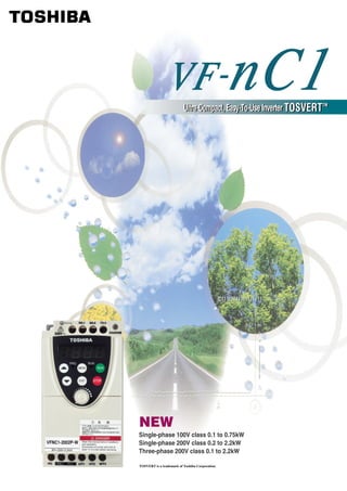
  • 1. Ultra-Compact, Easy-To-Use Inverter TOSVERTTM TM NEW Single-phase 100V class 0.1 to 0.75kW Single-phase 200V class 0.2 to 2.2kW Three-phase 200V class 0.1 to 2.2kW TOSVERT is a trademark of Toshiba Corporation.
  • 2. Form V F N C 1 S 2 0 0 7 P L W Model name Input voltage Applicable motor Operation panel Additional Destinatio capacity functions TOSVERT 1:100V 115V 001: 0.1kW P: Provided L: EMI filter inside W: World wide VF-nC1 Series 2 200V 240V 002: 0.2kW - : Japan ISO 9001: ISO 14001: 004: 0.4kW VF-nC1 series is manufactured at The works producing the VF-nC1 007: 0.75kW the works, which has received the series is registered as an 015: 1.5kW international quality assurance environment management system 022: 2.2kW Number of standard ISO 9001 certification. factory specified by ISO 14001. power phases Registration No.: 200594 Registration date: February 15, 2002 S: 1-phase None: 3-phase Models and applicable motors Applicable Motor Capacity (kW) Voltage (Input/Rated Output) 0.1 0.2 0.4 0.75 1.5 2.2 Torque 1 100V/3 200V 1 200V/3 200V 3 200V/3 200V 0 500 1000 Speed 1 200V/3 200V (built-in EMI noise filter) Soon to be released
  • 3. Compact, Easy-to-Use, Inverter for Small-Sized Machines! The wide range of functions of the VF-nC1 meets various users’ needs, from simple speed control to steady torque at low speed. The vertical contact-type main circuit terminal board and captive screws also ensure easy wiring. POINT Easy to Wire and Install Like most internal power distribution and control devices, the VF-nC1 has a vertical main circuit terminal board for smoother installation in switchboards. Wiring set-up is further improved by the use of captive screws on the main circuit terminal board. VF-nC1 inverters may also be installed side by side to save space. This is a composite photograph. POINT Easy to Select Approval Approval Approval pending pending pending General-purpose Toshiba inverters have been developed for "Compliance with Global Standards." The three main series: the three-phase 200V, single-phase 200V and single-phase 100V series, comply with major international standards in addition, on several series of European models with a built-in EMI noise filter are also available. All of them have a wide range of functions. POINT Easy to Set Up and Operate Contents 150 Panel and operation procedure 3 Even novice inverter users can operate the VF-nC1 without difficulty by using the RUN and STOP keys and the frequency adjusting knob on the 100 Model and standard specifications 5 operation panel. The design also allows most functions be controlled from the input terminals. A wizard function helps users with Standard specifications/outline drawing 6 complicated settings. Other functions, which allow easy operation of the Standard connection 7 VF-nC1, include a vector control function (which improves the torque 1 characteristic), a PI control function (useful for fans and pumps), and a Basic and extended parameters 9 1500 2000 min 15-speed preset function. To users of our inverters 11 Optional external devices 12
  • 4. Panel and operation procedure Example of wiring VF-nC1 Power supply / / / / / / The following configuration is available for VFNC1(S)- P -W type. Power ON (Set-up parameter) Displays “ ” When the power is ON at initialization... Select the logic and base motor frequency. Displays “ ” during frequency setting, and upon completion. Set-up parameter Title 0 100 0 220(V) 220(V) 230(V) 1410(min-1) 1410(min-1) 1710(min-1) , , , , 50.0(Hz) 50.0(Hz) 60.0(Hz)
  • 5. Monitoring Setting Displays operation Turn on the power. frequency. is displayed. Pressing the MON Operation (monitor) key twice ... Turn on the power. Displays Displays “ ”. is displayed. the motor rotating direction. Pressing the RUN key Pressing key until and turning Press the UP key ... “ ”is displayed ... the potentiometer dial ... Operates VF-nC1 Displays operation Displays “ ”. at the frequency frequency command set with the value. potentiometer. Turning Pressing Press the UP key ... the ENTER key ... the potentiometer dial ... Changes Displays load Displays the frequency. current in the setting. (%/ampere) Pressing the UP key displays various data such Press the ENTER key as input voltage, output voltage, input/output after setting Pressing the STOP key ... terminal status. Pressing a value with the MON (monitor) key ... the UP/DOWN key ... Decelerates Displays operation Displays “ ” and stops frequency and the setting value the motor. (returns to alternately, and then the beginning). the setting is complete. If you press the Enter key without changing the setting, the next parameter ("dEC") is displayed. Item displayed Key operated LED display Description Item displayed Key operated LED display Description The operation frequency is displayed (during operation). (When the standard monitor The ON/OFF status of each of the control signal input Input terminal display selection parameter is set at 0 [operation frequency].) terminals (F, R, RST, S1, S2 and S3) is displayed in bits. Parameter The first basic parameter "History function ( )" is ON: setting mode displayed. OFF: The direction of rotation is displayed. F Direction of rotation S3 R ( : forward run, : reverse run) S2 S1 Operation frequency The operation frequency command value is displayed. The ON/OFF status of each of the control signal output command Output terminal terminals (OUT, FL) is displayed in bits. The inverter output current is displayed. ON: Load current (Default setting: unit %) OFF: The inverter input current is displayed. FL OUT Input voltage (Default setting: unit %) The inverter output voltage is displayed. CPU1 version The version of the CPU1 is displayed. Output voltage (Default setting: unit %) CPU2 version The version of the CPU2 is displayed. Torque current The torque current is displayed in %. Memory version The version of the memory mounted is displayed. PI feedback The PI feedback value is displayed. (Unit: processed amount) Past trip 1 The past trip 1 (displayed alternately at 0.5-sec. intervals) Inverter load factor The inverter load factor is displayed in %. Past trip 2 The past trip 2 (displayed alternately at 0.5-sec. intervals) Output power The inverter output power is displayed in %. Past trip 3 The past trip 3 (displayed alternately at 0.5-sec. intervals) Operation frequency The operation frequency is displayed (during operation). Past trip 4 The past trip 4 (displayed alternately at 0.5-sec. intervals) Cumulative The cumulative operation time is displayed. operation time (0.01 corresponds to 1 hour.) Note) 1. With the current unit selection parameter or voltage unit selection parameter, you can choose between percentage and ampere (A) for current or between percentage and volt (V) for voltage, respectively.
  • 6. Model and standard specifications Three-phase 200V Item Specification Input voltage 3-phase 200V Applicable motor (kW) 0.1 0.2 0.4 0.75 1.5 2.2 Type VFNC1 Form 2001P 2002P 2004P 2007P 2015P 2022P Rating Capacity (kVA) Note 1) 0.3 0.6 1.0 1.6 2.9 3.9 Rated output current (A) Note 2) 0.7 1.4 2.4 4 7.5 10.0 Rated output voltage Note 3) 3-phase 200V to 240V Overload current rating 60 seconds at 150% Power supply Voltage-frequency 3-phase 200V to 240V - 50/60Hz Allowable fluctuation Voltage +10%, -15% Note 4), frequency 5% Protective method IP20 Enclosed type (JEM 1030) Cooling method Self-cooling Forced air-cooled Color Munsel 5Y8/0.5 Charge lamp LED indicating the charge status of the capacitor in the main circuit 1-phase 200V Item Specification Input voltage 1-phase 200V Applicable motor (kW) 0.1 0.2 0.4 0.75 1.5 2.2 Type VFNC1S Form 2002P 2004P 2007P 2015P 2022P Rating Capacity (kVA) Note 1) 0.6 1.0 1.6 2.9 3.9 Rated output current (A) Note 2) 1.4 2.4 4 7.5 10.0 Rated output voltage Note 3) 3-phase 200V to 240V Overload current rating 60 seconds at 150% Power supply Voltage-frequency 1-phase 200V to 240V - 50/60Hz Allowable fluctuation Voltage +10%, -15% Note 4), frequency 5% Protective method IP20 Enclosed type (JEM 1030) Cooling method Self-cooling Forced air-cooled Color Munsel 5Y8/0.5 Charge lamp LED indicating the charge status of the capacitor in the main circuit 1-phase 100V Item Specification Input voltage 1-phase 100V Applicable motor (kW) 0.1 0.2 0.4 0.75 1.5 2.2 Type VFNC1S Form 1001P 1002P 1004P 1007P Rating Capacity (kVA) Note 1) 0.3 0.6 1.0 1.6 Rated output current (A) Note 2) 0.7 1.4 2.4 4 Rated output voltage Note 3) 3-phase 200V to 230V Overload current rating 60 seconds at 150% Power supply Voltage-frequency 1-phase 100V to 115V - 50/60Hz Allowable fluctuation Voltage +10%, -15% Note 4), frequency 5% Protective method IP20 Enclosed type (JEM 1030) Cooling method Self-cooling Forced air-cooled Color Munsel 5Y8/0.5 Charge lamp LED indicating the charge status of the capacitor in the main circuit 1-phase 200V (built-in EMI noise filter) Soon to be released Item Specification Input voltage 1-phase 200V (built-in EMI noise filter) Applicable motor (kW) 0.1 0.2 0.4 0.75 1.5 2.2 Type VFNC1S Form 2002PL 2004PL 2007PL 2015PL 2022PL Rating Capacity (kVA) Note 1) 0.6 1.0 1.6 2.9 3.9 Rated output current (A) Note 2) 1.2 2.3 4 7.5 10.7 Rated output voltage Note 3) 3-phase 200V to 240V Overload current rating 60 seconds at 150% Power supply Voltage-frequency 1-phase 200V to 240V - 50/60Hz Allowable fluctuation Voltage +10%, -15% Note 4), frequency 5% Protective method IP20 Enclosed type (JEM 1030) Cooling method Self-cooling Forced air-cooled Color Munsel 5Y8/0.5 Charge lamp None Built-in filter EMI noise filter (Class B) Note) 1. Capacity is calculated at 220V for the 200V models. Note) 2. Indicates rated output current setting when the PWM carrier frequency (parameter F300) is 4kHz or less. If the PWM carrier frequency setting is fixed above 4kHz, the rated current needs to be reduced. If the PWM carrier frequency is set above 4kHz, it could fall automatically if an over-current flaws during acceleration or for any other reason, depending on the amount of current that flows. The default setting of the PWN carrier frequency is 12kHz. (Except for single phase 200V class built-in EMI noise filter) Note) 3. Maximum output voltage is the same as the input voltage. The maximum output voltage of a single-phase 100V model is proportional to the supply voltage. Note) 4. 10% when the inverter is used continuously (load of 100%).
  • 7. Standard specifications/outline drawing Item Specification Principal control functions Control system Sinusoidal PWM control Related output voltage Adjustable within a range of 100 to 120% of the corrected supply voltage (200V) (Unadjustable to any voltage higher than the input voltage). Output frequency range 0.5 to 200Hz, default setting: 0.5 to 80Hz, maximum frequency: 30 to 200Hz. Minimum setting steps of frequency 0.1Hz: operation panel setting, 0.2Hz: analog input (when the max. frequency is 100Hz). Digital setting: within ±0.5% of the max. frequency (-10 to +50˚C) Frequency accuracy Analog setting: within ±1.0% of the max. frequency (25 ˚C ± 10˚C) Voltage/frequency characteristics V/f, slip frequency correction, base frequency, base frequency voltage and torque boost amount adjustable Volume on the front panel, external frequency volume (connectable to a volume with a rated impedance of 3-10k ), VI terminal (input Frequency setting signal impedance: 42k (voltage: 0-10Vdc) or 250 (current: 4-20mAdc)). The characteristic can be set arbitrarily by two-point setting. Start-up frequency/frequency jump Adjustable within a range of 0.5 to 10Hz/Up to 1 frequency can be adjusted together with their widths. PWM carrier frequency (Note 1) Selectable from among 2, 4, 8, 12 and 16kHz (Standard default setting: 12kHz or 4kHz for models with a built-in EMI noise filter) Acceleration/deceleration time 0.1 to 3000 seconds, switchable between acceleration/deceleration time 1 and 2. Operation specifications Number of times of retry selectable (Max. 10 times). Retry operation If the protection function is activated, the retry function restarts on completion of a check of the main circuit. Electric control Charging of capacitor (Deceleration time can be shortened by activating Forced Shortened Deceleration mode.) Control and drive circuit Dynamic braking Braking start-up frequency: 0 to maximum frequency, braking rate: 0 to 100%, braking time: 0 to 20 seconds. Forward/reverse run input signal, jog run input signal, standby signal, preset-speed operation input signal, reset input signal, etc./Switching Input terminal functions (selectable) between sink/source. Frequency lower limit output signal, frequency upper limit output signal, low-speed detection output signal, specified speed attainment Output terminal functions (selectable) output signal, etc. Open collector, RY output. Failure detection signal 1c-contact output: 250Vac/2A, cos = 0.4. Output for frequency meter/ PWM output: (1mAdc full-scale DC ammeter or 7.5Vdc full-scale DC ammeter/Rectifier-type AC voltmeter, 225% current Max. 1mAdc, output for ammeter 7.5Vdc full-scale) Protective Stall prevention, current limitation, over-current, output short circuit, over-voltage, over-voltage limitation, undervoltage, ground fault, power supply phase failure, output phase function Protective function failure overload protection by electronic thermal function, armature over-load at start-up, load-side over-torque at start, overheating prevention, detection of analog signal break. Protection against momentary power failure Auto-restart/non-stop control after momentary power failure. Electronic thermal characteristics Switching between standard motor/constant-torque VF motor, overload trip, overload stall selection. Frequency: inverter output frequency. function Display Alarm: stall alarm "C", overvoltage alarm "P", overload alarm "L", overheat alarm "H". 4-digit 7-segments LED Status: inverter status (frequency, cause of activation of protective function, input/output voltage, output current, etc.) and parameter settings. Free-unit display: arbitrary unit (e.g. rotating speed) corresponding to output frequency. Indicator Lamps indicating the inverter status by lighting, such as RUN lamp and PRG lamp. Use environments Indoor, altitude: 1000m (Max.), not exposed to direct sunlight, corrosive gas, explosive gas or vibration (less than 5.9m/s2) (10 to 55Hz). Environ- ments Ambient temperature -10 to 50˚C Note)1.2.3. Storage temperature -20 to +65˚C Relative humidity 20 to 93% (free from condensation and vapor). Note) 1. Above 40˚C: Remove the protective seal from the top of VF-nC1. Note) 2. Side-by-side installation : 40˚C or less (Remove the protective seal from the top of VF-nC1). Note) 3. Single-phase 200V models (built-in EMI noise filter) should be used where the ambient temperature will not rise above 40˚C. External dimensions/weights Fig. A Fig. B Applicable motor Dimensions (mm) Approx. weight Input voltage Type Drawing (kW) W H D W1 H1 D1 (kg) 0.2 VFNC1S-2002P 100 1.0 0.4 VFNC1S-2004P 72 124 60 1.0 1-phase 200V 0.75 VFNC1S-2007P 137 1.0 1.5 VFNC1S-2015P 1.5 117 155 106 2.2 VFNC1S-2022P 1.5 0.1 VFNC1-2001P 1.0 100 0.2 VFNC1-2002P 1.0 72 60 0.4 VFNC1-2004P 124 1.0 3-phase 200V 0.75 VFNC1-2007P 137 1.0 1.5 VFNC1-2015P 1.5 117 142 155 106 131 8.5 2.2 VFNC1-2022P 1.5 0.1 VFNC1S-1001P 1.0 100 0.2 VFNC1S-1002P 72 60 1.0 1-phase 100V 0.4 VFNC1S-1004P 124 1.0 0.75 VFNC1S-1007P 117 155 106 1.5 0.2 VFNC1S-2002PL 100 1.0 0.4 VFNC1S-2004PL 72 124 60 1.0 1-phase 200V 0.75 VFNC1S-2007PL 137 1.0 (built-in EMI noise filter) 1.5 VFNC1S-2015PL 1.5 117 155 106 2.2 VFNC1S-2022PL 1.5
  • 8. Standard connection Standard connection (common = CC) When using V1/S3 terminal as an analog input terminal (F109: 0 or 1) When using V1/S3 terminal as a logic input terminal (F109: 2) DC reactor DC reactor (DCL: option) (DCL: option) P0 PA PC P0 PA PC MCCB Motor MCCB Motor R/L1 1 U/T1 R/L1 1 U/T1 Power S/L2 V/T2 Power S/L2 V/T2 supply T/L3 Main circuit W/T3 IM supply T/L3 Main circuit W/T3 IM FLC Control F Forward FLC Control F Forward Fault output signal Fault output signal circuit R circuit R FLB Reverse FLB Reverse FLA S1 Preset speed 1 FLA S1 Preset speed 1 External potentiometer P5 VF-nC1 S2 Preset speed 2 P5 VF-nC1 S2 Preset speed 2 (3-10k ) CC Common CC Common or input VI/S3 2 3 voltage signal CC (0-10V) Current signal Connector for Connector for P15 4 optional devices optional devices 4 20mA VI/S3 2 3 Preset speed 3 CC FM/OUT 2 CC P15 FM/OUT 2 CC Meter Meter RY RY Frequency meter Frequency meter (Ammeter) (Ammeter) 1-phase series R/L1 S/L2 1 Only VFNC1S- PL has a built-in noise filter. 2 The terminal can be switched between FM/OUT and VI by changing a parameter. 1-phase series do not have T/L3 terminal. 3 The terminal can also be used as an input terminal by changing a parameter. 4 To use VI/S3 terminal as an input terminal, P15 and VI/S3 must be short-circuited with a resistor (recommended resistance: 4.7k -1/4W). Source (common = P15) When using V1/S3 terminal as an analog input terminal (F109: 0 or 1) When using V1/S3 terminal as a logic input terminal (F109: 2) DC reactor DC reactor (DCL: option) (DCL: option) P0 PA PC P0 PA PC MCCB Motor MCCB Motor R/L1 1 U/T1 R/L1 1 U/T1 Power S/L2 V/T2 Power S/L2 V/T2 supply T/L3 Main circuit W/T3 IM supply T/L3 Main circuit W/T3 IM FLC Control F Forward FLC Control F Forward Fault output signal Fault output signal circuit R circuit R FLB Reverse FLB Reverse FLA S1 Preset speed 1 FLA S1 Preset speed 1 External potentiometer P5 VF-nC1 S2 Preset speed 2 VF-nC1 S2 Preset speed 2 (3-10k ) P15 Common P15 Common or input VI/S3 2 3 voltage signal CC (0-10V) Current signal Connector for Connector for optional devices optional devices 4 20mA VI/S3 Preset speed 3 P15 FM/OUT 2 CC P15 FM/OUT 2 CC Meter Meter 1-phase series RY RY Frequency meter Frequency meter R/L1 (Ammeter or voltmeter) (Ammeter or voltmeter) S/L2 1 Only VFNC1S- PL has a built-in noise filter. 1-phase series do not have T/L3 terminal. 2 The terminal can be switched between FM/OUT and VI by changing a parameter. 3 The terminal can also be used as an input terminal by changing a parameter.
  • 9. Main circuit Terminal symbol Terminal function Grounding terminal for connecting inverter case. 2 grounding terminals. 100V class: 1-phase 100V to 115V - 50/60Hz R/L1, S/L2, T/L3 200V class: 1-phase 200V to 240V - 50/60Hz, 3-phase 200V to 240V - 50/60Hz 1-phase series have R/L1 and S/L2 terminal. U/T1, V/T2, W/T3 Connect to a (3-phase induction) motor. PC This is a negative potential terminal in the internal DC main circuit. PO, PA Terminals for connecting a DC reactor (DCL: optional external device). Shorted when shipped from the factory. Before installing DCL remove the short bar. 1-phase 100V models cannot be used with DC reactors. 1-phase 200V models (The models with a built-in EMI noise filter) are not provided with PO terminal. Control circuit terminal (Sink (common: CC)) Terminal Input/output Function Specifications Wire size symbol F Input Shorting across F-CC causes forward rotation; open causes slowdown and stop. (ST and CC are short-circuited.) programmable contact input Multifunction Dry contact input Shorting across R-CC causes reverse rotation; open causes slowdown and stop. (ST and CC are short-circuited.) R Input 15Vdc - 5mA or less Shorting across R-CC/F-CC causes reverse rotation. Sink/source selectable S1 Input Shorting across S1-CC causes preset speed operation. by changing a parameter S2 Input Shorting across S2-CC causes preset speed operation. Common to CC Control circuit's equipotential terminal. input/output P5 Output Power output for analog input setting. 5Vdc (permissible load current: 10mAdc) Solid wire: 0.3 to 1.5 (mm2) Stranded wire: 0.3 to 1.23 (mm2) Multifunction programmable analog input. 10Vdc: (AWG22 to 16) Standard default setting: Analog input 0-10Vdc and frequency 0-80Hz. (internal impedance: 42k ) Sheath strip length: 5 (mm) VI/S3 Input 4-20mA: Possible to use as analog input (4 (0)-20mAdc) or contact input (programmable contact input) by changing a parameter. (internal impedance: 250k ) 1mA full-scale DC ammeter Multifunction programmable analog output. Standard default setting: Analog output frequency. or 7.5Vdc (10Vdc) full-scale Output Meters connectable to FM/OUT: 1mAdc full-scale ammeter or 7.5Vdc (10Vdc) full-scale DC voltmeter FM/OUT voltmeter (PWM output). Open collector output: Possible to switch to programmable open collector output by changing a parameter. 24Vdc-50mA P15 Output 15Vdc power output. 15Vdc-100mA Multifunction programmable relay contact output. 250Vac-2A Solid wire: 0.3 to 1.5 (mm2) FLA Contact ratings: 250Vac - 2A (cos =1), 30Vdc - 1A, 250Vac - 1A (cos =0.4). Stranded wire: 0.3 to 1.5 (mm2) (cos =1): at resistance load FLB Output Standard default setting: Monitoring of status of inverter's protection function. Activation 30Vdc-1A (AWG22 to 16) FLC of the protection function causes circuit FLA-FLC to close and circuit FLB-FLC to open. Sheath strip length: 6 (mm) 250Vac-1A (cos =0.4) Selection of wiring devices Non-fuse circuit breaker Magnetic contactor Capacity Wire size (mm2) Voltage (MCCB) (MC) applicable Inverter model class motor Rated current Type Rated current Type Main circuit DCL Grounding cable (kW) (A) Note 1) (A) Note 1) (mm2) Note 3) (mm2) (mm2 Note 5) 0.1 VFNC1S-1001P 5 NJ30N 11 C11J 2.0 3.5 1-phase 0.2 VFNC1S-1002P 10 NJ30N 11 C11J 2.0 3.5 100V class 0.4 VFNC1S-1004P 15 NJ30N 11 C11J 2.0 3.5 0.75 VFNC1S-1007P 30 NJ30N 18 C20J 3.5 3.5 0.2 VFNC1S-2002P L 10 NJ30N 11 C11J 2.0 1.25 3.5 0.4 VFNC1S-2004P L 15 NJ30N 11 C11J 2.0 1.25 3.5 1-phase 200V class 0.75 VFNC1S-2007P L 20 NJ30N 11 C11J 2.0 2.0 3.5 1.5 VFNC1S-2015P L 30 NJ30N 18 C20J 3.5 2.0 3.5 2.2 VFNC1S-2022P L 40 NJ50E 35 C35J 5.5 2.0 5.5 0.1 VFNC1-2001P 5 NJ30N 11 C11J 2.0 1.25 3.5 0.2 VFNC1-2002P 5 NJ30N 11 C11J 2.0 1.25 3.5 3-phase 0.4 VFNC1-2004P 5 NJ30N 11 C11J 2.0 1.25 3.5 200V class 0.75 VFNC1-2007P 10 NJ30N 11 C11J 2.0 2.0 3.5 1.5 VFNC1-2015P 15 NJ30N 11 C11J 2.0 2.0 3.5 2.2 VFNC1-2022P 20 NJ30N 13 C13J 2.0 2.0 3.5 Note) 1. Produced by Toshiba Schneider Electric Corporation. Note) 4. For the control circuit, use shielded wires. Note) 2. Be sure to attach surge killer to the exciting coil of the relay and the magnetic contactor. Note) 5. For grounding, use a cable with a size equal to or larger than the above. Note) 3. Size of the wires connected to the input terminals R, S and T and the output terminals U, V and W when the length of each wire does not exceed 30m.
  • 10. Basic and extended parameters Basic parameters Extended p Title Function Adjustment range Default setting Input parameters Function of displaying 5 parameters grouped Title Function Adjustment range Default setting History function into one in the order of change Low speed signal output frequency (Hz) 0.6 Parameters can be edited within a group, too. Speed-reach setting frequency (Hz) 0.0 0 Voltage signal input - or V Analog input/logic input Current signal input - mA 1: Basic setting wizard 0 function selection Contact input 2: Preset speed operation wizard Wizard function 0 Always active function selection (ST) - , - 1 3: Analog signal operation wizard 4: Motor 1/2 switching operation wizard Input terminal selection 1 (F) - , - 2 5: Torque up wizard 1 Input terminal selection 2 (R) - , - 3 Command mode selection 0: Terminal board 1: Operation panel 1 Input terminal selection 3 (S1) - , - 6 0: Terminal board Input terminal selection 4 (S2) - , - 7 Frequency setting mode 1: Operation panel Input terminal selection 5 8 2: Internal potentiometer 2 (VI/S3) 5 selection 3: Serial communication Sink, Source, 4: Terminal board/internal volume switching Sink/Source selection 2 - , - Invalid -1: Open collector output Output terminal selection 1 4 0: Output frequency (OUT/FM) 6 1: Output current Output terminal selection 3 (FL) 10 FM/OUT terminal functions 2: Set frequency Base frequency 2 (Hz) 2 selection 3: For adjustment (current fixed at 100%) 0 Base frequency voltage 2 (V) 2 4: For adjustment (current fixed at 50%) 5: For adjustment (output of max. frequency) Torque boost 2 (%) 1 6: For adjustment (display of gain) Motor thermal protection level 2 (%) 100 5: This function is enabled if F109 is set at 2 (logic input). Meter adjustment 6: This function is enabled if FMSL (open collector output) is set at -1. 0: 1: Set at 50Hz Standard setting mode 2: Set at 60Hz selection 3: Default setting 0 Frequency parameters 4: Trip clear Title Function Adjustment range Default setting 5: Cumulative operation time clear VI/S3 reference point 1 setting (%) 0 Forward/reverse selection (Operation panel) 0: Forward run 1: Reverse run 0 VI/S3 point 1 frequency (Hz) 0.0 VI/S3 reference point 2 setting (%) 100 Acceleration time 1 (s) 10.0 VI/S3 point 2 frequency (Hz) 2 Deceleration time 1 (s) 10.0 Starting frequency setting (Hz) 0.5 Maximum frequency (Hz) 2 Operation starting frequency (Hz) . 0.0 Upper limit frequency (Hz) 2 Operation starting frequency hysteresis (Hz) . 0.0 Lower limit frequency (Hz) 0.0 DC braking starting frequency (Hz) 0.0 Base frequency 1 (Hz) 2 DC braking current (%) , 50 DC braking time (s) , 1.0 0 (1.2): V/f Jump frequency 1 (Hz) 0.0 V/f control mode selection 3: Sensorless vector control 0 Jumping width (Hz) 0.0 Preset speed operation frequencies 8 (Hz) 0.0 Torque boost 1 (%) 3 Preset speed operation frequencies 9 (Hz) 0.0 Motor thermal protection Preset speed operation frequencies 10 (Hz) 0.0 100 level 1 (%) Preset speed operation frequencies 11 (Hz) 0.0 Overload Overload Preset speed operation frequencies 12 (Hz) 0.0 Setting protection stall Preset speed operation frequencies 13 (Hz) 0.0 0 Preset speed operation frequencies 14(Hz) 0.0 Preset speed operation frequencies 15 (Hz) 0.0 1 Standard motor 2 Electric thermal protection characteristics 4 3 0 Operation mode parameters 4 Title Function Adjustment range Default setting 5 VF motor 0: 2kHz 1: 2kHz (Random mode) 6 2: 4kHz PWM carrier frequency 3: 4kHz (Random mode) 7 5 7 4: 8kHz Preset speed operation frequencies 1 (Hz) 0.0 5: 12kHz 6: 16kHz Preset speed operation frequencies 2 (Hz) 0.0 0: Disabled Preset speed operation frequencies 3 (Hz) 0.0 1: At auto-restart after momentary stop Auto-restart control selection 2: When turning ST-CC on or off Preset speed operation frequencies 4 (Hz) 0.0 0 3: At auto-restart after momentary stop Preset speed operation frequencies 5 (Hz) 0.0 or when turning ST-CC on or off Regenerative power ride-though control 0: Disabled 1: Enabled 2: Deceleration stop 0 Preset speed operation frequencies 6 (Hz) 0.0 Retry selection (Number of times) 0 (OFF), 1 - 10 0 Preset speed operation frequencies 7 (Hz) 0.0 0: Disabled 1: Enabled Over voltage limit opertion 0 Extended parameter 2: Enabled (forced shortened deceleration) Search for changed settings PI control 0: Disabled, 1: Enabled 0 1: This parameter is valid only for VFNC1(S)- P -W type. Proportional (P) gain 0.30 2: The value is changed according to the set-up parameter condition. (refer to page 3) Integral (I) gain 0.20 3: Parameter values vary depending on the capacity. 4: :Applicable, :Inapplicable 7: 2(4kHz) for VFNC1S- PL- type.