TrustArc Webinar - Stay Ahead of US State Data Privacy Law Developments
Cad cam digital_impressions till nya tandläkare
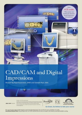
1. Earn
4 CE credits
This course was
written for dentists,
dental hygienists,
and assistants.
CAD/CAM and Digital
Impressions
Written by Paul Feuerstein, DMD and Sameer Puri, DDS
PennWell is an ADA CERP recognized provider
ADA CERP is a service of the American Dental Association to assist dental professionals in identifying
quality providers of continuing dental education. ADA CERP does not approve or endorse individual
courses or instructors, nor does it imply an ADA CERP Recognized Provider
PennWell is acceptance of credit hours by boards of dentistry.
Concerns of complaints about a CE provider may be directed to the provider or to ADA CERP at
www.ada.org/goto/cerp.
Go Green, Go Online to take your course
This course has been made possible through an unrestricted educational grant. The cost of this CE course is $59.00 for 4 CE credits.
Cancellation/Refund Policy: Any participant who is not 100% satisfied with this course can request a full refund by contacting PennWell in writing.
2. An Overview of CAD/CAM and Digital Impressions
by Paul Feuerstein, DMD
Educational Objectives
The overall goal of this section of this two-part course is to
provide the clinician with information on CAD/CAM systems and the potential benefits of the various systems.
Upon completion of this section, the clinician will be
able to do the following:
1. Describe the types of CAD/CAM systems available.
2. Describe the clinical applications and benefits of
current CAD/CAM technology.
touches the tooth to give an optimal focal length; this
system does not require the use of powder. The LAVA
Chairside Oral Scanner (LAVA COS, 3M ESPE) takes a
completely different approach using a continuous video
stream of the teeth.
CEREC and LAVA currently require the use of powder
for the cameras to register the topography. Other scanner
systems are also available.
Figure 1. CAD/CAM systems
Abstract
Currently, two genres of CAD/CAM systems exist. One is
used only in-office, while the other genre is a combination
of in-office scanning and image transmission and milling
of restorations or pouring of models in the laboratory. All
systems start with scanning of the preparation, the method
depending on the specific system.
CAD/CAM systems have developed considerably, offering accuracy and more options than previously. It can be
envisioned that CAD/CAM technology developments will
continue to offer dentistry more options for its use, including
further CAD/CAM integration of procedures and imaging
enhancements.
Introduction
There are two current genres of in-office CAD systems.
One genre is a complete system where the practitioner can
scan preparations, design restorations and manufacture a
finished product in the office, in one visit. The other system
concentrates on the scanning/digital impression and the
practitioner then exports that information to a traditional
dental lab or to a designated CAD/CAM laboratory for
restoration or substructure fabrication. Both genres offer
benefits compared to traditional methods and a number of
systems are available for the practitioner to choose from,
each using different technology to achieve the end results.1,2
Each system uses a system-specific handheld device to scan
the site (Figure 2).
Figure 2. CEREC (upper image) and LAVA COS (lower image)
Image Acquisition
Each system uses a different method to acquire the images.
The first system introduced was the CEREC 1 in 1986. The
CEREC 1, 2 (1994) and 3 (2000) systems (Sirona Dental)
have all used a still camera to take multiple pictures that are
stitched together with software. The E4D (D4D TECH)
takes several images, using a red light laser to reflect off of
the tooth structure and only requires the use of powder in
some limited circumstances. The application of powder to
the tooth is quick and simple, taking only seconds, and the
powder is easily removed afterwards with air and water.
The iTero system uses a camera that takes several views
(stills), and uses a strobe effect as well as a small probe that
2
www.ineedce.com
3. Image Retention/Transmission
Following image acquisition, the final image is either
stored in the system and used for chairside fabrication or digitally transmitted to a laboratory for use. CEREC is a complete
system that allows the restoration to be made chairside and
until the introduction of the E4D system was the only CAD/
CAM system achieving this. All other systems discussed
are used with an indirect method and are digital impression
systems rather than full CAD/CAM systems.
The form that digital transmission takes for the indirect
CAD/CAM methods depends on the system used. CEREC
Connect is used to export the final digital image directly to a
laboratory, where the lab can mill, polish, stain and glaze these
restorations to a level that is sometimes not practical in the
dental office, using a CEREC inLab milling unit (Figure 3).
The LAVA system enables transmission of the data directly
to the LAVA lab machine (Figure 5 ) for a coping that can then
be placed on the acrylic model for the porcelain or other material
to be added; LAVA can be used to print via stereolithography
(SLT) physical models. Alternatively, the digital impression
can be sent to a laboratory for any CAD/CAM or traditional
restoration fabrication. A chairside system is being developed
that will scan a traditional impression in the office and create a
digital impression file (3Shape).
Figure 5. LAVA COS image
Figure 3. CEREC Connect
Depending on the system, the lab can create a physical
model and fabricate restorations traditionally from any material, or design and fabricate restorations using CAD/CAM.
The iTero system offers two options – transmission of
the digital image to an iTero laboratory where a model is
milled using the image and can then be used in a traditional
manner to create the restoration in CAD/CAM and nonCAD/CAM laboratories alike, thereby transforming the
software image into a physical model; alternatively, the digital image can be used to create the restoration using CAD/
CAM (Figure 4).
Figure 4. iTero image
www.ineedce.com
Each unit has its own method of determining centric. The
LAVA COS and iTero have the ability to capture a bite from
the buccal with the patient closed in total contact and occlusion.
There is no wax or impression material between the teeth and
the practitioner can guide and easily see if the patient is closed
correctly. The software simply matches up the upper and lower
scans and places them in centric. The clinician can then see this
bite from all angles on the screen, including from the lingual,
and can also look through the upper to the lower occlusal planes
to examine points of contact (Figure 6). iTero has a feature that
tells the clinician (on the screen as well as actually “talking”) if
there is enough occlusal clearance for the planned restoration.
The CEREC 3D (2003) software currently available allows
you to see the preparation and restoration from all angles and
also has a built-in occlusal feature. After the virtual restoration
has been seated on the digital impression, the occlusal contacts
are visualized using virtual articulation paper. This process
ensures that minimal chairside adjustments are necessary once
the restoration has been seated.
An adjunct technology recently added to the available
systems is Haptic technology (Sensable Technologies). This
is a virtual waxup system whereby the technician can sit in
front of a computer screen looking at a 3D model, and holding
a computerized wax spatula (actually an elaborate computer
mouse) place wax on dies, and even create partial frameworks,
retention bars and other devices with a tactile feedback that
feels like the operator is touching a model. These waxups can
then be created by a CAD/CAM system. Haptic technology
is also being applied for virtual cavity preparation for endodontic procedures.3
3
4. Figure 6. Imaging of occlusion
and proper contacts matching the accuracy of the impression.
Using the in-office CAD/CAM systems, the restoration is
precisely milled to the information given by the software and
the images on the screen. There is of course room for operator
error if the practitioner modifies either of these two parameters outside of the recommendations; however the newest
software versions give a very clear alert. Less time is also required for occlusal adjustments of the final restoration, even
although while centric occlusion is accurately recorded using
scanners lateral excursions may not be digitally perfect.
Table 1. Digital impression and CAD/CAM systems
Full-arch digital
impressions
indicated
Powdering
required
Acquisition
Technology
In-Office Milling
Connectivity to
Labs
Restoration Design
(CAD) Software
Indication for
bridges
Benefits of Digital Impression and CAD/CAM
Systems
Digital impression and CAD/CAM systems offer a number
of benefits over traditional methods. In the case of a complete
CAD/CAM system used to scan preparations and create
restorations in-office, this eliminates a second visit for the
patient (CEREC, Sirona Dental Systems; E4D, D4D Tech).
With both complete systems and chairside scanning systems,
accuracy benefits exist. CAD/CAM restorations have been
found to have good longevity and a fit meeting accepted clinical parameters. 4,5,6,7 ,8,9
Scanning an image and viewing it on a computer screen
allows the clinician to review the preparation and impression,
and make immediate adjustments to the preparation and/or
retake the impression if necessary, prior to its being sent to
the milling unit or a laboratory. This ensures no calls from
a laboratory that a (physical) impression is defective - no
missing margins, pulls or voids in the impression or steps
between two viscosities used that are errors seen in physical
impressions. This review, as well as seeing a preparation multiple times its normal size on a screen, can result in improved
preparations. It is easier to visualize the details on a screen
in a positive view, as opposed to reading the negative in the
impression tray. A digital impression also means that patients
do not have to have impression material and trays used, saving
them discomfort. CAD/CAM restorations will have margins
4
CEREC
Yes
E4D
No
iTero
Yes
LAVA COS
Yes
Yes
Sometimes
No
Some
Blue
light
LED
Yes
Yes
Red light
laser
Confocal
Blue light
LED Video
Yes
No
No
Yes
No
Yes
Yes
Yes
No
No
Yes
No
Yes
Yes
The digital impression systems that export the impression
data to the laboratories and directly mill restorations offer the
same accuracy as in-office milling. Similarly, Haptic technology ensures accuracy for frameworks and metal substructures
as there is no possibility of casting or soldering errors. Other
systems offering similar milling benefits for substructures,
copings and abutments include Procera (Nobel Biocare) and
Atlantis (Astra Tech). The Atlantis system scans the implant
fixture level (traditional) impressions and creates implant
abutments via CAD/CAM that are accurate and time-saving.
At the same time, ‘hardware’ companies have incorporated
features that will make CAD/CAM scanning easier, such as
embossed patterns on healing caps (3i) to make it possible to
accurately scan these for CAD/CAM systems. Scanning at
this level removes the need for transfer abutments and traditional impressions.
For CAD/CAM systems creating a laboratory model,
the model that the technician will work with is different to a
traditional model. Using CAD/CAM technology, the model
is milled or created with stereolithography by a computercontrolled system. The tolerances are in the microns making
these models extremely accurate. The models are also manufactured in a very hard acrylic material, very different to stone
– the hard acrylic margins do not chip away, and contacts are
not worn away as the wax or ceramic are taken on and off of
the model many times while the restoration is created. Dies
www.ineedce.com
5. are cut and trimmed by the laboratory computer and set up
almost like a jig-saw puzzle with interlocking pieces, and
cannot shift during manipulation. This is a great advantage
over saw-cut plaster dies, even if they are held in a special
matrix. CAD/CAM dies do not “wiggle”.
Table 2. Potential benefits of CAD/CAM systems
Accuracy of impressions
Opportunity to view, adjust and rescan impressions
No physical impression for patient
Saves time and one visit for in-office systems
Opportunity to view occlusion
Accurate restorations created on digital models
Potential for cost-sharing of machines
Accurate, wear- and chip-resistant physical CAD/CAM
derived models
No layering/baking errors
No casting/soldering errors
Cost-effective
Cross-infection control
CAD/CAM systems can save time, and after consideration
of the financial investment, they are cost-effective. The advent of accurate scanning, transmission and fabrication of
laboratory CAD/CAM restorations offers an opportunity to,
in effect, cost share on the required equipment. Last but not
least, CAD/CAM also aids cross-infection control.10
The Future
CAD/CAM systems have not completely replaced traditional
impression taking. Undercuts would preclude the digital acquisition, and there are instances where it is difficult for scanners to read the image (e.g., preparations with long subgingival
margins or bevels). It is possible in the future that abutment
and implant scans will be combined, as well as other ‘combination impressions scans’ where frameworks and other appliances
are currently pulled in the impression material. Orthodontic
impressions are on the horizon, and there have been reports
that full arch impressions are being created for fixed appliances
with great success. A combined 3D CBCT radiography and
CAD/CAM system can also be envisioned (such as CEREC
and Galileos). Finally, it can be anticipated that software developments and refinements will continue in the areas of scanning
and imaging of preparations and laboratory in-process images
during the creation of restorations.
Summary
CAD/CAM technology currently includes a number of
systems that fall into two basic genres – in-office and laboratory fabrication of restorations after digital scanning of images. CAD/CAM has been found to be accurate and offer a
number of benefits over traditional in-office and laboratory
techniques. It can be anticipated that CAD/CAM technology in dentistry will continue to develop.
www.ineedce.com
References
1
Beuer F, Schweiger J, Edelhoff D. Digital dentistry: an overview of
recent developments for CAD/CAM generated restorations. Br
Dent J. 2008 May 10;204(9):505-11.
2 Henkel GL. A comparison of fixed prostheses generated from
conventional vs digitally scanned dental impressions. Comp Cont
Ed Dent. Aug 2007;28(8):422-31.
3 Marras I, Nikolaidis N, Mikrogeorgis G, Lyroudia K, Pitas I. A
virtual system for cavity preparation in endodontics. J Dent Educ.
2008 Apr;72(4):494-502.
4
Freedman M, Quinn F, O’Sullivan M. Single unit CAD/
CAM restorations: a literature review. J Ir Dent Assoc. 2007
Spring;53(1):38-45.
5
Raigrodski AJ. Contemporary materials and technologies for allceramic fixed partial dentures: a review of the literature. J Prosthet
Dent. 2004 Dec;92(6):557-62.
6 Otto T, De Nisco S. Computer-aided direct ceramic restorations: a
10-year prospective clinical study of Cerec CAD/CAM inlays and
onlays. Int J Prosthodont. 2002 Mar-Apr;15(2):122-8.
7 Fasbinder DJ. Clinical performance of chairside CAD/CAM
restorations. J Am Dent Assoc. 2006 Sep;137 Suppl:22S-31S.
8
Tinschert J, Natt G, Mautsch W, Spiekermann H, Anusavice
KJ. Marginal fit of alumina-and zirconia-based fixed partial
dentures produced by a CAD/CAM system. Oper Dent. 2001 JulAug;26(4):367-74.
9 Akbar JH, Petrie CS, Walker MP, Williams K, Eick JD. Marginal
adaptation of Cerec 3 CAD/CAM composite crowns using two
different finish line preparation designs. J Prosthodont. 2006 MayJun;15(3):155-63.
10 Freedman M, Quinn F, O’Sullivan M. Single unit CAD/
CAM restorations: a literature review. J Ir Dent Assoc. 2007
Spring;53(1):38-45.
Author Profile
Dr. Paul Feuerstein received his undergraduate degree at SUNY Stony
Brook where he majored in chemistry,
engineering and music and learned how
to program computers. He received his
dental degree at UNJMD in 1972 and
has a general practice in North Billerica,
MA. He installed one of dentistry’s first
“in-office computers” in 1978 and has been teaching dental
professionals how to use computers since the late 70s. He is
currently the technology editor of Dental Economics and the
high tech writer for the Journal of the Massachusetts Dental
Society as well as a contributing author to several national
dental journals. He is an ADA technology lecturer, speaking
at the annual sessions, several state and local dental association meetings.
Disclaimer
The author of this section is a consultant for several technology companies, including the sponsor or provider of the
unrestricted educational grant for this course.
Reader Feedback
We encourage your comments on this or any PennWell course.
For your convenience, an online feedback form is available at
www.ineedce.com.
5
6. Maximizing and Simplifying CAD/CAM Dentistry
by Sameer Puri, DDS
Educational Objectives
The overall goal of this section of this two-part course is to
provide the clinician with information on CAD/CAM in
dentistry and the clinical application of the technology.
Upon completion of this course, the clinician will be able
to do the following:
1. Describe the development of CAD/CAM.
2. Know the clinical applications and results achievable
using current CAD/CAM technology.
Abstract
CAD/CAM has been integrated into dentistry since the
1980s. It offers the clinician the ability to offer patients fixed
restorations of all types. CAD/CAM technology has become
easier to use for the clinician as well as more precise, and offers technological advances over earlier versions.
Introduction
CAD/CAM has been an integral part of our world in many
aspects since its early beginnings in the 1950s.1 From automotive and other industrial uses to the manufacture of products
in all shapes and sizes, CAD/CAM allows us to fabricate
items in an accurate and efficient manner. It is no surprise,
then, that CAD/CAM has become an integral part of an
increasing number of dental offices. From their rudimentary
beginnings, the CAD/CAM systems of today can fabricate
a multitude of restorations including inlays, onlays, veneers,
full crowns and bridges. The restorations are fabricated from
a number of materials including resin, porcelain and acrylic
using prefabricated milling blocks of the chosen material.
For many years, the only dental CAD/CAM system available was the CEREC system, and until the recent introduction of E4D it was also the only fully integrated chairside
CAD/CAM system. Given these facts, much of the clinical
data supporting the accuracy of dental CAD/CAM and the
longevity of CAD/CAM restorations has been based on this
system.
Dental CAD/CAM Development
The first CAD/CAM system for the dental office was
CEREC 1. The system was developed by Prof. Dr. Werner
Moermann in Switzerland and was eventually licensed to
what today is Sirona Dental Systems. For early users, learning to use this machine was difficult and the results were
frustrating. Early adopters who utilized the CEREC 1 had to
have perseverance to get through the learning curve as well as
patience to master the system.
The CEREC 1 was an integrated acquisition and milling
unit that was moved from operatory to operatory. The teeth
were powdered with an opaquing medium and images were
taken with the camera. The DOS-based system allowed
the user to fabricate simple restorations by utilizing a two6
dimensional representation of a three-dimensional object.
As a result of the early technology, these restorations had a
relatively wide marginal gap compared to the current systems.
Nonetheless, despite this gap, the restorations enjoyed a good
success rate due to the strength of the porcelain used and the
hybrid composite that was used to cement the restorations,
thereby bridging the marginal gaps. Under in vitro conditions, composite-luting adaptation to porcelain, glass-ceramic
and composite (assessed using scanning electron microscopy)
has been found to be 100% with CAD/CAM restorations.2
Under in vivo conditions in 1991, Bronwasser et al. found
marginal adaptation of occlusal margins of CEREC inlays to
be 93.6% when used with a dentin adhesive and liner.3 This
was both an earlier version of the CEREC than is currently in
use as well as an earlier generation of adhesive bonding agent;
one early study comparing indirect (CEREC) inlays with
direct inlays using three different ceramic materials found all
to be clinically acceptable after one year.4
The CEREC 2 and subsequent CEREC 3 as well as the
eventual 3-D system replaced the original technology. Each
evolution in the imaging technology led to more indications
that the unit could fabricate, as well as a decreased learning
curve as the software evolved. Initial versions could only
fabricate rudimentary inlays. Subsequent versions could
fabricate cusp replacement onlays, full coverage crowns
and veneers. Laboratory versions developed the ability to
fabricate all types of restorations including frameworks for
bridges. Accuracy and fit also improved from the earliest
versions.5 One study found that CEREC 2 offered a 30%
improvement in the luting interface fit of ceramic inlays
compared to CEREC 1 inlays, and more than two times the
grinding accuracy.6 Schug and colleagues compared CEREC
1 and CEREC 2 inlays and found significant decreases in the
luting interface gap using the more advanced technology (56
+/– 27 microns compared to 84 +/– 38 microns), as well as
significant reductions in cervical line angles.7 Simultaneously,
luting cements developed offering more reliable cements and
more choice for the clinician. While camera angulation using a CEREC 2 could be a concern, one study found that the
average camera angulation error by clinicians was just under
two degrees, insufficient to introduce error as the camera
was tolerant of errors up to five degrees in buccolingual and
mesiodistal planes.8
Clinical Accuracy
Numerous studies have found CAD/CAM restorations
to offer clinical accuracy and precision. Reiss et al. studied
1,010 full-ceramic CEREC crowns between nine and twelve
years after placement, finding a 92% success rate (81 failures)
over this time span.9 A second long-term study of CEREC
inlays and onlays found a 95% likelihood of survival at nine
years. 10 A long-term study on CAD/CAM veneers found
www.ineedce.com
7. that 92% of 617 veneers placed between 1989 and 1997 were
clinically acceptable.11 CEREC 3 software was considerably
more advanced than its predecessor, making the in-office
procedure simpler. Both CEREC 2 and 3 restorations were
found to meet American Dental Association acceptable parameters. 12 In a one-year study of 20 crowns milled chairside
using CEREC 3, Otto found all clinically acceptable at oneyear follow-up with no fractures or loss of retention.13 Following its original introduction, CEREC 3 offered several
technology advances, including streamlining of the graphics
interface, an occlusal-surface design based on biogenerics
(the patient’s existing dental structures) and the ability to
preset the desired luting gap dimensions.14,15
Latest Developments
of light than earlier systems. This results in increased precision. Unlike previous generations of scanners, which took
one image at a time, the Bluecam is a “continuously on”
camera that once you turn it on with a click of the mouse,
it stays on, snapping images automatically as soon as the
camera is held still over a patient’s tooth. This allows the
clinician to take a quadrant of images in as little as a few
seconds. All the user has to do is simply place the camera
over the tooth, move the camera to the desired area to
be captured and hold the camera still. Once the image is
captured, the camera is moved to the next tooth and the
subsequent images are captured to create a virtual model
of the restoration.
The clinical case below shows the use of CEREC AC.
The most current version of the CEREC system is the new
CEREC AC, a modular unit that contains an acquisition unit
(Figure 1) and was introduced in January 2009. A separate
milling unit (Figure 2) has evolved to allow it to fabricate
virtually any type of individual restoration with ease and
precision unmatched by its predecessors.
Clinical Case:
Figure 1. Bluecam scanner
Figure 3. Recurrent decay
The patient presented to the office for an examination.
Initial examination revealed the patient had dental reconstruction done approximately seven years ago. The radiographic examination revealed recurrent decay on teeth #18
and #19 (Figure 3).
Figure 2. CEREC AC unit
The patient was anesthetized with one carpule of septocaine
and the existing crowns were removed. The preparations
were refined and cord was placed to allow for retraction of the
gingival tissues (Figure 4).
Figure 4. Preparation completed, gingival tissue retracted
The main feature of the new system is the camera, which is
referred to as the “Bluecam” and uses the blue spectrum of
visible light and is the most accurate version fabricated. Bluecam uses blue-light light emitting diodes (LEDs) to create
highly detailed digital impressions using shorter wavelengths
www.ineedce.com
Digital impressions were taken with the CEREC AC and
used to fabricate a digital mode. As the preoperative contours
of the teeth to be replaced were close to ideal, the contours of
the teeth were copied by taking images of the teeth prior to
removing the existing crowns.
7
8. Figure 5. Scanned preparation
Contours, occlusion and contacts can all be modified on the
initial proposal.
Figure 8. Proposed restoration
Once all the information had been captured, the software
created a digital impression (Figure 6). The optical quality
results in a detailed and complete model of the patient’s
arch. The margins of the prepared teeth are completely visible and ready for margination.
Figure 6. Digital impression
Once the first restoration is designed, it can be sent to the
milling chamber for fabrication from a variety of materials.
Utilizing the software, the designed restoration can be “virtually seated” on the model and the process can be repeated
for the second restoration (Figures 9, 10). By leveraging your
milling time with your design time, the second restoration can
be designed while the initial is milling. Milling time for each
restoration ranges from 5 to 15 minutes for a molar restoration.
Either a Compact or MC XL milling unit can be used.
Figure 9. First restoration virtually seated on the model
Utilizing the automatic margin finder, the margins of the
preparation were marked and the model was ready to fabricate the initial restoration (Figure 7).
Figure 7. Margins of preparation marked
Figure 10. Second restoration virually seated on the model
The initial proposal was created by the computer, which
resulted in an exact copy of the preoperative situation
(Figure 8). The model can be rotated in all angles and the
restoration contours can be evaluated from different angles.
8
www.ineedce.com
9. After milling, the restorations are esthetically enhanced
and prepared for bonding. A stain and glaze process is completed and appropriate colored stains are utilized to give the
restoration depth and final esthetics (Figure 11).
Figure 11. Final esthetic restorations
5
6
7
8
9
10
11
The restorations are definitively bonded to the teeth, the occlusion is verified and adjusted as needed, and the patient is
dismissed (Figure 12).
Figure 12. Final bonded restorations
12
13
14
15
Sturdevant JR, Bayne SC, Heymann HO. Margin gap size
of ceramic inlays using second-generation CAD/CAM
equipment. J Esthet Dent. 1999;11(4):206-14.
Mörmann WH, Schug J. Grinding precision and accuracy
of fit of CEREC 2 CAD-CIM inlays. J Am Dent Assoc. 1997
Jan;128(1):47-53.
Schug J, Pfeiffer J, Sener B, Mörmann WH. Grinding
precision and accuracy of the fit of CEREC-2 CAD/CIM
inlays. Schweiz Monatsschr Zahnmed. 1995;105(7):913-9.
Parsell DE, Anderson BC, Livingston HM, Rudd JI,
Tankersley JD. Effect of camera angulation on adaptation of
CAD/CAM restorations. J Esthet Dent. 2000;12(2):78-84.
Reiss B, Walther W. Clinical long-term results and 10-year
Kaplan-Meier analysis of CEREC restorations. Int J Comput
Dent. 2000 Jan;3(1):9-23.
Posselt A, Kerschbaum T. Longevity of 2328 chairside
CEREC inlays and onlays. Int J Comput Dent.
2003;6:231-48
Wiedhahn K, Kerschbaum T, Fasbinder DF. Clinical longterm results with 617 CEREC veneers: a nine-year report.
Int J Comput Dent. 2005;8:233-46.
Estefan D, Dussetschleger F, Agosta C, Reich S. Scanning
electron microscope evaluation of CEREC II and CEREC
III inlays. Gen Dent. 2003:51(5):450-4.
Otto T. Computer-aided direct all-ceramic crowns:
preliminary 1-year results of a prospective clinical study. Int
J Perio Rest Dent. 2004 Oct;24(5):446-55.
Dunn M. Biogeneric and user-friendly: the CEREC
3D software upgrade V3.00. Int J Comput Dent. 2007
Jan;10(1):109-17.
Reich S, Wichmann M. Differences between the CEREC3D software versions 1000 and 1500. Int J Comput Dent.
2004 Jan;7(1):47-60.
Author Profile
Summary
Having been a CAD/CAM user for several years, our office and patients have enjoyed the benefits of one-visit dentistry. Patients appreciate the convenience of no provisional
restorations and not having a second visit for the definitive
restoration. The latest technology results in highly accurate
restorations that will allow users to have a minimal learning
curve and fabricate restorations with ease.
References
1
The history of CAD. Available at: http://mbinfo.mbdesign.
net/CAD1960.htm. Accessed December 9, 2008.
2
Hürzeler M, Zimmermann E, Mörmann WH. The
marginal adaptation of mechanically produced onlays in
vitro. Schweiz Monatsschr Zahnmed. 1990;100(6):715-20.
3 Bronwasser PJ, Mörmann WH, Krejci I, Lutz F. The
marginal adaptation of CEREC-Dicor-MGC restorations
with dentin adhesives. Schweiz Monatsschr Zahnmed.
1991;101(2):162-9.
4 Thordrup M, Isidor F, Hörsted-Bindslev P. A one-year
clinical study of indirect and direct composite and ceramic
inlays. Scand J Dent Res. 1994 Jun;102(3):186-92.
www.ineedce.com
Dr. Sameer Puri is a graduate of the
USC School of Dentistry and cofounder of the CEREC training website
www.cerecdoctors.com. He practices
esthetic and reconstructive dentistry
full time in Tarzana, California. Dr.
Puri is also the Director of CAD/CAM
at the Scottsdale Center for Dentistry
where he leads the CEREC training curriculum. He serves
as a consultant to various manufacturers where he helps
develop techniques and materials for dentistry. Dr. Puri is
married and has two children.
Disclaimer
The author of this section is a consultant for the sponsor
or provider of the unrestricted educational grant for this
course.
Reader Feedback
We encourage your comments on this or any PennWell course.
For your convenience, an online feedback form is available at
www.ineedce.com.
9
10. Questions
1. Each system uses a different method to
_________.
a.
b.
c.
d.
prepare the tooth
acquire the model
acquire the images
all of the above
2. There are two current genres of in-office
CAD systems.
a. True
b. False
3. All digital impression systems require the
use of powder.
a. True
b. False
4. The _________ system uses a camera
that takes several views (stills), and uses a
strobe effect as well as a small probe.
a.
b.
c.
d.
CEREC 1
LAVA COS
iTero
all of the above
5. The _________ system uses a continuous
video stream of the teeth.
a.
b.
c.
d.
iTero
CEREC
LAVA Chairside Oral Scanner
none of the above
6. Each system uses a system-specific
handheld device to scan the site.
a. True
b. False
7. Laboratories can only create restorations
from digital impressions if they have
CAD/CAM units.
a. True
b. False
8. It is possible to fabricate _________ using
CAD/CAM systems.
a.
b.
c.
d.
only crowns
crowns, bridges, inlay, veneers and onlays
substructures and copings
b and c
9. Some CAD/CAM systems are able to capture a bite from the buccal with the patient
closed in total contact and occlusion.
a. True
b. False
10. An option to visualize the occlusion
includes _________
a. using virtual articulation paper
b. viewing the bite from all angles on the screen and
looking through the upper to the lower occlusal
planes to examine points of contact
c. milling the wax bite
d. a and b
11. A virtual waxup system can be used for
the _________.
a.
b.
c.
d.
10
creation of dies
creation of partial frameworks
creation of porcelain
a and b
12. A complete CAD/CAM system
eliminates a second visit for the patient.
a. True
b. False
13. Scanning an image and viewing it on
a computer screen allows the clinician
to_________.
a.
b.
c.
d.
review the preparation and impression
make immediate adjustments to the preparation
retake the impression if necessary
all of the above
14. Less time is required for occlusal adjustments of the final restoration using the
newest software versions.
a. True
b. False
15. It is easier to visualize the details on
a screen in a _________, as opposed to
reading the _________.
a.
b.
c.
d.
positive view; negative in the impression tray
negative view; positive in the impression tray
negative view; neutral in the impression tray
none of the above
16. There is no room for operator error
using CAD/CAM systems.
a. True
b. False
17. All CAD/CAM systems are indicated
for bridges.
a. True
b. False
18. Digital impression systems that export
the impression data to the laboratories
and directly milling restorations offer the
same accuracy as in-office milling.
a. True
b. False
19. The use of CAD/CAM systems
_________.
a.
b.
c.
d.
saves time
aids in cross-infection control
removes the possibility of layering and baking errors
all of the above
20. It is possible in the future that abutment
and implant scans will be combined.
a. True
b. False
21. CAD/CAM restorations can be
fabricated from _________.
a.
b.
c.
d.
acrylic
resin
porcelain
all of the above
22. Reiss et al. found a _________success rate
for CAD/CAM crowns.
a.
b.
c.
d.
82%
87%
92%
97%
23. CAD/CAM restorations have been
found to meet American Dental Association acceptable parameters.
a. True
b. False
24. A new scanner uses blue-light light
emitting diodes (LEDs) to create
highly detailed digital impressions
using shorter wavelengths of light than
previously.
a. True
b. False
25. A “continuously on” camera scanner is
available that once you turn it on stays
on and snaps images automatically.
a. True
b. False
26. The milling time for full coverage
CAD/CAM porcelain crowns can range
from __________minutes for a molar
restoration.
a. 5 to 10
b. 5 to 15
c. 10 to 20
d. none of the above
27. Patients appreciate the convenience of
no provisional restorations.
a. True
b. False
28. The first CAD/CAM system for
the dental office was developed by
__________.
a. Prof. Dr. Werner Schmidt
b. Prof. Dr. Werner Moermann
c. Prof. Dr. Ernst Baumgartel
d. none of the above
29. The margins of prepared teeth can be
completely visualized and marginated
using CAD/CAM.
a. True
b. False
30. CAD/CAM technology has become
easier to use as well as more precise, and
offers technological advances over earlier
versions.
a. True
b. False
www.ineedce.com