
Recomendados
Mais conteúdo relacionado
Mais procurados
Mais procurados (20)
Destaque
Destaque (18)
Semelhante a Mnre spec 2013_14
Semelhante a Mnre spec 2013_14 (20)
Último
Último (20)
Mnre spec 2013_14
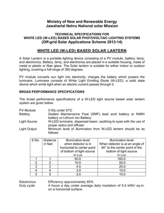
- 1. Ministry of New and Renewable Energy Jawaharlal Nehru National solar Mission TECHNICAL SPECIFICATIONS FOR WHITE LED (W-LED) BASED SOLAR PHOTOVOLTAIC LIGHTING SYSTEMS (Off-grid Solar Applications Scheme 2013-14) WHITE LED (W-LED) BASED SOLAR LANTERN A Solar Lantern is a portable lighting device consisting of a PV module, battery, lamp, and electronics. Battery, lamp, and electronics are placed in a suitable housing, made of metal or plastic or fiber glass. The Solar lantern is suitable for either indoor or outdoor lighting, covering a full range of 360 degrees. PV module converts sun light into electricity, charges the battery which powers the luminaire. Luminaire consists of White Light Emitting Diode (W-LED), a solid state device which emits light when an electric current passes through it. BROAD PERFORMANCE SPECIFICATIONS The broad performance specifications of a W-LED light source based solar lantern system are given below: PV Module 5 Wp under STC Battery Sealed Maintenance Free (SMF) lead acid battery or NiMH battery or Lithium Ion Battery Light Source W-LED luminaire, dispersed beam, soothing to eyes with the use of proper optics and diffuser Light Output Minimum level of illumination from W-LED lantern should be as follows: S No. Distance in feet Illumination level when detector is in horizontal to center point of bottom of light source in Lux Illumination level When detector is at an angle of 90° to the center point of the bottom of light source in Lux 1 1 50.0 160.0 2 2 10.0 50.0 3 3 4.5 25.0 4 4 3.0 15.0 5 5 2.0 10.0 Electronics Efficiency approximately 85% Duty cycle 4 hours a day under average daily insolation of 5.5 kWh/ sq.m. on a horizontal surface.
- 2. Autonomy Minimum of 3 days or 12 operating hours per permissible discharge TECHNICAL DETAILS PV MODULE (i) Indigenously manufactured PV modules should be used in the solar lantern. (ii) The PV module should have crystalline silicon solar cells, and should have humidity, freeze and damp heat tests certificate conforming to IEC 61215 Edition II / BIS 14286 from an NABL or IECQ accredited Laboratory. (iii) The PV module must have a minimum of 5 Wp at a load voltage* of 16.40 V for 12 volt battery or appropriate voltage for charging of battery used, under the standard test conditions (STC) of measurement. (iv) The module efficiency should not be less than 10%. (v) The terminal box on the module should have a provision of opening it for replacing the cable, if required. (vi) There should preferably be an arrangement (stand) for mounting the module at an optimum angle in the direction facing the sun. (vii) A foil/ strip containing the following details should be fixed inside the module so as to be clearly visible from the front side:- a) Name of the Manufacturer and/ or distinctive Logo b) Model and/ or Type No. c) Serial No. d) Year of manufacture (vii) A distinctive serial number starting with NSM will be engraved on the frame of the module or screen printed on the tedlar sheet of the module. *The load conditions of the PV module are not applicable for the system having MPPT. BATTERY (i) Sealed maintenance free lead acid battery with a capacity of up to 7 AH, at voltages of up to 12V @ C/20 rate of discharge or NiMH or Lithium Ion battery of requisite capacity (ii) Battery should conform to the latest BIS/ International standards. LIGHT SOURCE i. The light source will be of White Light Emitting Diode (W-LED) type. ii. The colour temperature of W-LED(s) used in the system should be in the range of 5500o K –6500o K. iii. W-LED(s) should not emit ultraviolet light. iv. The light output from the W - LED should be constant throughout the duty cycle. v. The housing should be suitable for indoor as well as outdoor use.
- 3. ELECTRONICS (i) Efficiency of the electronic system should be at least 85%. (ii) Electronics should have temperature compensation for proper charging of the battery throughout the year. (iii) The idle current should be less than 1 mA (iv) The PCB containing the electronics should be capable of solder free installation and replacement. (v) Necessary lengths of wires/ cables, switches suitable for DC use and other protections should be provided. ELECTRONIC PROTECTIONS (i) Adequate protection is to be incorporated for “No Load” condition, e.g. when the lamp is removed and the lantern is switched ON. (ii) The system should have protection against battery overcharge and deep discharge conditions. (iii) The load reconnect should be provided at around 80% of the battery capacity status. (iv) Adequate protection should be provided against battery reverse polarity. (v) A fuse should be provided to protect against short circuit conditions. (vi) Protection for reverse flow of current through the PV module should be provided. (vii) During the charging, lamp cannot be Switched “ON”. INDICATORS The system should have two indicators, green and red. The green indicator should indicate the charging under progress and should glow only when the charging is taking place. It should stop glowing when the battery is fully charged. Red indicator should indicate the battery “Load Cut Off” condition. QUALITY AND WARRANTY (i) The complete Solar Lantern with W-LED will be warranted for five years and the battery must be warranted for a minimum period of Two (2) years. (ii) The Warrantee/ Guarantee Card to be supplied with the Solar Lantern must contain the details of the system supplied. OPERATION and MAINTENANCE MANUAL An Operation, Instruction and Maintenance Manual, in English and the local language, should be provided with the Solar Lantern. The following minimum details must be provided in the Manual:
- 4. Basic principles of Photovoltaics. A small write-up (with a block diagram) on Solar Lanterns - its components, PV module, battery, electronics and luminaire and expected performance. Significance of indicators. Type, Model number, Voltage, capacity of the battery, used in the system. The make, model number, country of origin and technical characteristics (including IESNA LM-80 report) of W-LEDs used in the lighting system. Clear instructions on mounting, operation, regular maintenance and trouble shooting of the Solar Lantern. Instructions on replacement of battery. DO's and DONT's. Name and address of the contact person for repair and maintenance during the warranty.
- 5. WHITE-LED (W-LED) BASED SOLAR HOME LIGHTING SYSTEMS A solar home lighting system (SHS) provides a comfortable level of illumination in one or more rooms of a house. The SHS consists of a PV module, control electronics, battery, and luminaire(s). There are several SHS models featuring one, two, or four luminaires based on White Light Emitting Diode (W-LED). The system could also be used to run a small DC fan or a 12-V DC television along with the W-LED Lamps. PV module converts sunlight into electricity, which powers the luminaire(s). White Light Emitting Diode (W-LED) is a solid state device which emits light when electric current passes through it. BROAD PERFORMANCE SPECIFICATIONS The broad performance specifications of a W-LED light source based solar home lighting system are given below: Module 6-24 Watt peak under STC Battery Lead acid sealed maintenance free, or NiMH or Lithium-Ion, Lead acid tubular flooded or Gel / VRLA Light Source White Light Emitting Diode (W-LED) Light Out put Minimum 15 Lux when measured at the periphery of 2.5 meter diameter from a height of 2.5 meter. At any point within area of 2.5mtr diameter periphery the light level should not be more than three limes of the periphery value. The illumination should be uniform without Dark Bands or abrupt variations and soothing to the eyes. Higher output would be preferred. Mounting of light Wall or ceiling Electronics Min 85 % efficiency Average duty cycle 5 hours a day under average daily insolation of 5.5 kWh/ sq.m. on a horizontal surface. Autonomy 3 days or Minimum 15 operating hours per permissible discharge There are four models of W-LED home lighting systems. The configuration of each model is as follows: Model-I One White LED luminaire PV Module 6 Wp under STC Battery Lead acid Sealed maintenance free, 12V-7 AH @ C/20 or NiMH or Lithium-Ion of requisite capacity
- 6. Model- II Two White LED luminaire PV Module 12 Wp under STC Battery Lead acid Tubular flooded or Gel / VRLA, 12V - 12AH @ C/20 Model –III Two White LED luminaires and one DC fan of wattage up to 10 W PV Module 24 Wp under STC Battery Lead acid Tubular flooded or Gel / VRLA, 12V- 20AH @ C/20 Model –IV Four White LED luminaires PV Module 24 Wp under STC Battery Lead acid Tubular flooded or Gel / VRLA, 12V- 20AH @ C/20 It should have a socket to provide power for a 12V DC TV set which can be purchased separately. TECHNICAL DETAILS PV MODULE (S) i. Indigenously manufactured PV modules should be used ii. The PV modules up to 12 Wp capacity should have crystalline silicon solar cells, and should have humidity, freeze and damp heat tests certificate conforming to IEC 61215 Edition II / BIS 14286 from an NABL or IECQ accredited Laboratory. iii. The PV modules more than 12 Wp capacity should be made up of crystalline silicon solar cells and must have a certificate of testing conforming to IEC 61215 Edition II / BIS 14286 from an NABL or IECQ accredited Laboratory. iv. The power output of the module(s) under STC should be a minimum of 6 Wp or 12 Wp or 24 Wp. v. The Load voltage* of 16.40 V for 12 V battery or appropriate voltage for charging of battery used, under the standard test conditions (STC) of measerment. vi. The module efficiency should not be less than 10%. vii. The terminal box on the module should have a provision for opening, for replacing the cable, if required. viii. There should be a Name Plate fixed inside the module which will give: a. Name of the Manufacturer or Distinctive Logo. b. Model Number c. Serial Number d. Year of manufacture ix. A distinctive serial number starting with NSM will be engraved on the frame of the module or screen printed on the tedlar sheet of the module.
- 7. *The Load voltage conditions of the PV modules are not applicable for the system having MPPT. BATTERY (i) For Model-I, sealed maintenance free lead acid battery with a capacity of up to 7 AH, at voltages of up to 12V @ C/20 rate of discharge or NiMH or Lithium Ion battery of requisite capacity. (ii) For Models – II, III & IV, battery should have a minimum rating of 12V, 12 Ah or 12V, 20 Ah at C/20 rate of discharge, depending on the Model. (iii) 75 % of the rated capacity of the battery should be between fully charged & load cut off conditions. (iv) Battery should conform to the latest BIS/ International standards. LIGHT SOURCE (i) The light source will be of white LED type. (ii) The colour temperature of W-LEDs used in the system should be in the range of 5500o K–6500o K. (iii) LEDs should not emit ultraviolet light. (iv) The light output from the W-LED light source should be constant throughout the duty cycle. (v) The lamps should be housed in an assembly suitable for indoor use. ELECTRONICS i. The total electronic efficiency should be at least 85 %. ii. Electronics should have temperature compensation for proper charging of the battery throughout the year. The idle current should be less than 1 mA for Models-I & II, and for Models-III & IV, it should be less than 2mA. iii. The voltage drop from module terminals to the battery terminals should not exceed 0.6 volts including the drop across the diode and the cable when measured at maximum charging current. iv. The PCB containing the electronics should be capable of solder free installation and replacement. v. Necessary lengths of wires/cables, switches suitable for DC use and fuses should be provided. ELECTRONIC PROTECTIONS (i) Adequate protection is to be incorporated under “No Load” condition, e.g. when the lamps are removed and the system is switched ON. (ii) The system should have protection against battery overcharge, deep discharge condition. (iii) Load reconnect should be provided at 80% of the battery capacity status. (iv) Adequate protection should be provided against battery reverse polarity.
- 8. (v) Fuses should be provided to protect against short circuit conditions. (vi) Protection for reverse flow of current through the PV module(s) should be provided. MECHANICAL COMPONENTS (i) Corrosion resistant metallic frame structure should be provided to hold the SPV module. (ii) The frame structure should have provision to adjust its angle of inclination to the horizontal, so that it can be installed at the specified tilt angle. (iii) Light source should be either for wall mounted or ceiling mounted or can be hung from the ceiling in a stable manner, as per site requirements. (iv) A vented plastic/ wooden/ metallic box with acid proof corrosion resistant paint for housing the storage battery indoors should be provided. INDICATORS The system should have two indicators, green and red. The green indicator should indicate the charging under progress and should glow only when the charging is taking place. It should stop glowing when the battery is fully charged. Red indicator should indicate the battery “Load Cut Off” condition QUALITY AND WARRANTY (i) The Solar home lighting system will be warranted for a period of five years from the date of supply. (ii) The PV module(s) will be warranted for a minimum period of 25 years from the date of supply. PV modules used in Solar Home Lighting System must be warranted for their output peak watt capacity, which should not be less than 90% at the end of Ten (10) years and 80% at the end of Twenty five (25) years. (iii) The battery for Model-I should be warranted for a period of at least two years. The batteries for Models–II, III & IV should be warranted for a period of 5 years. (iv) The Warranty Card to be supplied with the system must contain the details of the system. The manufacturers can also provide additional information about the system and conditions of warranty as necessary. OPERATION and MAINTENANCE MANUAL An Operation, Instruction and Maintenance Manual, in English and the local language, should be provided with the Solar Home Lighting System. The following minimum details must be provided in the Manual: Basic principles of Photovoltaics.
- 9. A small write-up (with a block diagram) on Solar Home Lighting System - its components, PV module, battery, electronics and luminaire and expected performance. Significance of indicators. Type, Model number, voltage & capacity of the battery, used in the system. The make, model number, country of origin and technical characteristics (including IESNA LM-80 report) of W-LEDs used in the lighting system must be indicated in the manual. Clear instructions about mounting of PV module(s). Clear instructions on regular maintenance and trouble shooting of the Solar Home Lighting System. DO's and DONT's. Name and address of the contact person for repair and maintenance.
- 10. WHITE-LED (W-LED) BASED SOLAR STREET LIGHTING SYSTEM A stand alone solar photovoltaic street lighting system (SLS) is an outdoor lighting unit used for illuminating a street or an open area. The Solar Street Lighting System consists of solar photovoltaic (SPV) module, a luminaire, storage battery, control electronics, inter-connecting wires/cables, module mounting pole including hardware and battery box. The luminaire is based on White Light Emitting Diode (W-LED), a solid state device which emits light when electric current passes through it. The luminaire is mounted on the pole at a suitable angle to maximize illumination on the ground. The PV module is placed at the top of the pole at an angle facing south so that it receives solar radiation throughout the day, without any shadow falling on it. A battery is placed in a box attached to the pole. Electricity generated by the PV module charges the battery during the day time which powers the luminaire from dusk to dawn. The system lights at dusk and switches off at dawn automatically. BROAD PERFORMANCE SPECIFICATIONS PV Module 40 Wp under STC Battery Lead acid Tubular Flooded or Tubular GEL / VRLA , 12V- 40 AH @ C/10 Light Source White Light Emitting Diode (W-LED) Light Out put Minimum 15 Lux when measured at the periphery of 4 meter diameter from a height of 4 meter. The illumination should be uniform without dark bands or abrupt variations, and soothing to the eye. Higher light output will be preferred. Mounting of light Minimum 4 metre pole mounted Electronics Efficiency Minimum 85% total Duty Cycle Dusk to dawn Autonomy 3 days or Minimum 42 operating hours per permissible discharge TECHNICAL DETAILS PV MODULE (i) Indigenously manufactured PV module should be used. (ii) The PV module should have crystalline silicon solar cells and must have a certificate of testing conforming to IEC 61215 Edition II / BIS 14286 from an NABL or IECQ accredited Laboratory. (iii) The power output of the module(s) under STC should be a minimum of 40 Wp at a load voltage* of 16.4 ± 0.2 V.
- 11. (iv) The open circuit voltage* of the PV modules under STC should be at least 21.0 Volts. (v) The module efficiency should not be less than 12 %. (vi) The terminal box on the module should have a provision for opening it for replacing the cable, if required. (vii) There should be a Name Plate fixed inside the module which will give: a. Name of the Manufacturer or Distinctive Logo. b. Model Number c. Serial Number d. Year of manufacture (viii) A distinctive serial number starting with NSM will be engraved on the frame of the module or screen printed on the tedlar sheet of the module. *The load voltage and Voc conditions of the PV modules are not applicable for the system having MPPT based charge controller BATTERY i. Lead Acid, tubular positive plate flooded electrolyte or Gel / VRLA Type. ii. The battery will have a minimum rating of 12V, 40 Ah at C/10 discharge rate. iii. 75 % of the rated capacity of the battery should be between fully charged and load cut off conditions. iv. Battery should conform to the latest BIS/ International standards. LIGHT SOURCE i. The light source will be a white LED type. ii. The colour temperature of white LED used in the system should be in the range of 5500o K–6500o K. iii. W-LEDs should not emit ultraviolet light. iv. The light output from the white LED light source should be constant throughout the duty cycle. v. The lamps should be housed in an assembly suitable for outdoor use. vi. The temperature of heat sink should not increase more than 20o C above ambient temperature during the dusk to dawn operation. ELECTRONICS i. The total electronic efficiency should be at least 85%. ii. Electronics should operate at 12 V and should have temperature compensation for proper charging of the battery throughout the year. iii. No Load current consumption should be less than 20 mA. iv. The PV module itself should be used to sense the ambient light level for switching ON and OFF the lamp.
- 12. v. The PCB containing the electronics should be capable of solder free installation and replacement. vi. Necessary lengths of wires/cables, switches suitable for DC use and fuses should be provided. ELECTRONIC PROTECTIONS i. Adequate protection is to be incorporated under “No Load” conditions e.g. when the lamp is removed and the system is switched ON. ii. The system should have protection against battery overcharge and deep discharge conditions. iii. Fuse should be provided to protect against short circuit conditions. iv. Protection for reverse flow of current through the PV module(s) should be provided. v. Electronics should have temperature compensation for proper charging of the battery throughout the year. vi. Adequate protection should be provided against battery reverse polarity. vii. Load reconnect should be provided at 80% of the battery capacity status. MECHANICAL COMPONENTS i. A corrosion resistant metallic frame structure should be fixed on the pole to hold the SPV module. ii. The frame structure should have provision to adjust its angle of inclination to the horizontal between 0 and 45, so that the module can be oriented at the specified tilt angle. iii. The pole should be made of Galvanised Iron (GI) pipe. iv. The height of the pole should be 4 metres above the ground level, after grouting and final installation. v. The pole should have the provision to hold the luminaire. vi. The lamp housing should be water proof and should be painted with a corrosion resistant paint. vii. A vented, acid proof and corrosion resistant metallic box with a locking arrangement for outdoor use should be provided for housing the battery. INDICATORS The system should have two indicators, green and red. The green indicator should indicate the charging under progress and should glow only when the charging is taking place. It should stop glowing when the battery is fully charged. Red indicator should indicate the battery “Load Cut Off” condition. QUALITY AND WARRANTY i. The street lighting system (including the battery) will be warranted for a period of five years from the date of supply.
- 13. ii. The PV module(s) will be warranted for a minimum period of 25 years from the date of supply. The PV modules must be warranted for their output peak watt capacity, which should not be less than 90% at the end of Ten (10) years and 80% at the end of Twenty five (25) years. iii. The Warranty Card to be supplied with the system must contain the details of the system. OPERATION and MAINTENANCE MANUAL An Operation, Instruction and Maintenance Manual, in English and the local language, should be provided with the Solar Street Lighting System. The following minimum details must be provided in the Manual: Basic principles of Photovoltaics. A small write-up (with a block diagram) on Solar Street Lighting System - its components, PV module, battery, electronics and luminaire and expected performance. Type, Model number, Voltage & capacity of the battery, used in the system. The make, model number, country of origin and technical characteristics (including IESNA LM-80 report) of W-LEDs used in the lighting system. About Charging and Significance of indicators. Clear instructions about erection of pole and mounting of PV module (s) and lamp housing assembly on the pole. Clear instructions on regular maintenance and trouble shooting of the Solar Street Lighting System. DO's and DONT's. Name and address of the contact person for repair and maintenance, in case of non-functionality of the solar street lighting system.