Modelling and simulation of SAS system with MR damper Dimuthu Dharshana
•Transferir como PPTX, PDF•
1 gostou•2,309 visualizações

MAS417 Mathematics for Mechatronics- Spring 2013, University of Agder, Grimstad, Norway

Recomendados
Recomendados
Mais conteúdo relacionado
Destaque
Destaque (19)
Semelhante a Modelling and simulation of SAS system with MR damper Dimuthu Dharshana
Semelhante a Modelling and simulation of SAS system with MR damper Dimuthu Dharshana (20)
Último
Último (20)
Modelling and simulation of SAS system with MR damper Dimuthu Dharshana
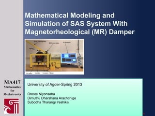
- 1. Mathematical Modeling and Simulation of SAS System With Magnetorheological (MR) Damper MA417 Mathematics for Mechatronics University of Agder-Spring 2013 Oreste Niyonsaba Dimuthu Dharshana Arachchige Subodha Tharangi Ireshika Slide 1
- 2. Overview • • • • • • • Vibration isolation MR dampers and SAS test rig Mathematical modeling and stability MR damper models Vibration response analysis Experimental comparison Conclusion Slide 2
- 3. Vibration Isolation • In most mechanical systems the excess energy that is created becomes vibration • Vibration leads to • • • • • • excessive wear of bearings formation of cracks loosening of fasteners structural and mechanical failures frequent and costly maintenance of machines discomfort to humans • A vibration isolation system is needed to reduce vibrations Slide 3
- 4. Isolation systems Passive: • No need of external power source • Simple, inexpensive and reliable isolation • Inherent performance limitations Semi-active: • Excellent compromise between passive and active systems • Require low power for signal processing • Improved vibration isolation Active: • Control forces change with excitation and response characteristics • Need of external energy source • Can supply and dissipate energy Slide 4
- 5. Magneto-Rheological (MR Dampers) MR Fluid MR fluid is composed of oil and varying percentages of iron particles that have been coated with an anti-coagulant material Without Magnetic field With Magnetic field Slide 5
- 6. Modes of operation of MR fluid a.Valve mode b.Shear mode c.Squeeze mode Slide 6
- 7. MR Rotary damper and SAS test rig. active MR fluid area output axis magnetic circuit(rotor) magnetic circuit(stator) coil magnetic flux line Viscosity is changed due to the generated magnetic field of the coil, affecting to control the torque of the output axis Semi Active Suspension (SAS) system with MR rotary brake Slide 7
- 8. Mathematical modeling of the SAS system Analysis of the upper beam Analysis of the lower beam Slide 8
- 9. Stability investigation Current input to the MR damper 0A 0.4 2.5 0.3 2 1.5 Alpha2Dot(Rad/s) Alpha1Dot(Rad/s) 0.2 0.1 0 -0.1 1 0.5 0 -0.5 -1 -0.2 -1.5 -0.3 -4 -3 -2 -1 Alpha1(Deg) 0 1 2 -2 20 25 30 35 40 45 Alpha2(Degree) Equilibrium points Slide 9 50
- 10. MR Damper models a. The Bouc-Wen model x Torque (T) generated by the MR damper, θ γ=1, β=737,δ=843, n=1.9, C1=0.0015, C2=17, α1=1,α2=17 [9] Slide 10
- 11. Hysteresis behavior Effect of the control current Torque Vs Angular Displacement Torque Vs Angular Velocity 100 100 i=0 i=1 i=2 i=3 80 60 60 40 20 20 Torque(Nm) 40 Torque(Nm) i=0 i=1 i=2 i=3 80 0 -20 0 -20 -40 -40 -60 -60 -80 -80 -100 0 0.5 1 1.5 Angular Displacement(rad) 2 Current 2.5 -100 -1 -0.8 -0.6 -0.4 -0.2 0 0.2 0.4 Angular Velocity(rad/s) 0.6 Torque Slide 11 0.8 1
- 12. Effect of MR Damper parameters on.. 1. Displacement Hysteresis for 2A Torque Vs Angular Displacement for different gamma values(i=2) Torque Vs Angular Displacement for different delta values(i=2) 60 60 gamma=0.2 gamma=1 gamma=5 gamma=7 40 40 20 Torque(Nm) Torque(Nm) 20 0 0 -20 -20 -40 -40 -60 -0.5 0 0.5 1 1.5 2 Angular Displacement(rad) Torque Vs Angular Displacement for different n values(i=2) -60 -0.5 2.5 0.5 1 1.5 Angular Displacement(rad) 2 2.5 80 n=1 n=1.9 n=5 n=8 60 40 beta=500 beta=600 beta=737 beta=900 60 40 20 Torque(Nm) 20 0 -20 0 -20 -40 -40 -60 -80 -0.5 0 Torque Vs Angular Displacement for different beta values(i=2) 80 Torque(Nm) delta=600 delta=700 delta=843 delta=900 -60 0 0.5 1 1.5 Angular Displacement(rad) 2 2.5 -80 -0.5 0 0.5 1 1.5 Angular Displacement(rad) 2 2.5 Slide 12
- 13. Effect of MR Damper parameters on.. 2. Velocity Hysteresis for 2A Torque Vs Angular Velocity for different gamma values(i=2) Torque Vs Angular Velocity for different beta values(i=2) 60 60 gamma=0.2 gamma=1 gamma=5 gamma=7 40 40 20 20 Torque(Nm) Torque(Nm) delta=600 delta=700 delta=843 delta=900 0 0 -20 -20 -40 -40 -60 -1 -0.8 -0.6 -0.4 -0.2 0 0.2 0.4 Angular Velocity(rad/s) 0.6 0.8 -60 -1 1 -0.8 -0.4 -0.2 0 0.2 0.4 Angular Velocity(rad/s) 0.6 0.8 1 Torque Vs Angular Velocity for different n values(i=2) Torque Vs Angular Velocity for different beta values(i=2) 80 80 beta=500 beta=600 beta=737 beta=900 60 40 n=1 n=1.9 n=5 n=8 60 40 20 Torque(Nm) 20 Torque(Nm) -0.6 0 0 -20 -20 -40 -40 -60 -60 -80 -1 -0.8 -0.6 -0.4 -0.2 0 0.2 0.4 0.6 0.8 1 -80 -1 -0.8 -0.6 -0.4 -0.2 0 0.2 0.4 0.6 0.8 1 Slide 13
- 14. Effect of MR damper parameters on the vibration response Vibration Response Vs Time for different gamma values(i=0.25A) 50 50 gamma=0.2 gamma=1 gamma=7 45 n=1 n=1.9 n=8 45 40 40 30 Vibration(Degrees) 35 35 30 35 30 25 25 25 20 20 20 15 0 0.2 0.4 0.6 0.8 1 1.2 Time(Time) 1.4 1.6 1.8 15 2 15 0 Vibration Response Vs Time for different beta values(i=0.25A) 0.2 0.4 0.6 0.8 1 1.2 Time(Time) 1.4 1.6 1.8 2 beta=500 beta=737 beta=900 0.4 0.6 0.8 1 1.2 Time(Time) 1.4 1.6 1.8 2 Vibration Response Vs Time for different C2 values(i=0.25A) alpha2=12 alpha2=17 alpha2=20 45 c2=6 c2=10.5 c2=20 40 35 30 Vibration(Degrees) 40 Vibration(Degrees) 40 0.2 45 50 45 0 Vibration Response Vs Time for different alpha2 values(i=0.25A) 50 Vibration(Degrees) delta=600 delta=843 delta=900 45 40 Vibration(Degrees) Vibration(Degrees) Vibration Response Vs Time for different delta values(i=0.25A) Vibration Response Vs Time for different n values(i=0.25A) 50 35 30 25 20 30 25 25 20 35 15 0 0.2 0.4 0.6 0.8 1 1.2 Time(S) 1.4 1.6 1.8 2 15 20 15 0 0.2 0.4 0.6 0.8 1 1.2 Time(Time) 1.4 1.6 1.8 2 0 0.2 0.4 0.6 0.8 1 1.2 Time(Time) 1.4 1.6 1.8 Slide 14 2
- 15. Comparison: experiment and computer simulations a. Bouc-Wen Displacement Vs Time(i=.25) Displacement Vs Time(i=1A) 50 45 Theoratical Experimental 40 40 Displacement(Degrees) Displacement(Degrees) 45 Theoratical Experimental 35 30 25 30 25 20 20 15 35 0 5 10 15 Time(s) 20 25 15 0 5 10 15 20 Time(s) Slide 15 25
- 16. Dhal model T z K x (i) K y (i) z ( Kx K a Kb i Ky K1 K 2 i z) T : exerted torque of the MR brake θ : angle i : control current z : dynamic hysteresis coefficient Kx ,Ky, α: parameters which controls the shape of the hysteric. K1 5, K 2 1.5, K a 0.001, K b 0.001, Slide 16 5
- 17. Hysteresis behavior • Effect of the control current Torque Vs Angular Displacement Torque Vs Angular Velocity 8 6 6 4 4 2 2 Torque (Nm) 10 8 Torque (Nm) 10 0 -2 -4 -2 -4 i=0 i=1 i=2 i=3 -6 -8 -10 0 0 0.2 0.4 0.6 0.8 1 1.2 1.4 Angular Displacement (rad) 1.6 1.8 -6 i=0 i=1 i=2 i=3 -8 2 -10 -1 -0.8 -0.6 -0.4 -0.2 0 0.2 0.4 Angular Velocity (rad/s) 0.6 0.8 Slide 17 1
- 18. Effect of MR damper parameters on.. • Displacement hysteresis for 2 A Torque Vs Angular Displacement for different Ka values (i=2) Torque Vs Angular Displacement for different K1 values(i=2) 20 15 15 10 10 Torque (Nm) 5 0 0 -5 -5 -10 K1=0 K1=5 K1=7 K1=10 -10 -15 0 0.2 0.4 0.6 0.8 1 1.2 1.4 Angular Displacement (rad) 1.6 1.8 Ka=0.001 Ka=1 Ka=5 Ka=10 -15 -20 2 0 0.2 0.4 0.6 0.8 1 1.2 1.4 Angular Displacement (rad) 1.6 1.8 2 Torque Vs Angular Displacement for different Alpha values (i=2) 10 8 6 4 Torque (Nm) Torque (Nm) 5 2 0 -2 -4 -6 Alpha=1 Alpha=5 Alpha=10 Alpha=15 -8 -10 -0.5 0 0.5 1 Angular Displacement (rad) 1.5 2 Slide 18
- 19. Effect of MR damper parameters on.. • Velocity hysteresis for 2A Torque Vs Angular Velocity for different Ka values (i=2) Torque Vs Angular Velocity for different K1 values (i=2) 20 15 15 10 10 Torque (Nm) 5 0 0 -5 -5 -10 K1=0 K1=5 K1=7 K1=10 -10 -15 -1 -0.8 -0.6 -0.4 -0.2 0 0.2 0.4 Angular Velocity (rad/s) 0.6 0.8 Ka=0.001 Ka=1 Ka=5 Ka=10 -15 -20 -1 1 -0.8 -0.6 -0.4 -0.2 0 0.2 0.4 Angular Velocity (rad/s) 0.6 0.8 1 Torque Vs Angular Velocity for different Alpha values (i=0) 6 4 2 Torque (Nm) Torque (Nm) 5 0 -2 Alpha=1 Alpha=5 Alpha=10 Alpha=15 -4 -6 -1 -0.8 -0.6 -0.4 -0.2 0 0.2 0.4 Angular Velocity (rad/s) 0.6 0.8 1 Slide 19
- 20. Effect of MR damper parameters on the vibration response Vibration Response Vs Time for different K1 values (i=1) 50 K1=0 K1=5 K1=7 Vibration Response (Degrees)) 45 40 35 30 25 20 Ka=0.001 Ka=0 Ka=10 15 Time (s) 20 25 30 Alpha=0 Alpha=5 Alpha=7 45 Vibration Response (Degrees)) Vibration Response (Degrees)) 10 50 40 35 30 40 35 30 25 25 20 5 Vibration Response Vs Time for different Alpha values (i=1) Vibration Response Vs Time for different Ka values(i=1) 50 45 0 20 0 5 10 15 Time (s) 20 25 30 0 5 10 15 Time (s) 20 25 30 Slide 20
- 21. Experimental task for hysteresis measurement Torque from the MR damper, M MR d 1 dt d 2 dt d2 2 J2 dt 2 M MR d 1 dt d 2 dt d2 2 J2 dt 2 d 2 k2 dt M spring r2 k s los RG2 cos k2 d 2 dt (r2 sin 2 RG2 cos 2 r1 sin 1 2 )2 r1 cos 1 r2 cos 2 Slide 21
- 22. Hysteresis behavior of the MR damper • Displacement Hysteresis Torque Vs Displacement (i=0.25) Torque Vs Displacement (i=1) Torque Vs Displacement (i=1.5) 10 10 0 0 0 -10 -10 -10 -20 Torque (Nm) 20 Torque (Nm) 20 10 Torque (Nm) 20 -20 -20 -30 -30 -30 -40 -40 -40 -50 -50 -50 -60 -0.3 -0.25 -0.2 -0.15 -0.1 -0.05 0 Displacement (rad) 0.05 0.1 0.15 -60 -0.4 0.2 -0.3 -0.2 -0.1 0 Displacement (rad) 0.1 0.2 -60 -0.3 0.3 -0.25 -0.2 -0.15 -0.1 -0.05 0 Displacement (rad) 0.05 0.1 0.15 0.2 2 2.5 • Velocity Hysteresis Torque Vs Velocity (i=1) Torque Vs Velocity (i=0.25) Torque Vs Velocity (i=1.5) 10 10 0 0 0 -10 -10 -10 -20 Torque (Nm) 20 Torque (Nm) 20 10 Torque (Nm) 20 -20 -20 -30 -30 -30 -40 -40 -40 -50 -50 -50 -60 -2 -1.5 -1 -0.5 0 0.5 Velocity (rad/s) 1 1.5 2 -60 -2 -1.5 -1 -0.5 0 0.5 Velocity (rad/s) 1 1.5 2 2.5 -60 -2 -1.5 -1 -0.5 0 0.5 Velocity (rad/s) 1 1.5 Slide 22
- 23. Comparison: experiment and computer simulations b. Dhal Displacement Vs Time(i=0.25) Displacement Vs Time(i=1) 50 50 Theoritical Experiment 45 40 Displacement (Degrees) Displacement (Degrees) 45 35 30 25 20 15 Theoritical Experiment 40 35 30 25 20 0 5 10 15 Time (s) 20 25 15 0 5 10 15 20 Time (s) Slide 23 25
- 24. Conclusion • Easy to analyze MR damper with SAS test rig which supports Matlab Simulink environment. • Both theoretical and experimental models, magnitude of torque in hysteresis behavior lies in a common range. • If model parameters are diligently tuned, a similar vibration response can be obtained for both theoretical and experimental models. • Bouc-Wen model stands taller as far as the more realistic, accurate results are concerned. • Semi-active dampers provide remarkable improvements over passive suspensions. Slide 24