SlideShare uma empresa Scribd logo
1 de 4
Baixar para ler offline
Research-inspired problems for electricity and magnetism
Beth Parksa͒
Physics Department, Colgate University, Hamilton, New York 13346
͑Received 17 August 2005; accepted 16 December 2005͒
I present several problems related to current research problems and techniques that are suitable for
introductory and intermediate electricity and magnetism. © 2006 American Association of Physics Teachers.
͓DOI: 10.1119/1.2166369͔
I. INTRODUCTION
Electricity and magnetism is a well-established field, so it
is difficult to inspire students with problems from current
research topics. One reason that the subject is still an impor-
tant part of the curriculum is the frequency with which we
need to solve basic problems in electricity and magnetism as
part of our research. Incorporating some of these real-life
problems into courses can help motivate students to learn
electricity and magnetism.
In this article I will share several of these problems,
sketches of their solutions, and some background informa-
tion. Some of the problems are suitable for an introductory
course in electricity and magnetism, and others belong in a
second course. I have not included problems for use in an
advanced course because at that level the research applica-
tions are much more numerous.
II. INTERACTIONS BETWEEN ELECTRON SPINS
The magnetic dipole-dipole interaction is almost always
negligible between electrons in solids in comparison to the
much larger magnetic couplings caused by Coulomb ex-
change interactions. However, in the layered material
Sr2Cu3O4Cl2, the symmetry of the crystal lattice completely
frustrates the exchange interactions, and a weak ferromag-
netism is caused by magnetic dipole-dipole interactions.
Figure 1 shows the structure of the Cu3O4 planes. The
black circles are copper ions and the white circles are oxygen
ions. Copper ions have one unpaired electron, giving the ion
a net spin of 1
2. ͑Do not confuse this spin with the nuclear
spin, which produces a much smaller magnetic moment that
is irrelevant to this problem.͒ The spins of the copper ions at
the corners of the squares are strongly antiferromagnetically
coupled to their neighbors and align as shown. ͑This align-
ment is caused by Coulomb exchange interactions, as is the
case for almost every magnetic material.͒ The distance be-
tween the antiferromagnetically coupled spins is a
=0.386 nm. The planes are separated from each other by
0.626 nm. Therefore, the density of the center copper atoms
is one per 0.187 nm3
.
Problem 1. The copper ions at the centers of the squares
͑labeled II͒ interact ferromagnetically with each copper ion
at the corners ͑labeled I͒. ͑Do not confuse the labels I and II
with the charge of the ions, which are all +2.͒ Discuss why
these interactions do not result in magnetic ordering of the
center coppers. ͑Hint: Along what direction would the copper
II spin point due to interactions with each of the corner cop-
per atoms individually?͒
Problem 2. Because the stronger exchange interactions are
ineffective, consider the effect of dipole-dipole interactions.
In what direction does this interaction try to align the spins
on the two copper ͑II͒ sites shown? Consider only interac-
tions with the four nearest neighbors, because all other inter-
actions will be much weaker. It would help to sketch the field
lines due to the four neighbors.
Problem 3. What is the strength of the interaction; that is,
what is the energy difference between the highest and lowest
energy alignments of the electrons at the centers of the
squares? Compare this energy with kBT at 40 K.
Problem 4. What would the magnetization M of the mate-
rial be at 40 K? ͑Just below 40 K, the material undergoes a
phase transition to a different magnetic structure.͒ Recall
from statistical mechanics that if the alignment energy ⌬E is
much less than kBT, the magnetization is reduced from its
maximum value by the ratio ⌬E/6kBT.1
Solutions: Because the ferromagnetic interactions cancel
by symmetry, the remaining interaction is the dipole-dipole
interaction, which tends to orient the spins in these two cen-
ter copper ͑II͒ ions along the −y-direction as defined in Fig.
1. If there were copper ions at the centers of the other two
squares, they would be oriented along the +y-direction, and
no bulk ferromagnetic moment would be measured. How-
ever, because there are copper ions only in the centers of
alternate squares, there is a net ferromagnetic moment. The
alignment energy is E=m·B, where B is the magnetic field
at the center due to the four corner ions. The field due to one
of the corner electrons at the location of the center electron is
B1 =
␮0m
4␲r3͑2 cos ␪rˆ + sin ␪␪ˆ͒, ͑1͒
where r=a/ͱ2 and ␪=␲/4. Only the component of B1 that
lies along the direction of magnetization will contribute; the
other component will cancel with the B-field from another
copper ion. The result for the total B-field from all four ions
is B=3ͱ2␮0m/␲a3
. Therefore the alignment energy is ⌬E
=mup·B−mdown·B=2ϫ3ͱ2m2
␮0/␲a3
=5.1ϫ10−24
J, be-
cause the magnetic moment of an electron is ␮B=9.27
ϫ10−24
J/T ͑gϷ2͒. At 40 K, kBT=5.5ϫ10−22
J, so the ther-
mal energy is much greater than this alignment energy. In
this case, the magnetization will be
M =
nm⌬E
6kBT
=
ͱ2m3
n␮0
kBT␲a3 , ͑2͒
where n is the density of spins, 5.4ϫ1027
m−3
. Equation ͑2͒
gives a magnetization of 77 J/T-m3
.
I have presented only the simplest explanation of the mag-
netic behavior that is consistent with experimental observa-
tions; more complicated possibilities also exist. More infor-
mation about this material can be found in Ref. 2.
351 351Am. J. Phys. 74 ͑4͒, April 2006 http://aapt.org/ajp © 2006 American Association of Physics Teachers
III. SQUID MAGNETOMETER
Measurements of the magnetic moment as a function of
applied field are essential to the characterization of supercon-
ductors, ferromagnets, and antiferromagnets such as
Sr2Cu3O4Cl2. A SQUID magnetometer is one of the most
sensitive ways to measure the magnetic moment of a small
sample. A SQUID ͑superconducting quantum interference
device͒ converts a magnetic flux through its pick-up loop
into a voltage that can be easily measured.
When the sample is held in a magnetic field inside the
magnetometer, the sample develops a dipole moment that
produces a flux through the SQUID pickup loop. A charac-
teristic voltage signal is produced that is proportional to the
flux. ͑This phenomenon is very different from induction in a
normal pickup loop in which the induced voltage is propor-
tional to the rate of change of the flux.͒ The flux through the
loop is a function of the distance of the sample from the
loop, so as the sample is moved through the pickup loop, the
voltage changes as a function of position. The magnetic mo-
ment of the sample is calculated by fitting the observed
variation in the voltage signal to the predicted dipole shape.
Your assignment is to calculate this shape.
Problem 5. The geometry is shown in Fig. 2. Assume that
the pick-up loop is 2.5 cm in diameter ͑R=1.25 cm͒. The
sample moves vertically in a total path of 4 cm. The voltage
from the SQUID, which is proportional to the magnetic flux
through the loop, is measured as a function of the position of
the sample. The sample is much smaller than the loop, so
you can approximate it as a perfect dipole. Calculate the
shape of the signal observed.
Problem 6. The magnetic moment of a 15 mm3
sample of
Sr2Cu3O4Cl2 at 40 K is easily detectable. Compare the flux
through the pick-up loop due to this sample to the flux of the
Earth’s field.
Solutions: This problem can be solved numerically or ana-
lytically. In the most straightforward analytical approach, the
field of the dipole is expressed in cylindrical coordinates.
This expression is found most easily by starting with the
vector potential of a dipole in cylindrical coordinates and
taking its curl to find B. ͑It is only necessary to consider the
z-component of B.͒ The result is
Bz =
␮0m
4␲
2z2
− s2
͑s2
+ z2
͒5/2 , ͑3͒
where s is the distance from the z axis to the point at which
the B-field is measured and z is the displacement of the
sample from the center of the loop along the z axis. Equation
͑3͒ for Bz can be integrated over the area of the pick-up loop
to find the flux as a function of the distance z between the
sample and the pick-up loop:
⌽͑z͒ =
␮0m
2
R2
͑z2
+ R2
͒3/2 , ͑4͒
where R is the radius of the pick-up loop. The flux as a
function of sample position displays a characteristic peak at
z=0.
The problem is a bit simpler if we realize that because the
divergence of B is zero, the flux is the same through the loop
whether we choose the flat surface or the surface of the
sphere centered on the sample. In the latter case, we can use
the expression for the radial part of the B-field in spherical
coordinates:
Br =
␮0m
4␲r32 cos ␪. ͑5͒
Here r2
=R2
+z2
. This result for Br can easily be integrated
over the area of the loop, letting ␪ range from 0 to
arctan͑R/z͒, which yields the same result as before.
We found that the magnetization for Sr2Cu3O4Cl2 should
be 77 J/T-m3
. By using the volume given, we find that m
=1.2ϫ10−6
J/T, and the maximum flux through a loop with
R=0.0125 m is ␮0m/2R=7.5ϫ10−13
T-m2
. The Earth’s
field is roughly 5ϫ10−5
T, so its flux through the loop is
2.5ϫ10−8
T-m2
. This difference tells us that SQUID magne-
tometers must be designed very carefully to be sensitive to
small changes in a large background flux.
Advanced students might be asked what would be ob-
served if, for some reason, the sample became magnetically
polarized perpendicular to the applied magnetic field. Their
first answer will ͑hopefully͒ be that the SQUID signal would
be zero due to symmetry. However, you might remind them
that symmetry is never perfect in real experiments; the
sample will not be exactly centered in the pick-up loop. They
can then numerically calculate the SQUID signal for this
geometry. The resulting antisymmetric SQUID signal was
the first indication that I had that something very strange was
going on in the magnetism of Sr2Cu3O4Cl2; more details are
in Ref. 3.
IV. SUPERCONDUCTING MAGNETS
Problem 7. Superconducting magnets are fairly common
laboratory tools, and their strong magnetic fields sometimes
have unintended effects on other experiments in the physics
Fig. 1. Cu–O plane of Sr2Cu3O4Cl2. The black circles are copper ions and
the white circles are oxygen ions. The two different Cu sites are labeled by
Roman numerals; these labels should not be confused with the charge of the
copper ion, which is +2 for both sites.
Fig. 2. The SQUID produces a voltage that is proportional to the magnetic
flux through the pick-up loop as the sample moves through the loop.
352 352Am. J. Phys., Vol. 74, No. 4, April 2006 Beth Parks
building. If a superconducting magnet is roughly a solenoid
8 in. long and 3 in. in diameter with a 1 in. bore and a field
of 6 T in the center, how far away from the solenoid along
its axis must you be to have the magnetic field be compa-
rable to that of the Earth? You may consider the current
density to be uniform and in the azimuthal direction inside
the solenoid.
Solution: This geometry is the superposition of loops of
current. Each current loop creates a field along its axis,
B͑z͒ =
␮0I
2
r2
͑r2
+ z2
͒3/2 , ͑6͒
where r is the radius of the loop and z is the distance from its
center. Students should be able to set I=Jdrdz and integrate
to find the field.
I have not given the current density J, so students need to
determine what current density would create this field in the
center. They can find it by forcing the B-field to be 6 T in the
center:
Bcenter = 6T = ͵−L/2
L/2
͵R1
R2 ␮0J
2
r2
͑r2
+ z2
͒3/2 dr dz, ͑7͒
where L=8 in. is the length of the magnet, R1=0.5 in. is the
inner radius, and R2=1.5 in. is the outer radius. The integral
is evaluated more easily if z is integrated first. For the di-
mensions given, the current density is J=1.97ϫ108
A/m2
.
͑Ask the students to compare this density to what could
safely go through a copper wire.͒
Using this current density, they can find the B-field as a
function of distance d from the magnet:
Bd = ͵−L/2
L/2
͵R1
R2 ␮0J
2
r2
dr dz
͑r2
+ ͑d + z͒2
͒3/2 . ͑8͒
This integral can be done, but the result is not pretty, and the
equation cannot be solved for d analytically. However, at this
point the student should think like a physicist. We are not
looking for the exact distance; rather, we’re trying to deter-
mine how far away we must go before the B-field of the
magnet doesn’t matter. At this distance, it is likely that d
ӷr,z. In this case, the integrand can be simplified:
Bd Ϸ ͵−L/2
L/2
͵R1
R2 ␮0J
2
r2
dr dz
d3 =
␮0JL
2
R2
3
− R1
3
3d3 . ͑9͒
The result, d=2.1 m, is consistent with our initial assumption
that dӷR1,R2,L and is accurate to within 0.15%.
In the spirit of making reasonable approximations, a stu-
dent could come up with an answer much more easily by
assuming that the solenoid can be approximated by a current
loop with a diameter of R=2 in. The ratio of the field at the
center of the loop to the field a distance d away is ͑R2
+d2
͒3/2
/R3
. This approach gives the result that the field will
equal that of the Earth at a distance of 1.3 m, which is not as
close as our previous result, but is good enough to be useful
in a lab.
V. MAGNETS AND OPTICAL TABLES
Problem 8. In magneto-optical experiments it is necessary
to place a superconducting magnet on an optical table. These
tables are typically made of ferromagnetic steel. They can be
made of noninductive stainless steel, but because this mate-
rial is more expensive, it is avoided when possible.
I recently purchased a superconducting magnet with a
field of 7 T at the center of its bore. I planned to locate it on
a noninductive table that was rigidly joined to an ordinary
steel table. The magnet’s specifications showed that the field
should be 0.01 T at a distance of 93 cm along the axis,
which is roughly the distance from the magnet center to the
nearest point on the steel table. According to my calcula-
tions, the force between the magnet and the cryostat should
be less than 500 N, or 20 lb in this location, which is much
less than the weight of the magnet. However, when I con-
sulted with the engineers at the cryostat company, I was told
that the force between the magnet and a 2000 lb steel table
would be 3.4ϫ106
lb. How did each of us arrive at our an-
swers and who was right?
Solution: An upper limit to the force is found by assuming
that the table is an infinite plane of infinitely permeable ma-
terial. This assumption makes the problem analogous to an
electric dipole held above an infinite conductor: the force
between them is the same as between a dipole and its mirror
image. The main remaining difficulty is to find the size of the
dipole. We can use the fact that the field is 0.01 T at a dis-
tance of 0.93 m. This distance is certainly far enough that the
dipole approximation should be valid. We find m=4.0
ϫ104
J/T. Then the force on the magnet ͑or on the table͒ is
equal to the force on this dipole separated by ͑2ϫ0.93͒ m
from an identical dipole. The B-field along the axis is B͑r͒
=␮0m/2␲r3
, so the force is F=ٌ͑m·B͒=m·ٌB=m‫ץ‬B/‫ץ‬r.
This force is 81 N, or 18 lb. This value is a high upper bound
on the actual force, because the table is not infinitely perme-
able and does not occupy the entire half-plane.
The approach probably taken by the magnet company was
to assume that the table reaches its saturation magnetization
due to the influence of the magnet. According to the CRC
Handbook, steel has a saturation magnetization of around
20 000 G, which is reached at an applied field of about
100 Oe=0.01 T/␮0, roughly equal to the field at the closest
point to the cryostat. Because H is negligible, the magneti-
zation M is approximately B/␮0=1.6ϫ106
A/m. We can
find the magnetic moment m using the mass ͑2000 lb͒ and
the density ͑7800 kg/m3
͒: m=1.9ϫ105
J/T.
The force on this dipole is calculated in the same way as
before, but at a distance of 0.93 m. The result of 6000 lb is
still much lower than the magnet company’s estimate. I’m
not sure exactly what happened in that calculation—perhaps
the engineers actually used the maximum magnetic suscep-
tibility of steel to overestimate the resulting magnetic
moment—but I am happy to use their result in class as an
example of how important it is to ensure that your answers
are reasonable.
If students see this second approach, they may have a
difficult time deciding why it is incorrect. The error is in the
assumption that the steel is fully magnetized. One way to
understand it is to realize that although a small piece of steel
might become fully magnetized when placed in a region with
H=0.01 T/␮0, a large piece of steel will not be fully mag-
netized in the same H-field. This point can be understood in
terms of demagnetizing fields, but I prefer to consider an
energy argument. The energy gain due to aligning with the
field is M·B. The energy cost is the extra field energy cre-
ated, and because the field is proportional to M, the energy is
proportional to M2
. For a small M, the alignment energy is
353 353Am. J. Phys., Vol. 74, No. 4, April 2006 Beth Parks
larger, but as M increases, the cost of creating the field in-
creases. So for a sample as large as an optical table, the cost
of full alignment is prohibitive.
VI. CARBON NANOTUBES
Carbon nanotubes are almost one-dimensional carbon
structures with electrical properties that can range from semi-
conducting to nearly ballistic conductance. They are objects
of intense research, due both to fundamental physical interest
in their one-dimensional properties and to their possible
technological applications as nanoscale semiconductors and
conductors.
Problem 9. To measure its properties, the density of elec-
trons on the nanotube is tuned by applying a voltage differ-
ence between the nanotube and a ground plane, which can be
approximated as an infinite conducting plane. ͑The nanotube
actually rests on an insulating layer that separates it from the
ground plane.͒ The density of electrons is determined by the
capacitance between the nanotube and the ground plane. Cal-
culate this capacitance per unit length of the nanotube.
Solution: This problem can be mapped onto a fairly stan-
dard problem: finding the potential due to two infinite paral-
lel lines carrying opposite charge densities. It can be shown
that for parallel line charges, the equipotential lines are
cylinders.1
This demonstration is straightforward but not
easy and should probably be given before this problem is
assigned. Alternatively, the result could be provided to the
students.
Once that problem is solved, the difficulty of mapping the
problem should not be underestimated; it was nontrivial for
some of my best students. The first step is to recognize that
the nanotube surface will be ͑approximately͒ an equipoten-
tial, and therefore the line charges can be replaced by nano-
tubes that are placed on the equipotential surfaces. ͑By using
Gauss’s law, we see that the charge on the nanotube must be
the same as the charge on the line.͒ The second step is to
realize that the problem of two parallel nanotubes with op-
posite potentials is equivalent ͑due to image charges͒ to the
problem of a nanotube suspended above a conducting sur-
face.
Finally, it is necessary to figure out how to manipulate the
results from the parallel line problem to obtain a capacitance.
For lines with charge density ␭ separated by distance 2a,
Griffiths1
finds that the surface with potential V0 is a circle
with radius
r = a cschͩ2␲⑀0V0
␭
ͪ, ͑10͒
and its center a distance above the plane is given by
y = a cothͩ2␲⑀0V0
␭
ͪ. ͑11͒
Because a is irrelevant to the nanotube problem ͑the cylinder
of constant voltage is not centered on the line charge͒, the
first step is to take the ratio of these two equations to elimi-
nate a. Then we can solve to find the capacitance per unit
length:
C/L = ␭/V0 =
2␲⑀0
cosh−1
͑y/r͒
. ͑12͒
Typically the nanotube might have a diameter of 1.4 nm
and lie on an insulating silicon oxide layer of thickness
500 nm, yielding a capacitance per unit length of 8.5
ϫ10−12
C/m. A more exact treatment of this problem would
also include the dielectric constant of the insulating layer, but
that correction is beyond the scope of most intermediate-
level courses. Another correction is the quantum capacitance
of the nanotube, that is, the additional energy an electron
must have in order for it to find an unoccupied electronic
state in the nanotube. This quantum capacitance turns out to
be comparable in size to the geometrical capacitance calcu-
lated here.4
a͒
Electronic address: meparks@mail.colgate.edu
1
David J. Griffiths, Introduction to Electrodynamics ͑Prentice Hall, Engle-
wood Cliffs, NJ, 1999͒, 3rd ed., The magnetization can be found from the
alignment energy using a straightforward extension of Problem 4.40 on
pp. 200–201. The potential of parallel wires is considered in Problem
2.47 on p. 107.
2
F. C. Chou, Amnon Aharony, R. J. Birgeneau, O. Entin-Wohlman, M.
Greven, A. B. Harris, M. A. Kastner, Y. J. Kim, D. S. Kleinberg, Y. S.
Lee, and Q. Zhu, “Ferromagnetic moment and spin rotation transitions in
tetragonal antiferromagnetic Sr2Cu3O4Cl2,” Phys. Rev. Lett. 78͑3͒, 535–
538 ͑1997͒.
3
Beth Parks, M. A. Kastner, Y. J. Kim, A. B. Harris, F. C. Chou, O.
Entin-Wohlman, and Amnon Aharony, “Magnetization measurements of
antiferromagnetic domains in Sr2Cu3O4Cl2,” Phys. Rev. B 63͑13͒,
134433-1–10 ͑2001͒.
4
Peter J. Burke, “An rf circuit model for carbon nanotubes,” IEEE Trans.
Nanotechnol. 2͑1͒, 55–58 ͑2003͒.
354 354Am. J. Phys., Vol. 74, No. 4, April 2006 Beth Parks

Mais conteúdo relacionado

Mais procurados

Semiconductor ch.3 part iii statistical mechanics
Semiconductor ch.3 part iii statistical mechanicsSemiconductor ch.3 part iii statistical mechanics
Semiconductor ch.3 part iii statistical mechanicsMazin A. Al-alousi
 
Parameters for Classical Force Fields, E. Tajkhorshid
Parameters for Classical Force Fields, E. TajkhorshidParameters for Classical Force Fields, E. Tajkhorshid
Parameters for Classical Force Fields, E. TajkhorshidTCBG
 
Ch.4, The Semiconductor in Equilibrium
Ch.4, The Semiconductor in Equilibrium Ch.4, The Semiconductor in Equilibrium
Ch.4, The Semiconductor in Equilibrium Mazin A. Al-alousi
 
Limitations of Bohr's theory
Limitations of Bohr's theoryLimitations of Bohr's theory
Limitations of Bohr's theoryMithil Fal Desai
 
Classical mechanics analysis of the atomic wave and particulate forms
Classical mechanics analysis of the atomic wave and particulate formsClassical mechanics analysis of the atomic wave and particulate forms
Classical mechanics analysis of the atomic wave and particulate formstheijes
 
Phonon frequency spectrum through lattice dynamics and normal coordinate anal...
Phonon frequency spectrum through lattice dynamics and normal coordinate anal...Phonon frequency spectrum through lattice dynamics and normal coordinate anal...
Phonon frequency spectrum through lattice dynamics and normal coordinate anal...Alexander Decker
 
Atomic structure part 2
Atomic structure part 2Atomic structure part 2
Atomic structure part 2Chris Sonntag
 
Magnon crystallization in kagomé antiferromagnets
Magnon crystallization in kagomé antiferromagnetsMagnon crystallization in kagomé antiferromagnets
Magnon crystallization in kagomé antiferromagnetsRyutaro Okuma
 
Potential Energy Surface Molecular Mechanics ForceField
Potential Energy Surface Molecular Mechanics ForceField Potential Energy Surface Molecular Mechanics ForceField
Potential Energy Surface Molecular Mechanics ForceField Jahan B Ghasemi
 
The Semiconductor in Equilibrium
The Semiconductor in EquilibriumThe Semiconductor in Equilibrium
The Semiconductor in Equilibriumtedoado
 
Atomic structure lecture part 1/3
Atomic structure lecture part 1/3Atomic structure lecture part 1/3
Atomic structure lecture part 1/3Chris Sonntag
 
Coexistence of Superconductivity and Itinerant Ferromagnetism in Ucoge
Coexistence of Superconductivity and Itinerant Ferromagnetism in UcogeCoexistence of Superconductivity and Itinerant Ferromagnetism in Ucoge
Coexistence of Superconductivity and Itinerant Ferromagnetism in Ucogeijrap
 
Study Some Parameters of Electrical Discharge in N2 and CO2 Without and With ...
Study Some Parameters of Electrical Discharge in N2 and CO2 Without and With ...Study Some Parameters of Electrical Discharge in N2 and CO2 Without and With ...
Study Some Parameters of Electrical Discharge in N2 and CO2 Without and With ...IOSRJECE
 

Mais procurados (20)

Semiconductor ch.3 part iii statistical mechanics
Semiconductor ch.3 part iii statistical mechanicsSemiconductor ch.3 part iii statistical mechanics
Semiconductor ch.3 part iii statistical mechanics
 
Lecture3
Lecture3Lecture3
Lecture3
 
Lecture2
Lecture2Lecture2
Lecture2
 
Parameters for Classical Force Fields, E. Tajkhorshid
Parameters for Classical Force Fields, E. TajkhorshidParameters for Classical Force Fields, E. Tajkhorshid
Parameters for Classical Force Fields, E. Tajkhorshid
 
Mics. print
Mics. printMics. print
Mics. print
 
Lecture5
Lecture5Lecture5
Lecture5
 
Spr in a thin metal film
Spr in a thin metal filmSpr in a thin metal film
Spr in a thin metal film
 
Ch.4, The Semiconductor in Equilibrium
Ch.4, The Semiconductor in Equilibrium Ch.4, The Semiconductor in Equilibrium
Ch.4, The Semiconductor in Equilibrium
 
Limitations of Bohr's theory
Limitations of Bohr's theoryLimitations of Bohr's theory
Limitations of Bohr's theory
 
Classical mechanics analysis of the atomic wave and particulate forms
Classical mechanics analysis of the atomic wave and particulate formsClassical mechanics analysis of the atomic wave and particulate forms
Classical mechanics analysis of the atomic wave and particulate forms
 
Phonon frequency spectrum through lattice dynamics and normal coordinate anal...
Phonon frequency spectrum through lattice dynamics and normal coordinate anal...Phonon frequency spectrum through lattice dynamics and normal coordinate anal...
Phonon frequency spectrum through lattice dynamics and normal coordinate anal...
 
Basics of DFT+U
Basics of DFT+U Basics of DFT+U
Basics of DFT+U
 
Atomic structure part 2
Atomic structure part 2Atomic structure part 2
Atomic structure part 2
 
Magnon crystallization in kagomé antiferromagnets
Magnon crystallization in kagomé antiferromagnetsMagnon crystallization in kagomé antiferromagnets
Magnon crystallization in kagomé antiferromagnets
 
Potential Energy Surface Molecular Mechanics ForceField
Potential Energy Surface Molecular Mechanics ForceField Potential Energy Surface Molecular Mechanics ForceField
Potential Energy Surface Molecular Mechanics ForceField
 
The Semiconductor in Equilibrium
The Semiconductor in EquilibriumThe Semiconductor in Equilibrium
The Semiconductor in Equilibrium
 
Atomic structure lecture part 1/3
Atomic structure lecture part 1/3Atomic structure lecture part 1/3
Atomic structure lecture part 1/3
 
Coexistence of Superconductivity and Itinerant Ferromagnetism in Ucoge
Coexistence of Superconductivity and Itinerant Ferromagnetism in UcogeCoexistence of Superconductivity and Itinerant Ferromagnetism in Ucoge
Coexistence of Superconductivity and Itinerant Ferromagnetism in Ucoge
 
Ecx 5239 assmt 01
Ecx 5239 assmt 01Ecx 5239 assmt 01
Ecx 5239 assmt 01
 
Study Some Parameters of Electrical Discharge in N2 and CO2 Without and With ...
Study Some Parameters of Electrical Discharge in N2 and CO2 Without and With ...Study Some Parameters of Electrical Discharge in N2 and CO2 Without and With ...
Study Some Parameters of Electrical Discharge in N2 and CO2 Without and With ...
 

Destaque (9)

Pertemuan 4 ok
Pertemuan 4 okPertemuan 4 ok
Pertemuan 4 ok
 
One Source Solution
One Source SolutionOne Source Solution
One Source Solution
 
Apuntes acidos nucleicos
Apuntes acidos nucleicosApuntes acidos nucleicos
Apuntes acidos nucleicos
 
Film treatment new 2011.j.e.sdocx
Film treatment new 2011.j.e.sdocxFilm treatment new 2011.j.e.sdocx
Film treatment new 2011.j.e.sdocx
 
Lec 7 28_aug [compatibility mode]
Lec 7 28_aug [compatibility mode]Lec 7 28_aug [compatibility mode]
Lec 7 28_aug [compatibility mode]
 
Seleksi tofi 1997 soal
Seleksi tofi 1997 soalSeleksi tofi 1997 soal
Seleksi tofi 1997 soal
 
Seleksi tofi 2000 soal
Seleksi tofi 2000 soalSeleksi tofi 2000 soal
Seleksi tofi 2000 soal
 
Quantum hall effect
Quantum hall effectQuantum hall effect
Quantum hall effect
 
3. vibration and waves
3. vibration and waves3. vibration and waves
3. vibration and waves
 

Semelhante a Em research

Phys122B_L17_mjs.ppt
Phys122B_L17_mjs.pptPhys122B_L17_mjs.ppt
Phys122B_L17_mjs.pptSuhaanHussain
 
Magnetic Materials Assignment Help
Magnetic Materials Assignment HelpMagnetic Materials Assignment Help
Magnetic Materials Assignment HelpEdu Assignment Help
 
2610201811MagnetismNot only permanent ferromag.docx
2610201811MagnetismNot only permanent ferromag.docx2610201811MagnetismNot only permanent ferromag.docx
2610201811MagnetismNot only permanent ferromag.docxjesusamckone
 
Specific charge.pptx
Specific charge.pptxSpecific charge.pptx
Specific charge.pptxSivababuMula
 
physics concept video.pptx
physics concept video.pptxphysics concept video.pptx
physics concept video.pptxvinnisart
 
F.Sc. Part 1 Chemistry.Ch.05.Test (Malik Xufyan)
F.Sc. Part 1 Chemistry.Ch.05.Test (Malik Xufyan)F.Sc. Part 1 Chemistry.Ch.05.Test (Malik Xufyan)
F.Sc. Part 1 Chemistry.Ch.05.Test (Malik Xufyan)Malik Xufyan
 
Sesión de Laboratorio 2: Electricidad y magnetismo
Sesión de Laboratorio 2: Electricidad y magnetismoSesión de Laboratorio 2: Electricidad y magnetismo
Sesión de Laboratorio 2: Electricidad y magnetismoJavier García Molleja
 
ENERGY BANDS AND EFFECTIVE MASSppt
ENERGY BANDS AND EFFECTIVE MASSpptENERGY BANDS AND EFFECTIVE MASSppt
ENERGY BANDS AND EFFECTIVE MASSpptBiswajeetMishra21
 
Semiconcuctor devices introduction
Semiconcuctor devices  introductionSemiconcuctor devices  introduction
Semiconcuctor devices introductionRachnaRishi2
 
Frustration and Low Dimenionality
Frustration and Low DimenionalityFrustration and Low Dimenionality
Frustration and Low DimenionalityRyutaro Okuma
 
Lab Manual- Refractive Index
Lab Manual- Refractive IndexLab Manual- Refractive Index
Lab Manual- Refractive IndexAnthony Maputi
 
electron spin resonance
electron spin resonanceelectron spin resonance
electron spin resonanceshyam_mdc
 
Physics Sample Paper with General Instruction for Class - 12
Physics Sample Paper with General Instruction for Class - 12Physics Sample Paper with General Instruction for Class - 12
Physics Sample Paper with General Instruction for Class - 12Learning Three Sixty
 
Scattering of Electrons in a Gas (The Franck-Hertz Experiment and the Ionizat...
Scattering of Electrons in a Gas (The Franck-Hertz Experiment and the Ionizat...Scattering of Electrons in a Gas (The Franck-Hertz Experiment and the Ionizat...
Scattering of Electrons in a Gas (The Franck-Hertz Experiment and the Ionizat...Daniel Bulhosa Solórzano
 
STUDY ON THE ABSORPTION AND SCATTERING EFFICIENCIES OF THE CADMIUM TELLURIDE ...
STUDY ON THE ABSORPTION AND SCATTERING EFFICIENCIES OF THE CADMIUM TELLURIDE ...STUDY ON THE ABSORPTION AND SCATTERING EFFICIENCIES OF THE CADMIUM TELLURIDE ...
STUDY ON THE ABSORPTION AND SCATTERING EFFICIENCIES OF THE CADMIUM TELLURIDE ...IJAMSE Journal
 
Q3 G12 GENERAL PHYSICS 2 M1.pdf
Q3 G12 GENERAL PHYSICS 2 M1.pdfQ3 G12 GENERAL PHYSICS 2 M1.pdf
Q3 G12 GENERAL PHYSICS 2 M1.pdfKennedy Vagay
 

Semelhante a Em research (20)

Phys122B_L17_mjs.ppt
Phys122B_L17_mjs.pptPhys122B_L17_mjs.ppt
Phys122B_L17_mjs.ppt
 
Magnetic Materials Assignment Help
Magnetic Materials Assignment HelpMagnetic Materials Assignment Help
Magnetic Materials Assignment Help
 
Part V - The Hydrogen Atom
Part V - The Hydrogen AtomPart V - The Hydrogen Atom
Part V - The Hydrogen Atom
 
2610201811MagnetismNot only permanent ferromag.docx
2610201811MagnetismNot only permanent ferromag.docx2610201811MagnetismNot only permanent ferromag.docx
2610201811MagnetismNot only permanent ferromag.docx
 
Specific charge.pptx
Specific charge.pptxSpecific charge.pptx
Specific charge.pptx
 
physics concept video.pptx
physics concept video.pptxphysics concept video.pptx
physics concept video.pptx
 
F.Sc. Part 1 Chemistry.Ch.05.Test (Malik Xufyan)
F.Sc. Part 1 Chemistry.Ch.05.Test (Malik Xufyan)F.Sc. Part 1 Chemistry.Ch.05.Test (Malik Xufyan)
F.Sc. Part 1 Chemistry.Ch.05.Test (Malik Xufyan)
 
Sesión de Laboratorio 2: Electricidad y magnetismo
Sesión de Laboratorio 2: Electricidad y magnetismoSesión de Laboratorio 2: Electricidad y magnetismo
Sesión de Laboratorio 2: Electricidad y magnetismo
 
ENERGY BANDS AND EFFECTIVE MASSppt
ENERGY BANDS AND EFFECTIVE MASSpptENERGY BANDS AND EFFECTIVE MASSppt
ENERGY BANDS AND EFFECTIVE MASSppt
 
Semiconcuctor devices introduction
Semiconcuctor devices  introductionSemiconcuctor devices  introduction
Semiconcuctor devices introduction
 
Frustration and Low Dimenionality
Frustration and Low DimenionalityFrustration and Low Dimenionality
Frustration and Low Dimenionality
 
Lab Manual- Refractive Index
Lab Manual- Refractive IndexLab Manual- Refractive Index
Lab Manual- Refractive Index
 
Sai
SaiSai
Sai
 
electron spin resonance
electron spin resonanceelectron spin resonance
electron spin resonance
 
Im3314481452
Im3314481452Im3314481452
Im3314481452
 
Physics Sample Paper with General Instruction for Class - 12
Physics Sample Paper with General Instruction for Class - 12Physics Sample Paper with General Instruction for Class - 12
Physics Sample Paper with General Instruction for Class - 12
 
Scattering of Electrons in a Gas (The Franck-Hertz Experiment and the Ionizat...
Scattering of Electrons in a Gas (The Franck-Hertz Experiment and the Ionizat...Scattering of Electrons in a Gas (The Franck-Hertz Experiment and the Ionizat...
Scattering of Electrons in a Gas (The Franck-Hertz Experiment and the Ionizat...
 
STUDY ON THE ABSORPTION AND SCATTERING EFFICIENCIES OF THE CADMIUM TELLURIDE ...
STUDY ON THE ABSORPTION AND SCATTERING EFFICIENCIES OF THE CADMIUM TELLURIDE ...STUDY ON THE ABSORPTION AND SCATTERING EFFICIENCIES OF THE CADMIUM TELLURIDE ...
STUDY ON THE ABSORPTION AND SCATTERING EFFICIENCIES OF THE CADMIUM TELLURIDE ...
 
Lu3421242126
Lu3421242126Lu3421242126
Lu3421242126
 
Q3 G12 GENERAL PHYSICS 2 M1.pdf
Q3 G12 GENERAL PHYSICS 2 M1.pdfQ3 G12 GENERAL PHYSICS 2 M1.pdf
Q3 G12 GENERAL PHYSICS 2 M1.pdf
 

Mais de eli priyatna laidan

Up ppg daljab latihan soal-pgsd-set-2
Up ppg daljab latihan soal-pgsd-set-2Up ppg daljab latihan soal-pgsd-set-2
Up ppg daljab latihan soal-pgsd-set-2eli priyatna laidan
 
Soal up sosial kepribadian pendidik 5
Soal up sosial kepribadian pendidik 5Soal up sosial kepribadian pendidik 5
Soal up sosial kepribadian pendidik 5eli priyatna laidan
 
Soal up sosial kepribadian pendidik 4
Soal up sosial kepribadian pendidik 4Soal up sosial kepribadian pendidik 4
Soal up sosial kepribadian pendidik 4eli priyatna laidan
 
Soal up sosial kepribadian pendidik 3
Soal up sosial kepribadian pendidik 3Soal up sosial kepribadian pendidik 3
Soal up sosial kepribadian pendidik 3eli priyatna laidan
 
Soal up sosial kepribadian pendidik 2
Soal up sosial kepribadian pendidik 2Soal up sosial kepribadian pendidik 2
Soal up sosial kepribadian pendidik 2eli priyatna laidan
 
Soal up sosial kepribadian pendidik 1
Soal up sosial kepribadian pendidik 1Soal up sosial kepribadian pendidik 1
Soal up sosial kepribadian pendidik 1eli priyatna laidan
 
Soal sospri ukm ulang i 2017 1 (1)
Soal sospri ukm ulang i 2017 1 (1)Soal sospri ukm ulang i 2017 1 (1)
Soal sospri ukm ulang i 2017 1 (1)eli priyatna laidan
 
Soal perkembangan kognitif peserta didik
Soal perkembangan kognitif peserta didikSoal perkembangan kognitif peserta didik
Soal perkembangan kognitif peserta didikeli priyatna laidan
 
Soal latihan utn pedagogik plpg 2017
Soal latihan utn pedagogik plpg 2017Soal latihan utn pedagogik plpg 2017
Soal latihan utn pedagogik plpg 2017eli priyatna laidan
 
Bank soal pedagogik terbaru 175 soal-v2
Bank soal pedagogik terbaru 175 soal-v2Bank soal pedagogik terbaru 175 soal-v2
Bank soal pedagogik terbaru 175 soal-v2eli priyatna laidan
 

Mais de eli priyatna laidan (20)

Up ppg daljab latihan soal-pgsd-set-2
Up ppg daljab latihan soal-pgsd-set-2Up ppg daljab latihan soal-pgsd-set-2
Up ppg daljab latihan soal-pgsd-set-2
 
Soal utn plus kunci gurusd.net
Soal utn plus kunci gurusd.netSoal utn plus kunci gurusd.net
Soal utn plus kunci gurusd.net
 
Soal up sosial kepribadian pendidik 5
Soal up sosial kepribadian pendidik 5Soal up sosial kepribadian pendidik 5
Soal up sosial kepribadian pendidik 5
 
Soal up sosial kepribadian pendidik 4
Soal up sosial kepribadian pendidik 4Soal up sosial kepribadian pendidik 4
Soal up sosial kepribadian pendidik 4
 
Soal up sosial kepribadian pendidik 3
Soal up sosial kepribadian pendidik 3Soal up sosial kepribadian pendidik 3
Soal up sosial kepribadian pendidik 3
 
Soal up sosial kepribadian pendidik 2
Soal up sosial kepribadian pendidik 2Soal up sosial kepribadian pendidik 2
Soal up sosial kepribadian pendidik 2
 
Soal up sosial kepribadian pendidik 1
Soal up sosial kepribadian pendidik 1Soal up sosial kepribadian pendidik 1
Soal up sosial kepribadian pendidik 1
 
Soal up akmal
Soal up akmalSoal up akmal
Soal up akmal
 
Soal tkp serta kunci jawabannya
Soal tkp serta kunci jawabannyaSoal tkp serta kunci jawabannya
Soal tkp serta kunci jawabannya
 
Soal tes wawasan kebangsaan
Soal tes wawasan kebangsaanSoal tes wawasan kebangsaan
Soal tes wawasan kebangsaan
 
Soal sospri ukm ulang i 2017 1 (1)
Soal sospri ukm ulang i 2017 1 (1)Soal sospri ukm ulang i 2017 1 (1)
Soal sospri ukm ulang i 2017 1 (1)
 
Soal perkembangan kognitif peserta didik
Soal perkembangan kognitif peserta didikSoal perkembangan kognitif peserta didik
Soal perkembangan kognitif peserta didik
 
Soal latihan utn pedagogik plpg 2017
Soal latihan utn pedagogik plpg 2017Soal latihan utn pedagogik plpg 2017
Soal latihan utn pedagogik plpg 2017
 
Rekap soal kompetensi pedagogi
Rekap soal kompetensi pedagogiRekap soal kompetensi pedagogi
Rekap soal kompetensi pedagogi
 
Bank soal pedagogik terbaru 175 soal-v2
Bank soal pedagogik terbaru 175 soal-v2Bank soal pedagogik terbaru 175 soal-v2
Bank soal pedagogik terbaru 175 soal-v2
 
Bank soal ppg
Bank soal ppgBank soal ppg
Bank soal ppg
 
Soal cpns-paket-17
Soal cpns-paket-17Soal cpns-paket-17
Soal cpns-paket-17
 
Soal cpns-paket-14
Soal cpns-paket-14Soal cpns-paket-14
Soal cpns-paket-14
 
Soal cpns-paket-13
Soal cpns-paket-13Soal cpns-paket-13
Soal cpns-paket-13
 
Soal cpns-paket-12
Soal cpns-paket-12Soal cpns-paket-12
Soal cpns-paket-12
 

Último

Connect Wave/ connectwave Pitch Deck Presentation
Connect Wave/ connectwave Pitch Deck PresentationConnect Wave/ connectwave Pitch Deck Presentation
Connect Wave/ connectwave Pitch Deck PresentationSlibray Presentation
 
Are Multi-Cloud and Serverless Good or Bad?
Are Multi-Cloud and Serverless Good or Bad?Are Multi-Cloud and Serverless Good or Bad?
Are Multi-Cloud and Serverless Good or Bad?Mattias Andersson
 
"Subclassing and Composition – A Pythonic Tour of Trade-Offs", Hynek Schlawack
"Subclassing and Composition – A Pythonic Tour of Trade-Offs", Hynek Schlawack"Subclassing and Composition – A Pythonic Tour of Trade-Offs", Hynek Schlawack
"Subclassing and Composition – A Pythonic Tour of Trade-Offs", Hynek SchlawackFwdays
 
How to write a Business Continuity Plan
How to write a Business Continuity PlanHow to write a Business Continuity Plan
How to write a Business Continuity PlanDatabarracks
 
How AI, OpenAI, and ChatGPT impact business and software.
How AI, OpenAI, and ChatGPT impact business and software.How AI, OpenAI, and ChatGPT impact business and software.
How AI, OpenAI, and ChatGPT impact business and software.Curtis Poe
 
Scanning the Internet for External Cloud Exposures via SSL Certs
Scanning the Internet for External Cloud Exposures via SSL CertsScanning the Internet for External Cloud Exposures via SSL Certs
Scanning the Internet for External Cloud Exposures via SSL CertsRizwan Syed
 
Ensuring Technical Readiness For Copilot in Microsoft 365
Ensuring Technical Readiness For Copilot in Microsoft 365Ensuring Technical Readiness For Copilot in Microsoft 365
Ensuring Technical Readiness For Copilot in Microsoft 3652toLead Limited
 
Story boards and shot lists for my a level piece
Story boards and shot lists for my a level pieceStory boards and shot lists for my a level piece
Story boards and shot lists for my a level piececharlottematthew16
 
"LLMs for Python Engineers: Advanced Data Analysis and Semantic Kernel",Oleks...
"LLMs for Python Engineers: Advanced Data Analysis and Semantic Kernel",Oleks..."LLMs for Python Engineers: Advanced Data Analysis and Semantic Kernel",Oleks...
"LLMs for Python Engineers: Advanced Data Analysis and Semantic Kernel",Oleks...Fwdays
 
From Family Reminiscence to Scholarly Archive .
From Family Reminiscence to Scholarly Archive .From Family Reminiscence to Scholarly Archive .
From Family Reminiscence to Scholarly Archive .Alan Dix
 
TeamStation AI System Report LATAM IT Salaries 2024
TeamStation AI System Report LATAM IT Salaries 2024TeamStation AI System Report LATAM IT Salaries 2024
TeamStation AI System Report LATAM IT Salaries 2024Lonnie McRorey
 
Unraveling Multimodality with Large Language Models.pdf
Unraveling Multimodality with Large Language Models.pdfUnraveling Multimodality with Large Language Models.pdf
Unraveling Multimodality with Large Language Models.pdfAlex Barbosa Coqueiro
 
Gen AI in Business - Global Trends Report 2024.pdf
Gen AI in Business - Global Trends Report 2024.pdfGen AI in Business - Global Trends Report 2024.pdf
Gen AI in Business - Global Trends Report 2024.pdfAddepto
 
Advanced Test Driven-Development @ php[tek] 2024
Advanced Test Driven-Development @ php[tek] 2024Advanced Test Driven-Development @ php[tek] 2024
Advanced Test Driven-Development @ php[tek] 2024Scott Keck-Warren
 
Human Factors of XR: Using Human Factors to Design XR Systems
Human Factors of XR: Using Human Factors to Design XR SystemsHuman Factors of XR: Using Human Factors to Design XR Systems
Human Factors of XR: Using Human Factors to Design XR SystemsMark Billinghurst
 
SAP Build Work Zone - Overview L2-L3.pptx
SAP Build Work Zone - Overview L2-L3.pptxSAP Build Work Zone - Overview L2-L3.pptx
SAP Build Work Zone - Overview L2-L3.pptxNavinnSomaal
 
What's New in Teams Calling, Meetings and Devices March 2024
What's New in Teams Calling, Meetings and Devices March 2024What's New in Teams Calling, Meetings and Devices March 2024
What's New in Teams Calling, Meetings and Devices March 2024Stephanie Beckett
 
Merck Moving Beyond Passwords: FIDO Paris Seminar.pptx
Merck Moving Beyond Passwords: FIDO Paris Seminar.pptxMerck Moving Beyond Passwords: FIDO Paris Seminar.pptx
Merck Moving Beyond Passwords: FIDO Paris Seminar.pptxLoriGlavin3
 
Developer Data Modeling Mistakes: From Postgres to NoSQL
Developer Data Modeling Mistakes: From Postgres to NoSQLDeveloper Data Modeling Mistakes: From Postgres to NoSQL
Developer Data Modeling Mistakes: From Postgres to NoSQLScyllaDB
 
Search Engine Optimization SEO PDF for 2024.pdf
Search Engine Optimization SEO PDF for 2024.pdfSearch Engine Optimization SEO PDF for 2024.pdf
Search Engine Optimization SEO PDF for 2024.pdfRankYa
 

Último (20)

Connect Wave/ connectwave Pitch Deck Presentation
Connect Wave/ connectwave Pitch Deck PresentationConnect Wave/ connectwave Pitch Deck Presentation
Connect Wave/ connectwave Pitch Deck Presentation
 
Are Multi-Cloud and Serverless Good or Bad?
Are Multi-Cloud and Serverless Good or Bad?Are Multi-Cloud and Serverless Good or Bad?
Are Multi-Cloud and Serverless Good or Bad?
 
"Subclassing and Composition – A Pythonic Tour of Trade-Offs", Hynek Schlawack
"Subclassing and Composition – A Pythonic Tour of Trade-Offs", Hynek Schlawack"Subclassing and Composition – A Pythonic Tour of Trade-Offs", Hynek Schlawack
"Subclassing and Composition – A Pythonic Tour of Trade-Offs", Hynek Schlawack
 
How to write a Business Continuity Plan
How to write a Business Continuity PlanHow to write a Business Continuity Plan
How to write a Business Continuity Plan
 
How AI, OpenAI, and ChatGPT impact business and software.
How AI, OpenAI, and ChatGPT impact business and software.How AI, OpenAI, and ChatGPT impact business and software.
How AI, OpenAI, and ChatGPT impact business and software.
 
Scanning the Internet for External Cloud Exposures via SSL Certs
Scanning the Internet for External Cloud Exposures via SSL CertsScanning the Internet for External Cloud Exposures via SSL Certs
Scanning the Internet for External Cloud Exposures via SSL Certs
 
Ensuring Technical Readiness For Copilot in Microsoft 365
Ensuring Technical Readiness For Copilot in Microsoft 365Ensuring Technical Readiness For Copilot in Microsoft 365
Ensuring Technical Readiness For Copilot in Microsoft 365
 
Story boards and shot lists for my a level piece
Story boards and shot lists for my a level pieceStory boards and shot lists for my a level piece
Story boards and shot lists for my a level piece
 
"LLMs for Python Engineers: Advanced Data Analysis and Semantic Kernel",Oleks...
"LLMs for Python Engineers: Advanced Data Analysis and Semantic Kernel",Oleks..."LLMs for Python Engineers: Advanced Data Analysis and Semantic Kernel",Oleks...
"LLMs for Python Engineers: Advanced Data Analysis and Semantic Kernel",Oleks...
 
From Family Reminiscence to Scholarly Archive .
From Family Reminiscence to Scholarly Archive .From Family Reminiscence to Scholarly Archive .
From Family Reminiscence to Scholarly Archive .
 
TeamStation AI System Report LATAM IT Salaries 2024
TeamStation AI System Report LATAM IT Salaries 2024TeamStation AI System Report LATAM IT Salaries 2024
TeamStation AI System Report LATAM IT Salaries 2024
 
Unraveling Multimodality with Large Language Models.pdf
Unraveling Multimodality with Large Language Models.pdfUnraveling Multimodality with Large Language Models.pdf
Unraveling Multimodality with Large Language Models.pdf
 
Gen AI in Business - Global Trends Report 2024.pdf
Gen AI in Business - Global Trends Report 2024.pdfGen AI in Business - Global Trends Report 2024.pdf
Gen AI in Business - Global Trends Report 2024.pdf
 
Advanced Test Driven-Development @ php[tek] 2024
Advanced Test Driven-Development @ php[tek] 2024Advanced Test Driven-Development @ php[tek] 2024
Advanced Test Driven-Development @ php[tek] 2024
 
Human Factors of XR: Using Human Factors to Design XR Systems
Human Factors of XR: Using Human Factors to Design XR SystemsHuman Factors of XR: Using Human Factors to Design XR Systems
Human Factors of XR: Using Human Factors to Design XR Systems
 
SAP Build Work Zone - Overview L2-L3.pptx
SAP Build Work Zone - Overview L2-L3.pptxSAP Build Work Zone - Overview L2-L3.pptx
SAP Build Work Zone - Overview L2-L3.pptx
 
What's New in Teams Calling, Meetings and Devices March 2024
What's New in Teams Calling, Meetings and Devices March 2024What's New in Teams Calling, Meetings and Devices March 2024
What's New in Teams Calling, Meetings and Devices March 2024
 
Merck Moving Beyond Passwords: FIDO Paris Seminar.pptx
Merck Moving Beyond Passwords: FIDO Paris Seminar.pptxMerck Moving Beyond Passwords: FIDO Paris Seminar.pptx
Merck Moving Beyond Passwords: FIDO Paris Seminar.pptx
 
Developer Data Modeling Mistakes: From Postgres to NoSQL
Developer Data Modeling Mistakes: From Postgres to NoSQLDeveloper Data Modeling Mistakes: From Postgres to NoSQL
Developer Data Modeling Mistakes: From Postgres to NoSQL
 
Search Engine Optimization SEO PDF for 2024.pdf
Search Engine Optimization SEO PDF for 2024.pdfSearch Engine Optimization SEO PDF for 2024.pdf
Search Engine Optimization SEO PDF for 2024.pdf
 

Em research

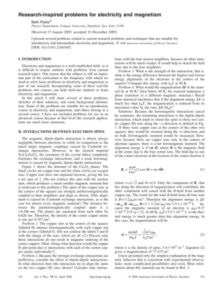
  • 1. Research-inspired problems for electricity and magnetism Beth Parksa͒ Physics Department, Colgate University, Hamilton, New York 13346 ͑Received 17 August 2005; accepted 16 December 2005͒ I present several problems related to current research problems and techniques that are suitable for introductory and intermediate electricity and magnetism. © 2006 American Association of Physics Teachers. ͓DOI: 10.1119/1.2166369͔ I. INTRODUCTION Electricity and magnetism is a well-established field, so it is difficult to inspire students with problems from current research topics. One reason that the subject is still an impor- tant part of the curriculum is the frequency with which we need to solve basic problems in electricity and magnetism as part of our research. Incorporating some of these real-life problems into courses can help motivate students to learn electricity and magnetism. In this article I will share several of these problems, sketches of their solutions, and some background informa- tion. Some of the problems are suitable for an introductory course in electricity and magnetism, and others belong in a second course. I have not included problems for use in an advanced course because at that level the research applica- tions are much more numerous. II. INTERACTIONS BETWEEN ELECTRON SPINS The magnetic dipole-dipole interaction is almost always negligible between electrons in solids in comparison to the much larger magnetic couplings caused by Coulomb ex- change interactions. However, in the layered material Sr2Cu3O4Cl2, the symmetry of the crystal lattice completely frustrates the exchange interactions, and a weak ferromag- netism is caused by magnetic dipole-dipole interactions. Figure 1 shows the structure of the Cu3O4 planes. The black circles are copper ions and the white circles are oxygen ions. Copper ions have one unpaired electron, giving the ion a net spin of 1 2. ͑Do not confuse this spin with the nuclear spin, which produces a much smaller magnetic moment that is irrelevant to this problem.͒ The spins of the copper ions at the corners of the squares are strongly antiferromagnetically coupled to their neighbors and align as shown. ͑This align- ment is caused by Coulomb exchange interactions, as is the case for almost every magnetic material.͒ The distance be- tween the antiferromagnetically coupled spins is a =0.386 nm. The planes are separated from each other by 0.626 nm. Therefore, the density of the center copper atoms is one per 0.187 nm3 . Problem 1. The copper ions at the centers of the squares ͑labeled II͒ interact ferromagnetically with each copper ion at the corners ͑labeled I͒. ͑Do not confuse the labels I and II with the charge of the ions, which are all +2.͒ Discuss why these interactions do not result in magnetic ordering of the center coppers. ͑Hint: Along what direction would the copper II spin point due to interactions with each of the corner cop- per atoms individually?͒ Problem 2. Because the stronger exchange interactions are ineffective, consider the effect of dipole-dipole interactions. In what direction does this interaction try to align the spins on the two copper ͑II͒ sites shown? Consider only interac- tions with the four nearest neighbors, because all other inter- actions will be much weaker. It would help to sketch the field lines due to the four neighbors. Problem 3. What is the strength of the interaction; that is, what is the energy difference between the highest and lowest energy alignments of the electrons at the centers of the squares? Compare this energy with kBT at 40 K. Problem 4. What would the magnetization M of the mate- rial be at 40 K? ͑Just below 40 K, the material undergoes a phase transition to a different magnetic structure.͒ Recall from statistical mechanics that if the alignment energy ⌬E is much less than kBT, the magnetization is reduced from its maximum value by the ratio ⌬E/6kBT.1 Solutions: Because the ferromagnetic interactions cancel by symmetry, the remaining interaction is the dipole-dipole interaction, which tends to orient the spins in these two cen- ter copper ͑II͒ ions along the −y-direction as defined in Fig. 1. If there were copper ions at the centers of the other two squares, they would be oriented along the +y-direction, and no bulk ferromagnetic moment would be measured. How- ever, because there are copper ions only in the centers of alternate squares, there is a net ferromagnetic moment. The alignment energy is E=m·B, where B is the magnetic field at the center due to the four corner ions. The field due to one of the corner electrons at the location of the center electron is B1 = ␮0m 4␲r3͑2 cos ␪rˆ + sin ␪␪ˆ͒, ͑1͒ where r=a/ͱ2 and ␪=␲/4. Only the component of B1 that lies along the direction of magnetization will contribute; the other component will cancel with the B-field from another copper ion. The result for the total B-field from all four ions is B=3ͱ2␮0m/␲a3 . Therefore the alignment energy is ⌬E =mup·B−mdown·B=2ϫ3ͱ2m2 ␮0/␲a3 =5.1ϫ10−24 J, be- cause the magnetic moment of an electron is ␮B=9.27 ϫ10−24 J/T ͑gϷ2͒. At 40 K, kBT=5.5ϫ10−22 J, so the ther- mal energy is much greater than this alignment energy. In this case, the magnetization will be M = nm⌬E 6kBT = ͱ2m3 n␮0 kBT␲a3 , ͑2͒ where n is the density of spins, 5.4ϫ1027 m−3 . Equation ͑2͒ gives a magnetization of 77 J/T-m3 . I have presented only the simplest explanation of the mag- netic behavior that is consistent with experimental observa- tions; more complicated possibilities also exist. More infor- mation about this material can be found in Ref. 2. 351 351Am. J. Phys. 74 ͑4͒, April 2006 http://aapt.org/ajp © 2006 American Association of Physics Teachers
  • 2. III. SQUID MAGNETOMETER Measurements of the magnetic moment as a function of applied field are essential to the characterization of supercon- ductors, ferromagnets, and antiferromagnets such as Sr2Cu3O4Cl2. A SQUID magnetometer is one of the most sensitive ways to measure the magnetic moment of a small sample. A SQUID ͑superconducting quantum interference device͒ converts a magnetic flux through its pick-up loop into a voltage that can be easily measured. When the sample is held in a magnetic field inside the magnetometer, the sample develops a dipole moment that produces a flux through the SQUID pickup loop. A charac- teristic voltage signal is produced that is proportional to the flux. ͑This phenomenon is very different from induction in a normal pickup loop in which the induced voltage is propor- tional to the rate of change of the flux.͒ The flux through the loop is a function of the distance of the sample from the loop, so as the sample is moved through the pickup loop, the voltage changes as a function of position. The magnetic mo- ment of the sample is calculated by fitting the observed variation in the voltage signal to the predicted dipole shape. Your assignment is to calculate this shape. Problem 5. The geometry is shown in Fig. 2. Assume that the pick-up loop is 2.5 cm in diameter ͑R=1.25 cm͒. The sample moves vertically in a total path of 4 cm. The voltage from the SQUID, which is proportional to the magnetic flux through the loop, is measured as a function of the position of the sample. The sample is much smaller than the loop, so you can approximate it as a perfect dipole. Calculate the shape of the signal observed. Problem 6. The magnetic moment of a 15 mm3 sample of Sr2Cu3O4Cl2 at 40 K is easily detectable. Compare the flux through the pick-up loop due to this sample to the flux of the Earth’s field. Solutions: This problem can be solved numerically or ana- lytically. In the most straightforward analytical approach, the field of the dipole is expressed in cylindrical coordinates. This expression is found most easily by starting with the vector potential of a dipole in cylindrical coordinates and taking its curl to find B. ͑It is only necessary to consider the z-component of B.͒ The result is Bz = ␮0m 4␲ 2z2 − s2 ͑s2 + z2 ͒5/2 , ͑3͒ where s is the distance from the z axis to the point at which the B-field is measured and z is the displacement of the sample from the center of the loop along the z axis. Equation ͑3͒ for Bz can be integrated over the area of the pick-up loop to find the flux as a function of the distance z between the sample and the pick-up loop: ⌽͑z͒ = ␮0m 2 R2 ͑z2 + R2 ͒3/2 , ͑4͒ where R is the radius of the pick-up loop. The flux as a function of sample position displays a characteristic peak at z=0. The problem is a bit simpler if we realize that because the divergence of B is zero, the flux is the same through the loop whether we choose the flat surface or the surface of the sphere centered on the sample. In the latter case, we can use the expression for the radial part of the B-field in spherical coordinates: Br = ␮0m 4␲r32 cos ␪. ͑5͒ Here r2 =R2 +z2 . This result for Br can easily be integrated over the area of the loop, letting ␪ range from 0 to arctan͑R/z͒, which yields the same result as before. We found that the magnetization for Sr2Cu3O4Cl2 should be 77 J/T-m3 . By using the volume given, we find that m =1.2ϫ10−6 J/T, and the maximum flux through a loop with R=0.0125 m is ␮0m/2R=7.5ϫ10−13 T-m2 . The Earth’s field is roughly 5ϫ10−5 T, so its flux through the loop is 2.5ϫ10−8 T-m2 . This difference tells us that SQUID magne- tometers must be designed very carefully to be sensitive to small changes in a large background flux. Advanced students might be asked what would be ob- served if, for some reason, the sample became magnetically polarized perpendicular to the applied magnetic field. Their first answer will ͑hopefully͒ be that the SQUID signal would be zero due to symmetry. However, you might remind them that symmetry is never perfect in real experiments; the sample will not be exactly centered in the pick-up loop. They can then numerically calculate the SQUID signal for this geometry. The resulting antisymmetric SQUID signal was the first indication that I had that something very strange was going on in the magnetism of Sr2Cu3O4Cl2; more details are in Ref. 3. IV. SUPERCONDUCTING MAGNETS Problem 7. Superconducting magnets are fairly common laboratory tools, and their strong magnetic fields sometimes have unintended effects on other experiments in the physics Fig. 1. Cu–O plane of Sr2Cu3O4Cl2. The black circles are copper ions and the white circles are oxygen ions. The two different Cu sites are labeled by Roman numerals; these labels should not be confused with the charge of the copper ion, which is +2 for both sites. Fig. 2. The SQUID produces a voltage that is proportional to the magnetic flux through the pick-up loop as the sample moves through the loop. 352 352Am. J. Phys., Vol. 74, No. 4, April 2006 Beth Parks
  • 3. building. If a superconducting magnet is roughly a solenoid 8 in. long and 3 in. in diameter with a 1 in. bore and a field of 6 T in the center, how far away from the solenoid along its axis must you be to have the magnetic field be compa- rable to that of the Earth? You may consider the current density to be uniform and in the azimuthal direction inside the solenoid. Solution: This geometry is the superposition of loops of current. Each current loop creates a field along its axis, B͑z͒ = ␮0I 2 r2 ͑r2 + z2 ͒3/2 , ͑6͒ where r is the radius of the loop and z is the distance from its center. Students should be able to set I=Jdrdz and integrate to find the field. I have not given the current density J, so students need to determine what current density would create this field in the center. They can find it by forcing the B-field to be 6 T in the center: Bcenter = 6T = ͵−L/2 L/2 ͵R1 R2 ␮0J 2 r2 ͑r2 + z2 ͒3/2 dr dz, ͑7͒ where L=8 in. is the length of the magnet, R1=0.5 in. is the inner radius, and R2=1.5 in. is the outer radius. The integral is evaluated more easily if z is integrated first. For the di- mensions given, the current density is J=1.97ϫ108 A/m2 . ͑Ask the students to compare this density to what could safely go through a copper wire.͒ Using this current density, they can find the B-field as a function of distance d from the magnet: Bd = ͵−L/2 L/2 ͵R1 R2 ␮0J 2 r2 dr dz ͑r2 + ͑d + z͒2 ͒3/2 . ͑8͒ This integral can be done, but the result is not pretty, and the equation cannot be solved for d analytically. However, at this point the student should think like a physicist. We are not looking for the exact distance; rather, we’re trying to deter- mine how far away we must go before the B-field of the magnet doesn’t matter. At this distance, it is likely that d ӷr,z. In this case, the integrand can be simplified: Bd Ϸ ͵−L/2 L/2 ͵R1 R2 ␮0J 2 r2 dr dz d3 = ␮0JL 2 R2 3 − R1 3 3d3 . ͑9͒ The result, d=2.1 m, is consistent with our initial assumption that dӷR1,R2,L and is accurate to within 0.15%. In the spirit of making reasonable approximations, a stu- dent could come up with an answer much more easily by assuming that the solenoid can be approximated by a current loop with a diameter of R=2 in. The ratio of the field at the center of the loop to the field a distance d away is ͑R2 +d2 ͒3/2 /R3 . This approach gives the result that the field will equal that of the Earth at a distance of 1.3 m, which is not as close as our previous result, but is good enough to be useful in a lab. V. MAGNETS AND OPTICAL TABLES Problem 8. In magneto-optical experiments it is necessary to place a superconducting magnet on an optical table. These tables are typically made of ferromagnetic steel. They can be made of noninductive stainless steel, but because this mate- rial is more expensive, it is avoided when possible. I recently purchased a superconducting magnet with a field of 7 T at the center of its bore. I planned to locate it on a noninductive table that was rigidly joined to an ordinary steel table. The magnet’s specifications showed that the field should be 0.01 T at a distance of 93 cm along the axis, which is roughly the distance from the magnet center to the nearest point on the steel table. According to my calcula- tions, the force between the magnet and the cryostat should be less than 500 N, or 20 lb in this location, which is much less than the weight of the magnet. However, when I con- sulted with the engineers at the cryostat company, I was told that the force between the magnet and a 2000 lb steel table would be 3.4ϫ106 lb. How did each of us arrive at our an- swers and who was right? Solution: An upper limit to the force is found by assuming that the table is an infinite plane of infinitely permeable ma- terial. This assumption makes the problem analogous to an electric dipole held above an infinite conductor: the force between them is the same as between a dipole and its mirror image. The main remaining difficulty is to find the size of the dipole. We can use the fact that the field is 0.01 T at a dis- tance of 0.93 m. This distance is certainly far enough that the dipole approximation should be valid. We find m=4.0 ϫ104 J/T. Then the force on the magnet ͑or on the table͒ is equal to the force on this dipole separated by ͑2ϫ0.93͒ m from an identical dipole. The B-field along the axis is B͑r͒ =␮0m/2␲r3 , so the force is F=ٌ͑m·B͒=m·ٌB=m‫ץ‬B/‫ץ‬r. This force is 81 N, or 18 lb. This value is a high upper bound on the actual force, because the table is not infinitely perme- able and does not occupy the entire half-plane. The approach probably taken by the magnet company was to assume that the table reaches its saturation magnetization due to the influence of the magnet. According to the CRC Handbook, steel has a saturation magnetization of around 20 000 G, which is reached at an applied field of about 100 Oe=0.01 T/␮0, roughly equal to the field at the closest point to the cryostat. Because H is negligible, the magneti- zation M is approximately B/␮0=1.6ϫ106 A/m. We can find the magnetic moment m using the mass ͑2000 lb͒ and the density ͑7800 kg/m3 ͒: m=1.9ϫ105 J/T. The force on this dipole is calculated in the same way as before, but at a distance of 0.93 m. The result of 6000 lb is still much lower than the magnet company’s estimate. I’m not sure exactly what happened in that calculation—perhaps the engineers actually used the maximum magnetic suscep- tibility of steel to overestimate the resulting magnetic moment—but I am happy to use their result in class as an example of how important it is to ensure that your answers are reasonable. If students see this second approach, they may have a difficult time deciding why it is incorrect. The error is in the assumption that the steel is fully magnetized. One way to understand it is to realize that although a small piece of steel might become fully magnetized when placed in a region with H=0.01 T/␮0, a large piece of steel will not be fully mag- netized in the same H-field. This point can be understood in terms of demagnetizing fields, but I prefer to consider an energy argument. The energy gain due to aligning with the field is M·B. The energy cost is the extra field energy cre- ated, and because the field is proportional to M, the energy is proportional to M2 . For a small M, the alignment energy is 353 353Am. J. Phys., Vol. 74, No. 4, April 2006 Beth Parks
  • 4. larger, but as M increases, the cost of creating the field in- creases. So for a sample as large as an optical table, the cost of full alignment is prohibitive. VI. CARBON NANOTUBES Carbon nanotubes are almost one-dimensional carbon structures with electrical properties that can range from semi- conducting to nearly ballistic conductance. They are objects of intense research, due both to fundamental physical interest in their one-dimensional properties and to their possible technological applications as nanoscale semiconductors and conductors. Problem 9. To measure its properties, the density of elec- trons on the nanotube is tuned by applying a voltage differ- ence between the nanotube and a ground plane, which can be approximated as an infinite conducting plane. ͑The nanotube actually rests on an insulating layer that separates it from the ground plane.͒ The density of electrons is determined by the capacitance between the nanotube and the ground plane. Cal- culate this capacitance per unit length of the nanotube. Solution: This problem can be mapped onto a fairly stan- dard problem: finding the potential due to two infinite paral- lel lines carrying opposite charge densities. It can be shown that for parallel line charges, the equipotential lines are cylinders.1 This demonstration is straightforward but not easy and should probably be given before this problem is assigned. Alternatively, the result could be provided to the students. Once that problem is solved, the difficulty of mapping the problem should not be underestimated; it was nontrivial for some of my best students. The first step is to recognize that the nanotube surface will be ͑approximately͒ an equipoten- tial, and therefore the line charges can be replaced by nano- tubes that are placed on the equipotential surfaces. ͑By using Gauss’s law, we see that the charge on the nanotube must be the same as the charge on the line.͒ The second step is to realize that the problem of two parallel nanotubes with op- posite potentials is equivalent ͑due to image charges͒ to the problem of a nanotube suspended above a conducting sur- face. Finally, it is necessary to figure out how to manipulate the results from the parallel line problem to obtain a capacitance. For lines with charge density ␭ separated by distance 2a, Griffiths1 finds that the surface with potential V0 is a circle with radius r = a cschͩ2␲⑀0V0 ␭ ͪ, ͑10͒ and its center a distance above the plane is given by y = a cothͩ2␲⑀0V0 ␭ ͪ. ͑11͒ Because a is irrelevant to the nanotube problem ͑the cylinder of constant voltage is not centered on the line charge͒, the first step is to take the ratio of these two equations to elimi- nate a. Then we can solve to find the capacitance per unit length: C/L = ␭/V0 = 2␲⑀0 cosh−1 ͑y/r͒ . ͑12͒ Typically the nanotube might have a diameter of 1.4 nm and lie on an insulating silicon oxide layer of thickness 500 nm, yielding a capacitance per unit length of 8.5 ϫ10−12 C/m. A more exact treatment of this problem would also include the dielectric constant of the insulating layer, but that correction is beyond the scope of most intermediate- level courses. Another correction is the quantum capacitance of the nanotube, that is, the additional energy an electron must have in order for it to find an unoccupied electronic state in the nanotube. This quantum capacitance turns out to be comparable in size to the geometrical capacitance calcu- lated here.4 a͒ Electronic address: meparks@mail.colgate.edu 1 David J. Griffiths, Introduction to Electrodynamics ͑Prentice Hall, Engle- wood Cliffs, NJ, 1999͒, 3rd ed., The magnetization can be found from the alignment energy using a straightforward extension of Problem 4.40 on pp. 200–201. The potential of parallel wires is considered in Problem 2.47 on p. 107. 2 F. C. Chou, Amnon Aharony, R. J. Birgeneau, O. Entin-Wohlman, M. Greven, A. B. Harris, M. A. Kastner, Y. J. Kim, D. S. Kleinberg, Y. S. Lee, and Q. Zhu, “Ferromagnetic moment and spin rotation transitions in tetragonal antiferromagnetic Sr2Cu3O4Cl2,” Phys. Rev. Lett. 78͑3͒, 535– 538 ͑1997͒. 3 Beth Parks, M. A. Kastner, Y. J. Kim, A. B. Harris, F. C. Chou, O. Entin-Wohlman, and Amnon Aharony, “Magnetization measurements of antiferromagnetic domains in Sr2Cu3O4Cl2,” Phys. Rev. B 63͑13͒, 134433-1–10 ͑2001͒. 4 Peter J. Burke, “An rf circuit model for carbon nanotubes,” IEEE Trans. Nanotechnol. 2͑1͒, 55–58 ͑2003͒. 354 354Am. J. Phys., Vol. 74, No. 4, April 2006 Beth Parks