SlideShare a Scribd company logo
1 of 25
Download to read offline
Cooperative Research Centre (CRC) for Rail Innovation
                       Showcase Event
                    Thursday 30 September 2010


Integrated Ballast–Formation-Track Design
 and Analysis including the Implications of
  Ballast Fouling and High Impact Loads
               CRC Projects R3.106 - Ballast Design

                    Buddhima Indraratna
                       Professor of Civil Engineering
         Director, Centre for Geomechanics & Railway Engineering
             Faculty of Engineering, University of Wollongong


      Other Researchers: Dr Sanjay Nimbalkar; Dr Cholachat
       Rujikiatkamjorn, Nayoma Tennakoon (PhD student)

Industry Partners: David Christie and Sandy Pfeiffer (RailCorp); Mike
         Martin and Damien Foun (QR), Tim Neville (ARTC)
Problems in Rail Track Substructure
       Clay Pumping    Differential Settlement


Void Clogging            Degradation

Coal Fouling             Poor Drainage
Ballast Fouling
            Void Contaminant Index (VCI)
                  (1+ef)       Gs.b        Mf
         VCI =             x           x        x 100
                   eb          Gs.f        Mb
           eb     = Void ratio of clean ballast
           ef     = Void ratio of fouling material
           Gs-b   = Specific gravity of ballast material
           Gs-f   = Specific gravity of fouling material
           Mb     = Dry mass of clean ballast
           Mf     = Dry mass of fouling material


            kb  k f
k
   k f  VCI      (kb  k f )
             100
Permeability Test Measurements and Predictions
                                1.E+00                   kb  k f
                                             k
                                                k f  VCI      (kb  k f )     Clay fouled ballast-Theoretical
Hydraulic Conductivity /(m/s)


                                                          100
                                1.E-01
                                                                                Coal fouled ballast-Theoretical
                                1.E-02                                          Clay fouled ballast-Experimental
                                                                                Coal fouled ballast-Experimental
                                1.E-03

                                1.E-04             Hydrulic conductivity of
                                                   coal fines

                                1.E-05
                                             Hydraulic conductivity of
                                             clayey fine sand
                                1.E-06
                                         0              20               40      60            80            100
                                                             Void Contaminant Index,VCI /(%)
Seepage model with SEEP-W
                                                   4m                        Total Head =0.5m


  Zero pore water
  pressure
                                                                                                0.3m
                                                                          45   o


  Clay fouled ballast

  Degree of Fouling     Hydraulic conductivity
  VCI (%)               k (m/s) – Lab data
                                                    Drainage Criteria – PhD work of Ms. Nayoma Tennakoon
  0%                                         0.3
  25%                                      0.02
  50%                                  0.00012           Free Drainage                          Q/Qc>50
  100%                                2.3 x 10⁻⁸         Good drainage                    5<Q/Qc<50

                                                         Acceptable drainage               1<Q/Qc<5
Equivalent Maximum Flow rate ,Qc = 0.4 litres/sec.
                                                         Poor Drainage                  0.25<Q/Qc<1
(based on an extreme precipitation event of
300mm/hour)                                              Very Poor                 0.0005<Q/Qc<0.25
Drainage capacity of the track, Q
                                                         Impervious                     Q/Qc<0.0005
Track Drainage Assessment
                                                                      Shoulder ballast maintenance
                                                                              requirement


              Shoulder
             ballast with
               0% VCI                                                                                                    Shoulder
                                                        Shoulder                                                        ballast with
                                                       ballast with                            Shoulder ballast          100% VCI
                                                        25% VCI                                 with 50% VCI
      Poor
    Drainage
                                   Poor
    (k2,k3,k4)                   Drainage
                                 (k2,k3,k4)                                   L=0.2m                         L=0.1m
    Min. VCI =
    (50,50,50)
                                Min. VCI =
                                (50,50,50)                      Poor
                                                             Drainage in
                                                              all cases                Poor Drainage
                                                                                         (k2,k3,k4)
                                                                                         Min. VCI =
                                Top ballast layer k4
                                                                                         (25,25,25)
                Middle ballast layer       k3
                                                                                                          Impervious in all
                                                                                                               cases
    Bottom Ballast layer   k2


L
L
Performance of ballast upon impact – use of shock mats
Drop Hammer - Impact Testing equipment   Weight of drop hammer = 5.81 kN (0.6 t)
                                         Maximum Height = 6 m
                                         Maximum drop velocity = 10 m/s
                                         Dynamic load cell capacity = 1200 kN


Height of the ballast sample = 300 mm
Diameter of the ballast sample= 300 mm


                                         Low confining pressures in track are
                                         similar to rubber membrane encasement
Impact Response

                          Impact force excitation during 1st Blow                                                                  Impact force excitation during 9th Blow

                    360                                                                                                      360
                                                   Fast Fourier Transform:                                                                                    Fast Fourier Transform:
                                                   Low Pass Filter (cut-off frequency 50000 Hz)                              320
                                                                                                                                                              Low Pass Filter (cut-off frequency 50000 Hz)
                    320

                    280                                                                                                      280
                                                                                                                                                                        Multiple P1 type peaks
                    240                                                                                                      240


                                                                                                         Impact force (kN)
Impact force (kN)


                    200                            Separation between the impactor and sample                                200

                    160                                                                                                      160

                    120                                                                                                      120                                                           P2 type peak

                     80                                                                                                       80

                     40                                                                                                       40

                      0                                                                                                        0
                       0.00      0.02      0.04      0.06      0.08       0.10      0.12          0.14                          0.00    0.02   0.04    0.06      0.08     0.10    0.12     0.14   0.16       0.18
                                                       time (sec)                                                                                                 time (sec)


                                           1st Blow                                                                                                   9th Blow
                              In the application of continuous blows on the same specimen, multiple
                              instantaneous P1 peaks are followed by a longer duration P2 peak.

                              It is force P2 that causes predominate ballast damage.

                              With greater breakage and subsequent compression, P2 peak
                              becomes more distinct with increasing number of blows.
Assessment of ballast breakage during impact

  1                                                                                             Subgrade   Position of shock    Ballast Breakage
                                                                          d95i
                               A                                                                  type            mat             Index (BBI)
                                         BBI        A
                                                                                    dmax
                               B                    A B
                                                                                                              Without shock mat

                                                                     ge
                                                                    ka
                   PSD = particle size distribution             ea
                                                               br
                                                                                                  Stiff            -                 0.170
Fraction Passing


                   2.36 = smallest sieve size
                                                           um


                   d95i = d95 of largest
                                                          im
                                                      ax


                          sieve size
                                                                                                  Soft             -                 0.080
                                                      m
                                                   of
                                               ry


                                                                                                               With Shock mat
                                              da


                                                                         Shift in PSD
                                          un


                                                                          caused by
                                         bo


                                                                         degradation
                                                                                                  Stiff     Above ballast            0.145
                                    ry
                                   tra
                                bi
                              Ar


                                                                                                  Stiff     Below ballast            0.129
                                                                         Initial PSD

  0
                                                                     Final PSD                    Stiff    Above & below             0.091
                       2.36
                   0                      Sieve Size (mm)                                  63                 ballast
                              Indraratna et al., 2005                                             Soft      Above ballast            0.045
                                                                                                  Soft      Below ballast            0.056
                                                                                                  Soft     Above & below             0.028
                                                                                                              ballast
Use of Geosynthetics – Process Simulation Testing
                                                                                      Number of load cycles, N
                                                       0          100000          200000             300000        400000     500000     600000
                                                   0

                                                                                           Fresh ballast (wet)
                                                                                           Recycled ballast (wet)
                                                   5
                                                           Rapid increase                  Recycled ballast with geotextile (wet)


                             Settlement, S (mm)
                                                           in settlement
                                                                                           Recycled ballast with geogrid (wet)
                                                  10                                       Recycled ballast with geocomposite (wet)


                                                  15


                                                  20


                                                                                Stabilisation
                                                  25


                                              Settlement of ballast with and without geosynthetics
                                                                                            Grain size (mm)
                                                       0           10            20             30            40        50          60     70
                                                   4
                                                                                                                     Highest breakage
                                                                        Effect of geosynthetics

Prismoidal Triaxial Rig to                         2


Simulate a Track Section      D Wk (%)
                                                   0

(Specimen: 800600600 mm)
                                                  -2                        Fresh ballast (wet)
                                                                            Recycled ballast (wet)
                                                                            Recycled ballast with geotextile (wet)
                                                  -4
                                                                            Recycled ballast with geogrid (wet)
                                                                            Recycled ballast with geocomposite (wet)

                                                  -6


                                                           Effect of Geosynthetics on Ballast Degradation
From Theory to Practice: Use of Geosynthetics in Bulli Track


                 Details of instrumented track


        Section of ballasted track bed with geocomposite layer
Preparation of Fully Instrumented Trial Track in Bulli


                          Geocomposite layer
                          (geogrid+geotextile)
                          before ballast
                                                 Ballast placement
                          placement
                                                 over the geocomposite     8 October 2006


                                                                           Geotextile


 Recycled Ballast                      Fresh Ballast
                                                                         Bonded Geogrid
from Chullora Quarry, Sydney       Bombo Quarry, Wollongong
Field Instrumentation in Bulli


      Settlement pegs            Displacement
      installed at ballast-      transducers installed at
      capping interface          sleeper-ballast interface
Deformation of Ballast
(Indraratna et al, ASCE, JGGE, 2010)
                                                                             Number of load cycles, N                                                                                                                                                                                          Number of load cycles, N
                                                             5          5          5           5          5          5          5          5       5                                                                                                                                  5          5          5          5          5          5       5
                                                  0   1x10       2x10       3x10        4x10       5x10       6x10       7x10       8x10       9x10                                                                                                                        0   1x10       2x10       3x10       4x10       5x10       6x10       7x10
                                              0                                                                                                   0.00                                                                                                                -0                                                                            -0.00


                                                                                                                                                                                                            Average lateral displacement of ballast, (S h)avg (mm)
                                                                                         Fresh Ballast (uniform graded)                                                                                                                                                                                Fresh Ballast (uniform graded)


                                                                                                                                                         Average vertical strain of ballast, ( 1)avg (%)
 Mean settlement of ballast, (S v)avg (mm)


                                                                                                                                                                                                                                                                                                                                                            Average lateral strain of ballast, 3)avg (%)
                                              3
                                                                                         Recycled Ballast (well graded)                           1.00
                                                                                                                                                                                                                                                                      -2                               Recycled Ballast (well graded)               -0.08
                                                                                         Fresh Ballast with Geocomposite                                                                                                                                                                               Fresh Ballast with Geocomposite
                                                                                         Recycled Ballast with Geocomposite                                                                                                                                           -4                               Recycled Ballast with Geocomposite           -0.16
                                              6                                                                                                   2.00

                                                                                                                                                                                                                                                                      -6                                                                            -0.24
                                              9                                                                                                   3.00
                                                                                                                                                                                                                                                                      -8                                                                            -0.32

                                             12                                                                                                   4.00
                                                                                                                                                                                                                                                                     -10                                                                            -0.40

                                             15                                                                                                   5.00
                                                                                                                                                                                                                                                                     -12                                                                            -0.48


                                             18                                                                                                   6.00                                                                                                               -14                                                                            -0.56
                                                  0    2          4          6            8         10         12         14         16         18                                                                                                                         0    2          4           6         8          10         12         14
                                                                                       time, t (months)                                                                                                                                                                                              time, t (months)


                                  Mean settlement (Sv)avg and                                                                                                                                               Average lateral displacement (Sh)avg
                                  average vertical strain (1)avg                                                                                                                                           and average lateral strain (3)avg

                        The recycled ballast performs well, if a well-graded PSD is adopted (Cu = 1.8) and
                        stabilised with geogrids.

                        A well-graded recycled ballast (Cu>2) can provide a higher placement density, hence
                        a reduced settlement compared to a Uniform ballast (Cu<1.5) .
Use of Shock Mats & Geogrids in Practice: Singleton (NSW) – R3.117


      Soft Subgrade: Embankment fill      Stiff Subgrade: Hard rock cutting


                                            Types of Geosynthetic
                                            Biaxial Geogrid - TerraGrid TG3030 (Polyfabrics)
                                            Biaxial Geogrid - Tensar Geogrid SSLA30
                                            (Geofabrics Australasia)
                                            Biaxial Geogrid - EnkaGrid MAX 30 (Maccaferri)
                                            Geocomposite - Combigrid 40/40 Geogrid +
                                            Geotextile (Global Synthetics)
                                            Shock mat (10 mm thick)
Instrumented Track for Performance Monitoring - Singleton


                                              Settlement pegs
                Geogrid layer placed          placement in the track
                above the capping


                Pressure cells below
                the sleeper                  Mudies Creek Bridge
                                             pressure cells installation
PLAXIS - Finite Element Analysis
                                                                                                                                                 Vertical stress under rail, v (kPa)
                                                                                                                                 0       50           100        150          200           250          300
                                                                                                                             0


                                                                                     Depth below base of sleeper, z (mm)
                                                                                                                           150
                                                                                                                                                                                         Ballast layer


                                                                                                                           300
                                                                                                                                                                                    Sub-ballast layer

                                                                                                                                                                            Elasto-plastic Model
                                                                                                                                                                            Field Data
                                                                                                                           450


                                                              Ultimate redistribution of vertical stress

                                                                                                                                              Settlement under rail, Sv (mm)
                                                                                                                                 0   5           10         15         20           25        30         35
                                                                                                                            0


                                                                  Depth below base of sleeper, z (mm)
Because of symmetry, adequate to consider half of the
                                                                                                                    150
    track                                                                                                                                                                                Ballast layer


Axle load of 25 tonnes and dynamic impact factor of
                                                                                                                    300
    1.43 (@ speed of 80 km/h on standard gauge)                                                                                                                                     Sub-ballast layer

                                                                                                                                                                            Elasto-plastic Model

 FEM predictions are underestimated because                                                                         450
                                                                                                                                                                            Field Data


 breakage is not captured well
                                                                    Ultimate settlement with depth
If breakage is captured with associated plastic flow, then the settlement prediction will be more
accurate.
New Design Procedures – UoW method
        (Systematic Method of Analysis of Rail Track – SMART)
    Criterion 1: Critical Shear Strength (ballast or subgrade)


                                                                UOW


Conventional Li and Selig approach     UoW Ballast Parameters
Criterion 2: Critical track deformation
  (Plastic vertical strains for (a) ballast = 8%; (b) subgrade = 2%)


                                                                       UOW


Conventional Li and Selig approach        UoW ballast parameters
Single Subgrade Layer    Formulation of            Multiple Subgrade Layers


                        SMART Approach
                        (to be completed in 2012
                          under R3.117 project)
Conclusions

•   The track drainage is assessed using a new parameter, ‘Void
    Contaminant Index’ - VCI that takes into account the specific gravity of
    different fouling materials.
•   Recycled ballast stabilised with Geosynthetics can perform as well as
    fresh ballast
•   Shock mats improve the performance of ballast by reducing the
    breakage caused by impact loads. Effectiveness depends on the
    subgrade stiffness.
•   Field trials conducted in Bulli and Singleton (NSW) demonstrate the
    advantages of Field Performance Monitoring, apart from calibrating
    FEM-based design technique.
•   UOW research outcomes are continually captured in a MATLAB based
    design approach: SMART (Systematic Method of Analysis of Rail
    Tracks).
Acknowledgement
 Australian Research Council (2 Discovery Projects and 3 Linkage
  Projects since 1993).
 Cooperative Research Centre for Railway Engineering and Technologies
  (Rail CRC) (Project 6/139) from 2000-2007
 Cooperative Research Centre (CRC for Rail Innovation)
 ARC Centre of Excellence for Geotechnics (funded in 2010).
 Industry Partners:
   RailCorp, QR, and ARTC.
 David Christie (RaiCorp, Sydney)
 Tim Neville (ARTC, Newcastle)
 Michael Martin, Damien Foun (QR, Brisbane)
 Sandy Pfeiffer (RaiCorp, Sydney)
 UOW Researchers: Dr Joanne Lackenby, Dr Wadud Salim, Dr. Sanjay
  Nimbalkar, Ms. Nayoma Tennakoon, Dr Cholachat Rujikiatkamjorn
 UOW Technical Staff: Alan Grant, Cameron Neilson, Ian Bridge
Test materials – Specifications
Material   Particle   dmax   dmin    d50    Cu                100
           Shape      (mm)   (mm)    (mm)
                                                              90
Fresh      Highly     63.0   19.0    35.0   1.6
Ballast    angular                                            80               Sand

Subgrade      -       4.75   0.075   0.48   2.3               70
(sand)                                                                                                                   Fresh Ballast
                                                              60


                                                  % passing
                                                              50


                                                              40

                                                                                                               Australian Standard
                                                              30                                               AS 2758.7 (1996)

                                                              20                                UoW new gradation
                                                                                                Indraratna and Salim (2005)
                                                              10

                                                               0
                                                               0.010   0.100           1.000                         10.000              100.000
                                                                                      Particle Size (mm)


                                                                                      Fine sand as subgrade


                                            Shock mat (10 mm thick)
                                            made of recycled rubber
                                            (polyurethane)
                                            Damping Ratio = 0.08
Multiple Impact Loading with Shock Mats
                                                                     Number of blows, N                                                                                             Number of blows, N
                                           0     1     2       3     4     5       6      7      8     9     10                                           0     1     2       3     4     5       6      7      8     9       10
                                      52                                                                                                             52
                                                                                                                                                                                                No Shock mat
                                      48                                                                                                             48
                                                                                                                                                                                                Shock mat at top


                                                                                                                    Maximum Impact Force, P 2 (kN)
                                                                                                                                                                                                Shock mat at bottom
      Maximum Impact Force, P2 (kN)


                                      44                                                                                                             44
                                                                                                                                                                                                Shock mat at top and bottom
                                      40                                                                                                             40

                                      36                                                                                                             36

                                      32                                                                                                             32

                                      28                                                                                                             28
                                                                                  No Shock mat
                                      24                                          Shock mat at top                                                   24
                                                                                  Shock mat at bottom
                                      20                                          Shock mat at top and bottom                                        20

                                           0.0   0.6   1.2    1.7   2.3    2.9    3.5     4.1    4.6   5.2   5.8                                          0.0   0.6   1.2    1.7   2.3    2.9    3.5     4.1    4.6   5.2     5.8
                                                             Cumulative Impact Energy, E (kNm)                                                                              Cumulative Impact Energy, E (kNm)


   Very Stiff Subgrade – steel plate                                                                               Natural Softer Subgrade - sand
The P2 force shows a significant increase with the extent of cumulative impact energy.

For stiff subgrade, shock mat is more effective in reducing P2 when located at the
bottom of ballast than at the top.

A soft subgrade itself serves as an energy absorber, hence the benefits of the shock mat are
generally marginal. However, if the shock mat is placed at the top of ballast to attenuate the
impulse waves, then P2 is reduced (less breakage).

More Related Content

More from CRC for Rail Innovation

2011 CRC Showcase - Safety & Security Theme - Safer level crossings
2011 CRC Showcase - Safety & Security Theme - Safer level crossings2011 CRC Showcase - Safety & Security Theme - Safer level crossings
2011 CRC Showcase - Safety & Security Theme - Safer level crossingsCRC for Rail Innovation
 
2010 CRC Showcase - Climate Change & Environment - Accelerated Depreciation R...
2010 CRC Showcase - Climate Change & Environment - Accelerated Depreciation R...2010 CRC Showcase - Climate Change & Environment - Accelerated Depreciation R...
2010 CRC Showcase - Climate Change & Environment - Accelerated Depreciation R...CRC for Rail Innovation
 
2010 CRC Showcase - Climate Change & Environment - Noise R1.105
2010 CRC Showcase - Climate Change & Environment - Noise R1.1052010 CRC Showcase - Climate Change & Environment - Noise R1.105
2010 CRC Showcase - Climate Change & Environment - Noise R1.105CRC for Rail Innovation
 
2010 CRC Showcase - Safety & Security - Next Generation Fatigue Models R2.110
2010 CRC Showcase  - Safety & Security - Next Generation Fatigue Models R2.1102010 CRC Showcase  - Safety & Security - Next Generation Fatigue Models R2.110
2010 CRC Showcase - Safety & Security - Next Generation Fatigue Models R2.110CRC for Rail Innovation
 
2010 CRC Showcase - Safety & Security - Safety Culture Management R2.101
2010 CRC Showcase - Safety & Security - Safety Culture Management R2.1012010 CRC Showcase - Safety & Security - Safety Culture Management R2.101
2010 CRC Showcase - Safety & Security - Safety Culture Management R2.101CRC for Rail Innovation
 
2010 CRC Showcase - Workforce Development - R1.111 R1.112 & R1.113
2010 CRC Showcase - Workforce Development - R1.111 R1.112 & R1.1132010 CRC Showcase - Workforce Development - R1.111 R1.112 & R1.113
2010 CRC Showcase - Workforce Development - R1.111 R1.112 & R1.113CRC for Rail Innovation
 
2010 CRC Showcase - Workforce Development - Full Skills Recognition P4.111
2010 CRC Showcase - Workforce Development - Full Skills Recognition P4.1112010 CRC Showcase - Workforce Development - Full Skills Recognition P4.111
2010 CRC Showcase - Workforce Development - Full Skills Recognition P4.111CRC for Rail Innovation
 
2010 CRC Showcase- Workforce Development - Evaluating Track Safety Awareness...
2010 CRC Showcase-  Workforce Development - Evaluating Track Safety Awareness...2010 CRC Showcase-  Workforce Development - Evaluating Track Safety Awareness...
2010 CRC Showcase- Workforce Development - Evaluating Track Safety Awareness...CRC for Rail Innovation
 
2010 CRC Showcase Urban Rail - Urban Rail Demand Management R1.107
2010 CRC Showcase   Urban Rail - Urban Rail Demand Management R1.1072010 CRC Showcase   Urban Rail - Urban Rail Demand Management R1.107
2010 CRC Showcase Urban Rail - Urban Rail Demand Management R1.107CRC for Rail Innovation
 
2010 CRC Showcase - Workforce Development - E-learning for Rail P4.110
2010 CRC Showcase - Workforce Development - E-learning for Rail P4.1102010 CRC Showcase - Workforce Development - E-learning for Rail P4.110
2010 CRC Showcase - Workforce Development - E-learning for Rail P4.110CRC for Rail Innovation
 
Presentation to CRC Participants Workshop
Presentation to CRC Participants WorkshopPresentation to CRC Participants Workshop
Presentation to CRC Participants WorkshopCRC for Rail Innovation
 
CEO Presentation to CRC Participants Workshop
CEO Presentation to CRC Participants WorkshopCEO Presentation to CRC Participants Workshop
CEO Presentation to CRC Participants WorkshopCRC for Rail Innovation
 

More from CRC for Rail Innovation (19)

2011 CRC Showcase - Safety & Security Theme - Safer level crossings
2011 CRC Showcase - Safety & Security Theme - Safer level crossings2011 CRC Showcase - Safety & Security Theme - Safer level crossings
2011 CRC Showcase - Safety & Security Theme - Safer level crossings
 
2010 CRC Showcase - Climate Change & Environment - Accelerated Depreciation R...
2010 CRC Showcase - Climate Change & Environment - Accelerated Depreciation R...2010 CRC Showcase - Climate Change & Environment - Accelerated Depreciation R...
2010 CRC Showcase - Climate Change & Environment - Accelerated Depreciation R...
 
2010 CRC Showcase - Climate Change & Environment - Noise R1.105
2010 CRC Showcase - Climate Change & Environment - Noise R1.1052010 CRC Showcase - Climate Change & Environment - Noise R1.105
2010 CRC Showcase - Climate Change & Environment - Noise R1.105
 
2010 CRC Showcase - Safety & Security - Next Generation Fatigue Models R2.110
2010 CRC Showcase  - Safety & Security - Next Generation Fatigue Models R2.1102010 CRC Showcase  - Safety & Security - Next Generation Fatigue Models R2.110
2010 CRC Showcase - Safety & Security - Next Generation Fatigue Models R2.110
 
2010 CRC Showcase - Safety & Security - Safety Culture Management R2.101
2010 CRC Showcase - Safety & Security - Safety Culture Management R2.1012010 CRC Showcase - Safety & Security - Safety Culture Management R2.101
2010 CRC Showcase - Safety & Security - Safety Culture Management R2.101
 
2010 CRC Showcase - Workforce Development - R1.111 R1.112 & R1.113
2010 CRC Showcase - Workforce Development - R1.111 R1.112 & R1.1132010 CRC Showcase - Workforce Development - R1.111 R1.112 & R1.113
2010 CRC Showcase - Workforce Development - R1.111 R1.112 & R1.113
 
2010 CRC Showcase - Workforce Development - Full Skills Recognition P4.111
2010 CRC Showcase - Workforce Development - Full Skills Recognition P4.1112010 CRC Showcase - Workforce Development - Full Skills Recognition P4.111
2010 CRC Showcase - Workforce Development - Full Skills Recognition P4.111
 
2010 CRC Showcase- Workforce Development - Evaluating Track Safety Awareness...
2010 CRC Showcase-  Workforce Development - Evaluating Track Safety Awareness...2010 CRC Showcase-  Workforce Development - Evaluating Track Safety Awareness...
2010 CRC Showcase- Workforce Development - Evaluating Track Safety Awareness...
 
2010 CRC Showcase Urban Rail - Urban Rail Demand Management R1.107
2010 CRC Showcase   Urban Rail - Urban Rail Demand Management R1.1072010 CRC Showcase   Urban Rail - Urban Rail Demand Management R1.107
2010 CRC Showcase Urban Rail - Urban Rail Demand Management R1.107
 
2010 CRC Showcase - Workforce Development - E-learning for Rail P4.110
2010 CRC Showcase - Workforce Development - E-learning for Rail P4.1102010 CRC Showcase - Workforce Development - E-learning for Rail P4.110
2010 CRC Showcase - Workforce Development - E-learning for Rail P4.110
 
State of Rail in Australia
State of Rail in AustraliaState of Rail in Australia
State of Rail in Australia
 
Rail research collaboration in Europe
Rail research collaboration in EuropeRail research collaboration in Europe
Rail research collaboration in Europe
 
Presentation to CRC Participants Workshop
Presentation to CRC Participants WorkshopPresentation to CRC Participants Workshop
Presentation to CRC Participants Workshop
 
CEO Presentation to CRC Participants Workshop
CEO Presentation to CRC Participants WorkshopCEO Presentation to CRC Participants Workshop
CEO Presentation to CRC Participants Workshop
 
Underpinning Rail Workforce Development
Underpinning Rail Workforce DevelopmentUnderpinning Rail Workforce Development
Underpinning Rail Workforce Development
 
The Time For High Speed Rail
The Time For High Speed RailThe Time For High Speed Rail
The Time For High Speed Rail
 
Operations And Safety
Operations And SafetyOperations And Safety
Operations And Safety
 
Engineering for Performance Improving
Engineering for Performance ImprovingEngineering for Performance Improving
Engineering for Performance Improving
 
The CRC for Rail Innovation - About Us
The CRC for Rail Innovation - About UsThe CRC for Rail Innovation - About Us
The CRC for Rail Innovation - About Us
 

2010 CRC Showcase - Performance - Ballast Design R3.106

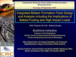
  • 1. Cooperative Research Centre (CRC) for Rail Innovation Showcase Event Thursday 30 September 2010 Integrated Ballast–Formation-Track Design and Analysis including the Implications of Ballast Fouling and High Impact Loads CRC Projects R3.106 - Ballast Design Buddhima Indraratna Professor of Civil Engineering Director, Centre for Geomechanics & Railway Engineering Faculty of Engineering, University of Wollongong Other Researchers: Dr Sanjay Nimbalkar; Dr Cholachat Rujikiatkamjorn, Nayoma Tennakoon (PhD student) Industry Partners: David Christie and Sandy Pfeiffer (RailCorp); Mike Martin and Damien Foun (QR), Tim Neville (ARTC)
  • 2. Problems in Rail Track Substructure Clay Pumping Differential Settlement Void Clogging Degradation Coal Fouling Poor Drainage
  • 3. Ballast Fouling Void Contaminant Index (VCI) (1+ef) Gs.b Mf VCI = x x x 100 eb Gs.f Mb eb = Void ratio of clean ballast ef = Void ratio of fouling material Gs-b = Specific gravity of ballast material Gs-f = Specific gravity of fouling material Mb = Dry mass of clean ballast Mf = Dry mass of fouling material kb  k f k k f  VCI  (kb  k f ) 100
  • 4. Permeability Test Measurements and Predictions 1.E+00 kb  k f k k f  VCI  (kb  k f ) Clay fouled ballast-Theoretical Hydraulic Conductivity /(m/s) 100 1.E-01 Coal fouled ballast-Theoretical 1.E-02 Clay fouled ballast-Experimental Coal fouled ballast-Experimental 1.E-03 1.E-04 Hydrulic conductivity of coal fines 1.E-05 Hydraulic conductivity of clayey fine sand 1.E-06 0 20 40 60 80 100 Void Contaminant Index,VCI /(%)
  • 5. Seepage model with SEEP-W 4m Total Head =0.5m Zero pore water pressure 0.3m 45 o Clay fouled ballast Degree of Fouling Hydraulic conductivity VCI (%) k (m/s) – Lab data Drainage Criteria – PhD work of Ms. Nayoma Tennakoon 0% 0.3 25% 0.02 50% 0.00012 Free Drainage Q/Qc>50 100% 2.3 x 10⁻⁸ Good drainage 5<Q/Qc<50 Acceptable drainage 1<Q/Qc<5 Equivalent Maximum Flow rate ,Qc = 0.4 litres/sec. Poor Drainage 0.25<Q/Qc<1 (based on an extreme precipitation event of 300mm/hour) Very Poor 0.0005<Q/Qc<0.25 Drainage capacity of the track, Q Impervious Q/Qc<0.0005
  • 6. Track Drainage Assessment Shoulder ballast maintenance requirement Shoulder ballast with 0% VCI Shoulder Shoulder ballast with ballast with Shoulder ballast 100% VCI 25% VCI with 50% VCI Poor Drainage Poor (k2,k3,k4) Drainage (k2,k3,k4) L=0.2m L=0.1m Min. VCI = (50,50,50) Min. VCI = (50,50,50) Poor Drainage in all cases Poor Drainage (k2,k3,k4) Min. VCI = Top ballast layer k4 (25,25,25) Middle ballast layer k3 Impervious in all cases Bottom Ballast layer k2 L L
  • 7. Performance of ballast upon impact – use of shock mats Drop Hammer - Impact Testing equipment Weight of drop hammer = 5.81 kN (0.6 t) Maximum Height = 6 m Maximum drop velocity = 10 m/s Dynamic load cell capacity = 1200 kN Height of the ballast sample = 300 mm Diameter of the ballast sample= 300 mm Low confining pressures in track are similar to rubber membrane encasement
  • 8. Impact Response Impact force excitation during 1st Blow Impact force excitation during 9th Blow 360 360 Fast Fourier Transform: Fast Fourier Transform: Low Pass Filter (cut-off frequency 50000 Hz) 320 Low Pass Filter (cut-off frequency 50000 Hz) 320 280 280 Multiple P1 type peaks 240 240 Impact force (kN) Impact force (kN) 200 Separation between the impactor and sample 200 160 160 120 120 P2 type peak 80 80 40 40 0 0 0.00 0.02 0.04 0.06 0.08 0.10 0.12 0.14 0.00 0.02 0.04 0.06 0.08 0.10 0.12 0.14 0.16 0.18 time (sec) time (sec) 1st Blow 9th Blow In the application of continuous blows on the same specimen, multiple instantaneous P1 peaks are followed by a longer duration P2 peak. It is force P2 that causes predominate ballast damage. With greater breakage and subsequent compression, P2 peak becomes more distinct with increasing number of blows.
  • 9. Assessment of ballast breakage during impact 1 Subgrade Position of shock Ballast Breakage d95i A type mat Index (BBI) BBI  A dmax B A B Without shock mat ge ka PSD = particle size distribution ea br Stiff - 0.170 Fraction Passing 2.36 = smallest sieve size um d95i = d95 of largest im ax sieve size Soft - 0.080 m of ry With Shock mat da Shift in PSD un caused by bo degradation Stiff Above ballast 0.145 ry tra bi Ar Stiff Below ballast 0.129 Initial PSD 0 Final PSD Stiff Above & below 0.091 2.36 0 Sieve Size (mm) 63 ballast Indraratna et al., 2005 Soft Above ballast 0.045 Soft Below ballast 0.056 Soft Above & below 0.028 ballast
  • 10. Use of Geosynthetics – Process Simulation Testing Number of load cycles, N 0 100000 200000 300000 400000 500000 600000 0 Fresh ballast (wet) Recycled ballast (wet) 5 Rapid increase Recycled ballast with geotextile (wet) Settlement, S (mm) in settlement Recycled ballast with geogrid (wet) 10 Recycled ballast with geocomposite (wet) 15 20 Stabilisation 25 Settlement of ballast with and without geosynthetics Grain size (mm) 0 10 20 30 40 50 60 70 4 Highest breakage Effect of geosynthetics Prismoidal Triaxial Rig to 2 Simulate a Track Section D Wk (%) 0 (Specimen: 800600600 mm) -2 Fresh ballast (wet) Recycled ballast (wet) Recycled ballast with geotextile (wet) -4 Recycled ballast with geogrid (wet) Recycled ballast with geocomposite (wet) -6 Effect of Geosynthetics on Ballast Degradation
  • 11. From Theory to Practice: Use of Geosynthetics in Bulli Track Details of instrumented track Section of ballasted track bed with geocomposite layer
  • 12. Preparation of Fully Instrumented Trial Track in Bulli Geocomposite layer (geogrid+geotextile) before ballast Ballast placement placement over the geocomposite 8 October 2006 Geotextile Recycled Ballast Fresh Ballast Bonded Geogrid from Chullora Quarry, Sydney Bombo Quarry, Wollongong
  • 13. Field Instrumentation in Bulli Settlement pegs Displacement installed at ballast- transducers installed at capping interface sleeper-ballast interface
  • 14. Deformation of Ballast (Indraratna et al, ASCE, JGGE, 2010) Number of load cycles, N Number of load cycles, N 5 5 5 5 5 5 5 5 5 5 5 5 5 5 5 5 0 1x10 2x10 3x10 4x10 5x10 6x10 7x10 8x10 9x10 0 1x10 2x10 3x10 4x10 5x10 6x10 7x10 0 0.00 -0 -0.00 Average lateral displacement of ballast, (S h)avg (mm) Fresh Ballast (uniform graded) Fresh Ballast (uniform graded) Average vertical strain of ballast, ( 1)avg (%) Mean settlement of ballast, (S v)avg (mm) Average lateral strain of ballast, 3)avg (%) 3 Recycled Ballast (well graded) 1.00 -2 Recycled Ballast (well graded) -0.08 Fresh Ballast with Geocomposite Fresh Ballast with Geocomposite Recycled Ballast with Geocomposite -4 Recycled Ballast with Geocomposite -0.16 6 2.00 -6 -0.24 9 3.00 -8 -0.32 12 4.00 -10 -0.40 15 5.00 -12 -0.48 18 6.00 -14 -0.56 0 2 4 6 8 10 12 14 16 18 0 2 4 6 8 10 12 14 time, t (months) time, t (months) Mean settlement (Sv)avg and Average lateral displacement (Sh)avg average vertical strain (1)avg and average lateral strain (3)avg The recycled ballast performs well, if a well-graded PSD is adopted (Cu = 1.8) and stabilised with geogrids. A well-graded recycled ballast (Cu>2) can provide a higher placement density, hence a reduced settlement compared to a Uniform ballast (Cu<1.5) .
  • 15. Use of Shock Mats & Geogrids in Practice: Singleton (NSW) – R3.117 Soft Subgrade: Embankment fill Stiff Subgrade: Hard rock cutting Types of Geosynthetic Biaxial Geogrid - TerraGrid TG3030 (Polyfabrics) Biaxial Geogrid - Tensar Geogrid SSLA30 (Geofabrics Australasia) Biaxial Geogrid - EnkaGrid MAX 30 (Maccaferri) Geocomposite - Combigrid 40/40 Geogrid + Geotextile (Global Synthetics) Shock mat (10 mm thick)
  • 16. Instrumented Track for Performance Monitoring - Singleton Settlement pegs Geogrid layer placed placement in the track above the capping Pressure cells below the sleeper Mudies Creek Bridge pressure cells installation
  • 17. PLAXIS - Finite Element Analysis Vertical stress under rail, v (kPa) 0 50 100 150 200 250 300 0 Depth below base of sleeper, z (mm) 150 Ballast layer 300 Sub-ballast layer Elasto-plastic Model Field Data 450 Ultimate redistribution of vertical stress Settlement under rail, Sv (mm) 0 5 10 15 20 25 30 35 0 Depth below base of sleeper, z (mm) Because of symmetry, adequate to consider half of the 150 track Ballast layer Axle load of 25 tonnes and dynamic impact factor of 300 1.43 (@ speed of 80 km/h on standard gauge) Sub-ballast layer Elasto-plastic Model FEM predictions are underestimated because 450 Field Data breakage is not captured well Ultimate settlement with depth If breakage is captured with associated plastic flow, then the settlement prediction will be more accurate.
  • 18. New Design Procedures – UoW method (Systematic Method of Analysis of Rail Track – SMART) Criterion 1: Critical Shear Strength (ballast or subgrade) UOW Conventional Li and Selig approach UoW Ballast Parameters
  • 19. Criterion 2: Critical track deformation (Plastic vertical strains for (a) ballast = 8%; (b) subgrade = 2%) UOW Conventional Li and Selig approach UoW ballast parameters
  • 20. Single Subgrade Layer Formulation of Multiple Subgrade Layers SMART Approach (to be completed in 2012 under R3.117 project)
  • 21. Conclusions • The track drainage is assessed using a new parameter, ‘Void Contaminant Index’ - VCI that takes into account the specific gravity of different fouling materials. • Recycled ballast stabilised with Geosynthetics can perform as well as fresh ballast • Shock mats improve the performance of ballast by reducing the breakage caused by impact loads. Effectiveness depends on the subgrade stiffness. • Field trials conducted in Bulli and Singleton (NSW) demonstrate the advantages of Field Performance Monitoring, apart from calibrating FEM-based design technique. • UOW research outcomes are continually captured in a MATLAB based design approach: SMART (Systematic Method of Analysis of Rail Tracks).
  • 22. Acknowledgement  Australian Research Council (2 Discovery Projects and 3 Linkage Projects since 1993).  Cooperative Research Centre for Railway Engineering and Technologies (Rail CRC) (Project 6/139) from 2000-2007  Cooperative Research Centre (CRC for Rail Innovation)  ARC Centre of Excellence for Geotechnics (funded in 2010).  Industry Partners: RailCorp, QR, and ARTC.  David Christie (RaiCorp, Sydney)  Tim Neville (ARTC, Newcastle)  Michael Martin, Damien Foun (QR, Brisbane)  Sandy Pfeiffer (RaiCorp, Sydney)  UOW Researchers: Dr Joanne Lackenby, Dr Wadud Salim, Dr. Sanjay Nimbalkar, Ms. Nayoma Tennakoon, Dr Cholachat Rujikiatkamjorn  UOW Technical Staff: Alan Grant, Cameron Neilson, Ian Bridge
  • 23.
  • 24. Test materials – Specifications Material Particle dmax dmin d50 Cu 100 Shape (mm) (mm) (mm) 90 Fresh Highly 63.0 19.0 35.0 1.6 Ballast angular 80 Sand Subgrade - 4.75 0.075 0.48 2.3 70 (sand) Fresh Ballast 60 % passing 50 40 Australian Standard 30 AS 2758.7 (1996) 20 UoW new gradation Indraratna and Salim (2005) 10 0 0.010 0.100 1.000 10.000 100.000 Particle Size (mm) Fine sand as subgrade Shock mat (10 mm thick) made of recycled rubber (polyurethane) Damping Ratio = 0.08
  • 25. Multiple Impact Loading with Shock Mats Number of blows, N Number of blows, N 0 1 2 3 4 5 6 7 8 9 10 0 1 2 3 4 5 6 7 8 9 10 52 52 No Shock mat 48 48 Shock mat at top Maximum Impact Force, P 2 (kN) Shock mat at bottom Maximum Impact Force, P2 (kN) 44 44 Shock mat at top and bottom 40 40 36 36 32 32 28 28 No Shock mat 24 Shock mat at top 24 Shock mat at bottom 20 Shock mat at top and bottom 20 0.0 0.6 1.2 1.7 2.3 2.9 3.5 4.1 4.6 5.2 5.8 0.0 0.6 1.2 1.7 2.3 2.9 3.5 4.1 4.6 5.2 5.8 Cumulative Impact Energy, E (kNm) Cumulative Impact Energy, E (kNm) Very Stiff Subgrade – steel plate Natural Softer Subgrade - sand The P2 force shows a significant increase with the extent of cumulative impact energy. For stiff subgrade, shock mat is more effective in reducing P2 when located at the bottom of ballast than at the top. A soft subgrade itself serves as an energy absorber, hence the benefits of the shock mat are generally marginal. However, if the shock mat is placed at the top of ballast to attenuate the impulse waves, then P2 is reduced (less breakage).