SlideShare uma empresa Scribd logo
1 de 82
Baixar para ler offline
1
CONTENTS
ABSTRACT 8
List of figures 6-7
Title Page No
CHAPTER.1. INTRODUCTION 9-10
CHAPTER.2. WORKING OF DRONE 11-18
2.1. Arrangement of motors. 12-14
2.1.1. Attach propellers. 13
2.1.2. recognizing CW and CCW propellers. 14
2.2. Driving 15-18
2.2.1. Hovering and take off quad copter. 16
2.2.2. Drone tilting. 17
2.2.3. Yaw 17
2.2.4. Pitch 18
2.2.5. Roll 18
CHAPTER.3. BLOCK DIAGRAM 19-20
3.1. Power source. 19
3.2. ground control station. 19
3.3. Arduino mega 2560. 20
2
3.4. Global position system(GPS). 20
3.5. Electronic speed controller(ESC). 20
3.6. Brush less DC motor(BLDC). 20
CHAPTER.4 COMPONENTES DESCRIPTION 21-36
4.1. Frame. 21-36
4.1.1. Arm of drone. 22
4.2. Motors. 23
4.3. Propellers. 23-24
4.4. Electronic speed controller(ESC). 24-25
4.5. Lithium polymer battery(LiPo). 25-32
4.5.1. LiPo battery rating. 24-28
4.5.2. charging of LiPo. 28-32
4.6. On board pilot controller. 33
4.7. Radio transmitter and receiver. 34
4.8. Global position system(GPS). 35
4.9. Power module. 35
4.10. Landing gears. 36
CHAPTER.5. CIRCUIT CONNECTIONS
CHAPTER.6. SET UP FOR APM 2.8(ON BORD PILOT CONTROLLER) 38-79
6.1. Features of APM 2.8 40-41
3
6.2. Mission planner software. 41-42
6.2.1. Installing mission planner. 41
6.2.2. Download most recent mission planner. 42
6.2.3. Run the installation utility. 42
6.3. Inner view of APM 2.8 43
6.4. APM 2.8 wiring diagram. 44
6.5. Powering the flight controller. 45-46
6.5.1. connecting the power module(PM) to flight controller.45-46
6.6. Loading firmware into APM 2.8 47-50
6.6.1. Connect controller to computer. 47
6.6.2. Connect to mission planner. 47-48
6.6.3. Install firmware. 48-49
6.6.4. Setup connections. 49-50
6.6.4.1. Troubleshooting. 50
6.7. MANDATORY HARDWARE COFIGURATION. 51-53
6.7.1. Frame type configuration in mission planner. 51-52
6.7.2. Compass calibration. 52-54
6.7.2.1. on board compass live calibration. 53
6.8 Radio calibration. 54-60
6.8.1. Transmitter configuration. 54
6.8.2. Channel mapping. 56
4
6.8.3. preconditions. 56
6.8.4. Center trims. 56
6.8.5. Connect auto pilot and turn on Receiver. 56-57
6.8.6. calibration steps. 58
6.9. Accelerometer calibration in mission planner. 61-63
6.9.1. Calibration steps. 61
6.10. RC Transmitter flight mode configuration. 64
6.10.1 flight mode configuration. 64
6.11. Electronic speed controller(ESC) calibration. 65-69
6.11.1. About electronic speed controller(ESC) calibration. 65
6.11.2. Waring for electronic speed controller(ESC). 66
6.11.3. All at one calibration. 67-69
6.12. First flight with quad copter. 70
6.12.1. Flight mode. 70
6.13. Pre-Arm safety check. 71
6.13.1. Recognizing which Pre-Arm check. 71
6.13.2. Failure message when drone ready to fly. 71-75
6.14. Disable the Pre-Arm safety check. 75
6.15. Arming the motors. 76-77
6.16. Disarming the motors. 77
6.17. Tips for new pilots. 77-78
5
6.17.1. First flight. 77-78
6.17.2. Tips for your first flight. 78
6.18. Waring about low battery. 78-79
CHAPTER.7. CONCLUSION 80-81
7.1. Future of drone 80-81
CHAPTER.8. BIBILOGRAPHY 82
6
LIST OF FIGURES
1. Body of drone (Fig.1.1)
2. Rotation of motors (Fig.2. (a))
3. Frame type and motors setup (Fig.2.1. (a), Fig.2.1. (b))
4. Attach propellers (Fig.2.1.1. (a))
5. Recognizing of propels (Fig.2.1.1. (b))
6. Placing of motors on H and X shape frame (Fig.2.2. (a))
7. Hovering and take-off (Fig.2.2.1. (a))
8. Tilting (Fig.2.2.2. (a))
9. Yaw (Fig.2.2.3. (a))
10. Pitch (Fig.2.4. (a))
11. Roll (Fig.2.2.5. (a))
12. Block diagram (Fig.3. (a))
13. Distribution board (Fig.4.1. (a))
14. Arm of drone (Fig.4.1.1. (a))
15. BLDC motor (Fig.4.2. (a))
16. Propellers (Fig.4.3. (a))
17. Electronic speed controller (ECS) (Fig.4.4. (a))
18. LiPo battery (Fig.4.5. (a))
19. Rating of LiPo battery (Fig.4.5.1. (a))
20. On board pilot controller (Fig.4.6. (a), (Fig.4.6. (b))
21. Transmitter and receiver (Fig.4.7. (a))
22. Global position system(GPS) (Fig.4.8. (a))
23. Power module(PM) (Fig.4.9. (a))
24. Landing gears (Fig.4.10. (a))
25. Circuit connections of drone (Fig.5. (a))
26. Setup for APM 2.8 (Fig.6. (a))
27. APM 2.8 protection packing (Fig.6. (b))
28. APM Firmware (Fig.6.1. (a))
29. APM mission planner software (Fig.6.2. (a))
30. Run and installation utility (Fig.2.2. (a))
31. Inner view of APM 2.8 (Fig.6.3. (a))
7
32. APM wring diagram (Fig.6.4. (a))
33. Powering to flight controller (Fig.6.5. (a))
34. Power module connection (Fig.6.5.1. (a), (Fig.6.5.1. (b))
35. Connect flight controller to computer (Fig.6.6.1. (a))
36. Connect to mission planner (Fig.6.6.2. (a))
37. Mission planner firmware install screen (Fig.6.6.3. (a))
38. APM USB connection (Fig.6.6.4. (a))
39. Connection using 3DR radio (Fig.6.6.4. (b), (c), (d))
40. Select frame type (Fig.6.7.1. (a))
41. Compass calibration (Fig.6.7.2. (a))
42. Compass live calibration (Fig.6.7.2. (b))
43. Transmitter mode 1 (Fig.6.8.1. (a))
44. Transmitter mode 2 (Fig.6.8.1. (b))
45. Radio Calibration screen (Fig.6.8.5. (a))
46. Radio calibration is done (Fig.6.8.6. (a))
47. Result of radio channel ranging (Fig.6.8.6. (b))
48. Final result of radio channels (Fig.6.8.6. (c))
49. Calibrate acceleration (Fig.6.9.1. (a))
50. Accelerometer Calibration Positions (Fig.6.9.1. (b))
51. Accele calibration is done (Fig.6.9.1. (c))
52. Calibration successful (Fig.6.9.1. (c))
53. Flight mode screen (Fig.6.10.1. (a))
54. Waring for ESC calibration (Fig.6.11.2. (a))
55. All ESC at once calibration (Fig.6.11.3. (a), (b), (c), (d))
56. Accelerometer and gyro heck (Fig.6.13.1. (a))
57. Disabling the Pre-arm safety check (Fig.6.14. (a))
58. Our drone flying photo (Fig.7. (a))
8
ABSTRACT
A quadcopter can achieve vertical flight in a stable manner and used
to monitor or collect data in a specific region such as Loading a mass.
The goal of this project is to build, modify, and improve an existing
quadcopter kit to obtain stable flight, gather and store GPS data, and
perform auto commands, such as auto-landing. Technological advances
have reduced the cost and increase the performance of the low power
microcontrollers that allowed the general public to develop their own
quadcopter. The project used an Aero quad quadcopter kit that included
a frame, motors, electronic speed controllers, Arduino Mega development
board, and sensor boards and used with the provided Aero quad
software. Batteries, a transmitter, a receiver, a GPS module was
interfaced with the kit. The aero quad software was modified to properly
interface the components with the quadcopter kit. Individual components
were tested and verified to work properly. Calibration and tuning of the
PID controller was done to obtain proper stabilization on each axis using
custom PID test benches. Currently, the quadcopter can properly
stabilize itself, determine its GPS location, and store log data. Most of the
goals in this project have been achieved, resulting in a stable and
pilotable quadcopter.
The goal of this project is to design and build an autonomous
quadcopter from scratch. This means going through the process of
researching previous models, performing calculations, purchasing
individual parts, testing those parts, designing the final product,
designing an APM2.8 based controllers, and finally fitting everything
together. All this is to be done with the minimum amount of outside help
we can manage (i.e. not using pre-determined code, not buying a boxed
set of materials). After deciding how big we wanted our quadcopter to be
and purchasing the appropriate parts there were four primary design
steps on the way to the final product.
9
CHAPTER.1
INTRODUCTION
Drone is also called as UAV (Unmanned aerial vehicle). Which is
having on board flight controller on vehicle. Quad-copter(Drone) is a
device with an intense mixture of Electronics, Mechanical and mainly on
principle of Aviation.
A quad copter, also called a quadrotor helicopter or quad rotor is a
multirotor helicopter that is lifted and propelled by four rotors. Quad
copters are classified as rotorcraft, as opposed to fixed-wing aircraft,
because their lift is generated by a set of rotors (vertically oriented
propellers).
Quad copters differ from conventional helicopters use rotors which
are able to vary the pitch of their blades dynamically as they move
around the rotor hub. In the early days of flight, quad copters (then
referred to either as 'quad rotors' or 'helicopters') were seen as possible
solutions to some of the persistent problems in vertical flight; torque-
induced control issues (as well as efficiency issues originating from the
tail rotor, which generates no useful lift) can be eliminated by counter-
rotation and the relatively short blades are much easier to construct.
These vehicles were among the first successful heavier-than-air vertical
take-off and landing (VTOL)vehicles.
A Drone or Quadcopter is a Vehicles have large potential for
performing tasks that are dangerous or very costly for humans.
Examples are the inspection of high structures, humanitarian purposes
or search-and-rescue missions. One specific type of Drone is becoming
increasingly more popular lately the quadcopter. When visiting large
events or parties, professional quadcopters can be seen that are used to
capture video for promotional or surveillance purposes.
Recreational use is increasing as well for less than 50 Euros a small
remote controlled quadcopter can be bought to fly around in your living
room or garden. In these situations, the quadcopter is usually in free
flight. There is no physical contact between the surroundings and the
quad copter and no cooperation between the quadcopters If would have
the capabilities to collaborate the number of possibilities grows even
further. For example, a group of Drone would be able to efficiently and
10
autonomously search a missing person in a large area by sharing data
between. Or, the combined load capacity of a group of quad copters can
be used to deliver medicine in remote areas. This bachelor thesis focuses
on the use of a commercially available quadcopter platform, the. Drone,
to perform a task that requires physical collaboration and interaction:
moving a mass. In this way a clear interaction between the quadcopters
and their surroundings is present. As preliminary step towards the view
of collaborating aerial robots the choice was made to perform this task in
an indoor scenario where position feedback is present. Starting off with
position control, additional controller logic can be implemented to
counteract the forces imposed by a mass connected to the quadcopter.
The choice is made for the Drone, a generalized approach is chosen
where possible to encourage reuse of this research’s outcome and
deliverables.
Fig.1.1
A helicopter is a flying vehicle which uses rapidly spinning rotors to
push air downwards, thus creating a thrust force keeping the helicopter
aloft. Conventional helicopters have two rotors. These can be arranged as
two coplanar rotors both providing upwards thrust, but spinning in
opposite directions (in order to balance the torques exerted upon the
body of the helicopter). see above Fig1.1
11
CHAPTER.2
WORKING OF DRONE(QURDCOPTER)
Working principle of quadcopter is mainly consisting of increase and
decrease the speed of the motors, to drive the quadcopter(drone). A
quadrotor hovers or adjusts its altitude by applying equal thrust to all
four rotors. Rotation of motors are shown in Fig.2.a
Quadcopters generally use two pairs of identical fixed pitched
propellers, two clockwise (CW) and two counter-clockwise (CCW). These
uses independent variation of the speed of each rotor to achieve control.
By changing the speed of each rotor it is possible to specifically generate
a desired total thrust; to locate for the center of thrust both laterally and
longitudinally and to create a desired total torque, or turning force.
Fig.2. (a)
12
2.1 ARRANGEMENT OF MOTORS
The sections below show motor order for each frame type (the
numbers indicates the connected autopilot output pin) and the propeller
direction (clockwise (CW) motors are shown in green and take pusher
propellers, counterclockwise motors (CCW) are shown in blue and take
puller propellers. Propeller
Use the diagram for your frame type, and wire the motors as shown in
bellow Fig.2.1. (a) and Fig.2.1. (b).
Legend for motor-order diagrams
Quad copter
Fig.2.1. (a)
Place motors on quad copter frame any model. But, will place all
motors are equal distance from a center point, it is like Triangle, square,
hex, etc.
There is alternating arrangement of motors on drone. Use Fig 2.1. (b)
is acceptable model for to build drone frame.
13
Fig.2.1. (b)
2.1.1 Attach propellers
Find your frame in the motor order diagrams above. Clockwise motors
are shown in green, marked CW, and take pusher propellers.
Counterclockwise motors are shown in blue, marked CCW, and take
puller propellers. Use the Fig.2.1. (a) for your frame type, and attach
propellers to your vehicle as shown. For copters, attach propellers with
the writing facing towards the sky. For more information on recognizing
the different types of propellers, see in bellow Fig 2.1.1. (a)
Fig.2.1.1. (a)
14
Recognizing clockwise and counterclockwise propellers
The Fig.2.1.1. (b) bellow show two types of propellers: clockwise
(called pushers) and counterclockwise (called pullers). Pusher propellers
are often marked with a P. However not all propellers are marked and
both types are often available in either rotational direction. Therefore, it
is most reliable to recognize the correct propeller type by its shape as
shown below. Reminder that the propellers below have the edge with the
shallow consistent curve at the leading edge in direction of rotation and
the more radical scalloped (and usually thinner edge) as the trailing edge.
You can use these features to recognize propellers of the correct direction
of rotation. Recognize of propellers are shown in Fig.2.1.1. (b).
Fig.2.1.1. (b)
To arrange propellers on motors like Fig.2.2. (b), then controlling of
drone (quad copter) will easy. If all motors are rotating single direction
the vehicle will not controllable. The force which is generated by one
direction rotating motors will be compensating by the other direction
rotating motor’s force, the at this time drone is stable, easy to control
and it not dangers to environmental.
15
2.2. DRIVING OF DRONE(QUADCOPTER)
Fig.2.2. (a)
This is quadcopter placed upon a H or X shaped frame.
In this above Fig.2.2. (a) we using quad copter will be placing of
motors like H shape as and X shape. Both two shapes are used for drone
motors. Four motors A, B, C, and d are placed equal distance from the
center of its body shape.
If motors of drone con not place according into Fig.2.2. (a) the forces
generating by motors are not compensating each. This result drone (quad
copter) control is very complicated as well as it is cause to injure to living
being which are in the field.
16
2.2.1 Hovering and take - off quadcopter(drone)
For hovering a balance of forces is needed. If we want the quad-copter
to hover, SUM(Fi) must be equal m•g. To move the quad-copter
climb/decline the speed of every motor is increased/decreased.
➢ SUM(Fi) > m•g <=> climb
➢ SUM(Fi) = m•g <=> hover
➢ SUM(Fi) < m•g <=> decline
See Below Fig.2.2.1.1
Fig.2.2.1. (a)
17
2.2.2. Quadcopter(drone)tilting
Now let take a look on what is happening when we tilt the quad-
copter. For simplification, only two of the four rotors are shown. We see
that the force is divided in two different parts. FL1 and FL2 are the part
of the force used to lift the quad-copter. FT1and FT2 represents the part
used for the translation. It is obvious that the lift part becomes smaller
with increasing φ. Tilting of drone is shown in Fig.2.2.2. (a).
Fig.2.2.2. (a)
2.2.3 Yaw
Yaw is the deviation/Rotating the head of the quadcopter either to
right or left, Yaw can be controlled through the throttle stick, also called
rudder, making it to rotate either to the left or right. (Or) Yaw is simply
defined as the rotation of a UAV with respect to the center axis. If you
were looking down on a drone from above, yaw refers to the movement of
the drone clockwise or counter clockwise. yaw is shown in Fig.2.2.3. (a).
Fig.2.2.3. (a)
18
2.2.4 Pitch
Pitch is the movement of quadcopter either forward and backward.
Forward Pitch is achieved by pushing the aileron stick forward, which
makes the quadcopter tilt and move forward, away from you.
Backward pitch is achieved by moving the aileron stick
backwards(towards you), making the quadcopter, come closer to us.
Pitch of drone is shown in Fig.2.2.4. (a).
Fig.2.4. (a)
2.2.5 ROLL
Roll is making the quadcopter fly sideward, either to left or right. Roll
is controlled with the aileron stick, making it move left of right, if you
move the aileron stick to the left, the quadcopter will fly left, if you move
the aileron stick to right, the quadcopter will fly right. Roll of drone is
shown in the Fig..2.5. (a)
Fig.2.2.5. (a)
19
CHAPTER.3
BLOCK DIAGRAM
Fig.3. (a)
Above Fig.3. a is shown the block diagram of drone
3.1 POWER SOURCE
In this drone block diagram, we are LiPo battery as power source. It is
give power to directly to ESC (electronic speed controller).
3.2 GOUND CONTROL STATION
Ground control station is a control strategy for control of drone as
well as to monitor the drone through computer and mobile phone etc.
Normally for this ground control station we are using 3DR radio
telemetry. This also use for to set up flight planning, to set PID values
when drone in air, to change radio channel when drone in air etc.
20
3.3 ARDUINO MEGA 2560
This is an on-board pilot which is monitoring all operation which are
going in drone system.
This contain bellow meters
1. Accelerometer: This is use to find tilting of vehicle. It will
give the vehicle’s tilting angle to Arduino Mega 2560.Taking
this information the controller will generate the signals and
give those to ESC (electronic speed controller).
2. Gyro meter: Gyro meter is for to fly the vehicle with respect
to our input. If any other physical forces are acting on
vehicle the Gyro meter will minimized those physical forces.
It is used for navigation of drone.
3. Magneto meter: Is used for orientation, navigation of
drone.
4. Barometer: It can provide the atmospheric pressure to
controller.
Arduino Mega 2560 will collect data from all meters, I will check it is
comfortable to fly or not. If the environment is good all meters are
working proper way, the Arduino Mega 2560 will response to radio signal
(arming).
3.4 GPS (global position system)
GSP (global position system) it is a hardware which is used to find
location of drone. In advance this GPS will use for navigation of a drone.
GPS was connected to a 5pin GSP port in APM 2.8.
3.5 ESC (electronic speed controller)
This a circuit which is used for to control of brush less DC motor’s
speed. ESC are connecting in between distribution board and BLDC
motors, and ESC signal wire is connected to APM2.8.
3.6 BLDC (brush less DC motors)
Brush less DC motors (BLDC) coupled with propellers are to give
thrust to drone which is using to drive the drone in the air. BLDC motors
are connected output of ESC.
21
CHAPTER.4
COMPONENTES DESCRIPTION
4.1 FRAME
Just as important as good electronics, multi-rotors depend on sturdy,
lightweight hulls for mounting components. There are countless frame
designs of varying shapes, dimensions, and materials. Stiffer frames
confer better flight characteristics, since less warping and bending can
occur. If a frame is too brittle, though, your inevitable crashes will result
in more frequent repair sessions. Frames need to be both strong and
stiff, whilst being light enough to hop around in the sky with ease.
One of the most common materials for multi-rotor frames is carbon
fiber. A great many of its physical properties are perfectly suited to the
hobby. The only catch is that carbon fiber is known to block radio
signals, which is obviously not ideal for a hobby that depends on
multiple transmissions. It can be used though, and is often. Just be
aware that blocked signals are a possibility.
Frames can also be built at home using aluminum or balsa sheet. But
results will vary from manufactured frames, both aesthetically and in
terms of flight attributes.
Common is the integration of power distribution circuits into the
frame plates. Battery connections are soldered directly to pads built into
the material, and power can be tapped at other solder points without the
need for extensive, messy wiring. Although by no means essential, a
clean setup is satisfying and less likely to fail, making power-distributing
frames a worthy investment.
Frame with distribution board is shown in Fig.4.1. (a).
22
Fig.4.1. (a)
4.1.1 Arms
Arms can be built at home using aluminum or hard plastic tubing.
However, for many hobbyists, it's preferable to go with pre-built arms.
These components are relatively cheap and easy to replace. Therefore,
they're generally considered a pre-determined breaking point. In the
event of a crash, the arms should be the first to give, preventing damage
to motors or expensive electronics on the frame. You actually want them
to be a bit brittle, particularly on a heavier, crash-prone quad.
Quad copter arm shown in Fig.4.1.1. (a)
Fig.4.1.1. (a)
23
4.2 MOTORS
1000Kv Brushless Quadcopter Motors is a Brushless DC electric
motor (BLDC motors) also known as electronically commutated motors
(ECMs, EC motors) are synchronous motors that are powered by a DC
electric source via an integrated inverter switching power supply, which
produces an AC electric signal to drive the motor. In this context, AC,
alternating current, does not imply a sinusoidal waveform, but rather a
bi-directional current with no restriction on waveform.
The motors chosen should meet the
following specifications:
▪ Lightweight.
▪ High speed and torque.
▪ PWM speed controlled.
We chose A2212/13T (1000KV) brushless motor. Fig.4.2. (a)
4.3 PROPELLER
It is a device which converts the rotational motion into thrust. the
drone propellers for the quads are small in size and usually made up of
plastic material. there are altogether four propellers; two move in the
clockwise direction and two moves in the anti-clockwise
direction. Propellers are always categorized according to the length and
the pitch. Pitch is the distance travelled by drone in one single prop
rotation. The propellers with lower pitches produce more torque,
therefore, the motor can operate on less current. In case if we are using a
high pitch prop, then more air will get displaced and this will result in a
commotion. Due to this, our drone would shake while hovering. Thus, a
lower pitch propeller we used. Propellers are shown in Fig.4.3. (a).
24
▪ Dimension: 10X4.7 inch.
▪ 4 propellers.
▪ Directly attached to motor.
▪ 2 each rotating CW and CCW (“pusher "and a “normal").
▪ Propeller use for to drive the drone(quadcopter).
Fig.4.3. (a)
4.4 ELECTRONIC SPEED CONTROLLER (ESC)
An electronic speed control or ESC is an electronic circuit with the
purpose to vary an electric motor's speed, its direction and possibly also
to act as a dynamic brake. ESCs are often used on electrically
powered radio controlled models, with the variety most often used
for brushless motors essentially providing an electronically
generated three-phase electric power low voltage source of energy for the
motor. ESC is shown in Fig.4.4. (a).
▪ The motor speed is set by the ESC in response to a pulse width
modulated control signal.
25
▪ The motor speed is then proportional to the root-mean-square
(RMS) value of the armature voltage.
Fig.4.4. (a).
4.5 LiPo BATTERY
Properties
▪ Lightweight.
▪ High discharging current and capacity.
▪ low internal resistance.
▪ long working time.
Fig.4.5. (a)
Lithium Polymer (LiPo) are achieve these characteristics
4.5.1 LiPo battery ratings
26
LiPo battery basics, time to get into the main topics at hand. First are
ratings, specifically voltage and capacity. These are the two main
numbers you will need when going battery shopping. There are a couple
others you will also need to know about, but they are arbitrary and not
concrete like the first two.
bellow Fig.4.5.1. (a) shown the rating of LiPo batteries
Fig.4.5.1. (a)
1. Voltage (shown in red in above photo)
Unlike conventional NiCad or NiMH battery cells that have a nominal
voltage of 1.2 volts per cell, LiPo battery cells have a nominal voltage of
3.7 volts per cell. The benefit here is fewer cells can be used to make up
a battery pack and in some cases on smaller micro sized RC aircraft like
most toy helicopters or hobby grade micros like the Blade mCX2, or Nano
QX, a single 3.7 volt LiPo cell is all that is needed to power the model.
Other than the smallest of electric RC models, RC LiPo battery packs
will have at least two or more cells hooked up in series to provide higher
voltages. For larger RC models that number can be as high as 6 cells and
even more for larger birds or HV (high voltage) applications. Here is a list
of LiPo RC battery pack voltages with cell counts. If you are wondering
what the 1-12S in parenthesis means; it's the way battery manufacturers
indicate how my cells hooked in series(S) the battery pack contains.
• 3.7 volt battery = 1 cell x 3.7 volts (1S)
• 7.4 volt battery = 2 cells x 3.7 volts (2S)
• 11.1 volt battery = 3 cells x 3.7 volts (3S)
• 14.8 volt battery = 4 cells x 3.7 volts (4S)
27
• 18.5 volt battery = 5 cells x 3.7 volts (5S)
• 22.2 volt battery = 6 cells x 3.7 volts (6S)
• 29.6 volt battery = 8 cells x 3.7 volts (8S)
• 37.0 volt battery = 10 cells x 3.7 volts (10S)
• 44.4 volt battery = 12 cells x 3.7 volts (12S)
2. CAPACITY (shown in green)
Capacity indicates how much power/energy the battery pack can
hold and is indicated in milliamp hours (mAh). This is just a fancy
way of saying how much load or drain (measured in milliamps) can
be put on the battery for 1 hour at which time the battery will be
fully discharged.
For example, an RC LiPo battery that is rated at 1000 mAh would
be completely discharged in one hour with a 1000 milliamp load
placed on it. If this same battery had a 500-milliamp load placed
on it, it would take 2 hours to drain down. If the load was
increased to around 15,000 milliamps (15 amps); a very common
current drain in a 3S powered 450 sized RC helicopter while
hovering - the time to drain the battery would be only about 4
minutes.
As you can see, for a RC model with that kind of current draw, it
would be very advantageous to use a larger capacity battery pack
such as a 2000 mAh pack. This larger pack used with a 15-amp
draw would double the time to about 8 minutes till the pack was
discharged.
The main thing to get out of this is if you want more flight time;
increase the capacity of your battery pack. Unlike voltage, capacity
can be changed around to give you more or less flight time.
Naturally because of size & weight restrictions, you have to stay
within a certain battery capacity range seeing that the more
capacity a battery pack has, the larger and heavier it will be.
• Think of increasing the RC LiPo battery capacity similar to putting
a larger fuel tank in the RC vehicle.
4. DISCHARGE RATE (shown in yellow)
This one is probably the single most over rated &
misunderstood of all battery ratings.
rate is simply how fast a battery can be discharged safely.
Remember that ion exchange thing further up the page? Well the
faster the ions can flow from anode to cathode in a battery will
28
indicate the discharge rate. In the RC LiPo battery world it is called
the “C” rating.
What does it mean?
Well Capacity begins with “C” so that should give you a pretty
good idea. A battery with a discharge rating of 10C would mean
you could theoretically & safely discharge it at a rate 10 times
more than the capacity of the pack, a 15C pack = 15 times more, a
20C pack = 20 times more, and so on.
Using our 1000 mAh battery as an example; if it has a 20C
discharge rating, that would mean you could pull a maximum
sustained load up to 20,000 milliamps or 20 amps off that battery
(20 x 1000 milliamps = 20,000 milliamps or 20 amps).
From a purely theoretical time stand point, this equals 333
mAh of draw per minute so the 1000 mAh pack would be
completely exhausted in about 3 minutes if it's exposed to the
maximum rated 20C discharge rate the entire time.
Calculation as follows: 20,000 mA divided by 60 minutes = 333
mAh which is then divided into the 1000 mAh capacity of the pack
giving us 3.00 minutes).
Most RC LiPo Battery packs will show the continuous C rating
and usually a maximum burst C rating as well. A burst rating
indicates the battery discharge rate for short bursts (a few seconds
maximum) of extended power. An example might be something like
"Discharge rate = 25C Continuous/50C Bursts".
The higher the C rating, usually the more expensive and even
slightly heavier the battery gets. This is where you can save some
money, and maybe even a little weight. Getting an extremely high
discharge rated pack when there is no way you could possibly pull
the full amount of power is not required but it won't hurt either.
The most important thing is you can't go with too low a discharge
C rating or you will damage your battery and possibly your ESC
(electronic speed control).
4.5.2 Charging LiPo batteries
Charging RC LiPo Batteries is a topic in itself. LiPo, Li Ion, and Li Fe
batteries obviously have some very different characteristics from
conventional RC rechargeable battery types. Therefore, charging them
correctly with a charger specifically designed for lithium chemistry
batteries is critical to both the lifespan of the battery pack, and your
safety.
A 3.7 volt RC LiPo battery cell is 100% charged when it reaches 4.2
volts. Charging it past that will shorten life substantially. In fact, the cell
29
phone industry did a study looking at the effect of LiPo fully charged
voltages in relation to cycle life. These tests were done under ideal
laboratory conditions and of course the 80% depth of discharge rule was
obeyed! Here are the results:
• Charge to 4.1V gave over 2000 cycles.
• Charge to 4.2V gave about 500 cycles.
• Charge to 4.3V gave under 100 cycles.
• Charge to 4.4V gave less than 5 cycles.
Folks in the RC world have reported similar results and one ongoing
test seems to indicate if you set your maximum charge voltage to 4.15
volts per cell (if your computerized charge gives you that option), you
should be able to get about 800 cycles (again if all the other LiPo usage
rules are religiously obeyed). More and more people are considering this
4.15 termination voltage the "sweet spot" for both performance and cycle
life for RC usage. Most RC chargers don't give you that ability, but if
yours does, you may want to consider it. One caveat to this I should
mention are the new generation of "high voltage" LiPo cells. There are a
few manufacturers that are producing LiPo cells that can handle as high
as 4.35 volts and maintain a 500 cycle life.
No matter what your maximum charge termination voltage is, keeping
each cell in the RC LiPo battery pack at that same voltage is another
important rule to understand once I start talking about Balancing RC
LiPo batteries, so keep that in the back of your head for right now. It is
critical that you use a charger specified for LiPo batteries and select the
correct voltage or cell count when charging your RC LiPo batteries if you
are using a computerized charger. If you have a 2 cell (2S) pack you must
select 7.4 volts or 2 cells on your charger. If you selected 11.1V (a 3S
pack) by mistake and tried to charge your 2S pack, the pack will be
destroyed and most likely catch fire. Luckily, all the better computerized
chargers out there these days will warn you if you selected the wrong cell
count.
All LiPo battery chargers will use the constant current / constant
voltage charging method (cc/cv). All this means is that a constant
current is applied to the battery during the first part of the charge cycle.
As the battery voltage closes in on the 100% charge voltage, the charger
will automatically start reducing the charge current and then apply a
constant voltage for the remaining phase of the charge cycle. The charger
will stop charging when the 100% charge voltage of the battery pack
equalizes with charger’s constant voltage setting (4.2 volts per cell) at this
time, the charge cycle is completed. Going past that to 4.3 volts will
shorten battery life substantially as we have already seen.
30
LiPo Battery Charging Current
Selecting the correct charge current is also critical when charging RC
LiPo battery packs. The golden rule here remains to be "never charge a
LiPo, LiIon, or LiFe pack greater than 1 times its capacity (1C)."
For example, a 2000 mAh pack, would be charged at a maximum
charge current of 2000 mA or 2.0 Amps. Going higher will shorten the
life of the pack. Moreover, if you choose a charge rate significantly higher
than the 1C value, the battery will heat up and could puff up.
Higher than 1C charge rates...
Most LiPo experts say you can safely charge at a 2C or even 3C rate
on quality packs that have a discharge rating of at least 20C or more and
have low internal resistances safely, but it will reduce LiPo life. Even
though there are more and more LiPo packs showing up stating 2C, 3C,
4C and even 5C charge rates; this is just indicating it's still safe to
charge at those rates and not risk thermal runaway within the battery;
but it really has nothing to do with actual battery life. The simple fact is
constantly charging any LiPo over 1C will have an impact on its life
expectancy.
I will charge at higher than 1C rates on occasion when I'm in a rush
to get out to the field or want to get into the air again quickly; but I
always try to charge at 1C or lower rates most of the time. It all boils
down to speed vs. life and your budget. If you don't mind taking some life
out of your packs in favour of getting back in the air or out on the track
ASAP, then charging at higher C rates might be a viable compromise for
your particular needs. I would also strongly recommend never charging
over 1C if the ambient air temperature (and the pack) is over 30C (about
90F).
The seven main things that shorten LiPo battery life are:
1. HEAT
2. LEAVING A LIPO FULLY CHARGED FOR SEVERAL DAYS
3. OVER DISCHARGING (voltage & current)
4. OVER CHARGING (voltage & current)
5. INADEQUATE BALANCING
6. IMPROPER STORAGE VOLTAGE (more on that shortly)
7. PHYSICAL DAMAGE (dropping, over tightening straps, prying cells
apart, using too much/too strong Velcro etc.)
31
Here are my 5 simple LiPo Charging Safety Tips that I follow
• I usually charge all my larger multi celled LiPo’s directly on the
concrete floor in the shop well away from any combustibles.
• I always wait at least 15 minutes after using a LiPo to let it cool
down before charging it. This prolongs the life of the LiPo and
prevents possible overheating and damage.
• I never ever leave the house (preferably the room) when charging
LiPo’s.
• I store all my LiPo's in a metal tool chest in various compartments
so if one goes up in smoke it hopefully won't take them all. Ammo
boxes are also an excellent choice. I don't trust LiPo sacks or bags
at all! They are a complete waste of money for all but small packs
IMO. You can pick up surplus ammo boxes for less money and
they offer superior protection.
• Lastly – I purchased an inexpensive smoke detector that I have
mounted above my charging area & storage chest so in the unlikely
event a pack bursts during a charge cycle or while in storage, the
smoke detector will sound and I will be alerted. I also have a small
fire extinguisher mounted on the wall in my workshop for any fire
that may occur, not just a LiPo fire. This may seem excessive,
chances are it is... but after watching the video below, I feel these
are worthwhile precautions.
4.5.3 RC LiPo Battery Storage
A LiPo cell that drops below 3 volts under load (about 3.6V open
circuit voltage) is almost always & irreversibly damaged. It will have
reduced capacity or total inability to accept a charge due to cell
oxidation. If your batteries are stored for any period of time after you use
them at close to that magic 3.6 volt per cell number, you risk irreversible
damage.
As batteries sit, they will naturally self-discharge. LiPo’s are actually
very good in this respect and self-discharge much slower than most other
rechargeable battery types, but they still do lose capacity as they sit
(about 1% per month). If you leave them for a number of weeks or
months in a near fully discharged state, chances are they may be
irreversibly damaged as the cells oxidize.
You must store them charged, but not fully charged either – that will
also degrade/oxidize the cell matrix.
Fully charged LiPo batteries are not happy and must be used soon
after they are fully charged. They are very much like F1 cars sitting
on the grid!
32
Basically, the speed at which a LiPo pack ages (during storage) is
based on both storage temperature and state of charge. You are likely
okay to store a fully charged RC LiPo battery at room temperature for up
to 2 days without doing too much damage. Never ever store a LiPo in a
hot car fully charged for an extended time, that will certainly cause
damage (puffed and may even vent) as I explained earlier, but it's worth
repeating. For optimum battery life, store your RC LiPo batteries in a cool
room if possible (slows down the chemical reaction) at about a 40-60%
charged state. That equates to around 3.85 volts per cell (open terminal
resting voltage). The actual storage range is likely a little broader than
this (I have heard some say numbers as high as 30-80% is fine, but since
computerized chargers set the storage charge at 50% (3.85 volts per cell)
that's recommend and what i follow myself.
You can actually extend the fully charged storage time from a couple
days to weeks by storing your batteries in the fridge (not freezer) close to
0 degrees Celsius (32F); again, that helps slow down the chemical
reaction that oxidizes the cathode in the cells. I have started doing this
with my smaller packs seeing that I will often find myself wanting to go
flying little micros with little lead time and it is very convenient having
packs already fully charged. If you do store your fully charged LiPo's in
the fridge, pack them in a zip-lock freezer bag and squeeze out all the air
before sealing the bag. This will prevent condensation forming on the
battery packs when you take them out of the fridge as they warm up.
You should allow the LiPo pack to warm up after removing from the
fridge before using it of course. Small micro LiPo's warm quickly, big
packs don't. This is why I only use the "fully charged cold storage"
method with micro packs.
33
4.6 ON BOARD PILOT CONTROLLER
ArduPilot (APM 2.8)
Fig.4.6. (a)
• Collects sensor data.
• Receives control commands.
• Calculates orientation.
• Control motor speed.
We use ArduPilot (APM 2.8) in our project
Fig.4.6. (b)
34
4.7 TRANSMITTER AND RECIVER
• This wireless receiver provides a simple, straight-forward receiver
for all of low-cost wireless project.
• Features:
▪ 2.4 GHz
▪ 1000 m Range transmitter shown in Fig.4.7. (a)
Fig.4.7. (a)
For the drone (quad copter) minimum 6 channel transmitter and
receiver require. Using this transmitter will allocate the driving of drone
follow.
Channel number Channel function
1 Aileron
2 Elevator
3 Thrust
4 Rudder
5 Flight
6 PID tuning for clean flight
35
4.8 Global Position System(GPS)
A drone with GPS and autopilot system including camera gives you
plenty of aerial options. As well as flying its programmed route. GPS will
also use to tracing and navigation of the drone.
For this application, we want to use an efficient signal providing GPS
module.
Now a days uBlox 7M is most suitable for tracing and navigation of
drone. UBlox 7M is shown in Fig.4.8. (a).
Fig.4.8. (a)
4.9. POWER MODULE(PM)
In APM 2.8 we want provide a constant voltage to board for operating
properly as well as to monitoring of board voltage and current.so we are
using power module(PM). bellow Fig.4.9. a is shown the power module
picture.
Fig.4.9. (a)
36
4.10 LANDING GEARS
Usually the landing gears use for landing the drone without any
damage. Another think when drone in take-off landing gears are used for
to compensating ground interface on sensors which are located in on
board pilot controller (APM 2.8).
We are using these landing gears in shown in Fig.4.10. (a).
Fig.4.10. (a)
37
CHAPTER.5
CIRCUIT CONNECTIONS
Fig.5. (a)
Connections made as per Fig.5. a diagram
Then follow the next bellow APM 2.8 setup
38
CHAPTER.6
SETUP FOR APM 2.8
Fig.6. (a)
The APM 2.8 board requires no assembly, and is ready for firmware.
You have a choice of side or top entry pin configuration, in order to
accommodate a variety of installations. You’ll see this option when you
order.
39
APM 2.8
Fig.6. (b)
Above Fig 6. (b) is shown the APM 2.8 flight controller protection
packing. APM 2.8 will contain some of meters which are used to control
the vehicle when the it is in air, if don not provide this type of protection
to APM 2.8 the drone (quad copter) may be chance to misbehaver with us
or irresponsive to our controllers.
If there is poor protection of APM 2.8 the affected parts are in inner
view of APM2.8 Fig6.3. (a).
40
6.1. Features APM 2.8
1.APM 2.8 is a revision of the APM that makes use of an internal
compass.
2.The APM 2.8 has on board compass, and is optimized for vehicles
where the compass should be placed as far from power and motor
sources as possible to avoid magnetic interference.
3.APM 2.8 is designed to be used with the 3DR GPS uBlox 7M with
Compass module.
4.The GPS/Compass module may be mounted further from noise sources
than the APM itself.
5.APM 2.8 requires a GPS unit with an on-board compass for full
autonomy.
6.For information on installing a 3DR GPS uBlox 7M with Compass.
APM FIRMWARE
Fig.6.1. (a)
41
The firmware is the code that runs on the board. There are many
different firmware bases to choose from. Depending on what code you
load, you can use the APM to control fixed wing aircraft, multi rotors,
helicopters and also ground rovers.
6.2 MISSION PLANNER SOFTWARE
Fig.6.2. (a)
APM software is the program that runs on your PC, it is used to load
the firmware, and change the settings on your APM board. You can also
use this software to plan missions and monitor your drone on the map.
6.2.1 Installing Mission Planner
Mission Planner is free, open source software available for Windows.
These instructions will guide you through installing Mission Planner on
your ground station computer.
42
6.2.2 Download the most recent Mission Planner installer
Download mission planner from hear: -
firmware.ardupilot.org/Tools/MissionPlanner/MissionPlanner-latest.msi
6.2.3 Run the installation utility
Open the Microsoft installer file (.msi) and select Run to run the
installation utility.
Fig.2.3. (a)
Follow the instructions to complete the setup process. The installation
utility will automatically install any necessary software drivers. If you
receive a DirectX installation error, please update your DirectX plug-in
from this link http://www.microsoft.com/en-
us/download/details.aspx?id=35
43
6.3. INNER VIEW OF APM 2.8
Fig.6.3. (a)
This (Fig6.3. (a)) is the inner view APM 2.8. It is shown the all the
meters, microcontroller, connections pins, Barometer and accelerometer
etc. All parts which are shown in Fig 6.3. (3) are used for to fly the drone
in air and to communicate the drone and to drive the drone. These
meters are used for collect the data of drone at each second of, for each
flight time. These can give stable flight.
44
6.4 APM WIRING DIAGRAM
The diagram below is an overview of how an APM2 can be connected to a
receiver, ESC, GPS and even a camera gimbal.
Fig.6.4. (a)
Above Fig 6.4. (a) shown that wiring diagram of drone (quad copter).
In this Fig.6.4. (a) electronic speed control (ESC) are connected in
between motors, APM 2.8 and LiPo battery. Electronic speed controller’s
signal pins are connecting at APM 2.8 Output side. Radio channel
receiver is connecting input side of APM 2.8 flight controller. Extra tools
which are used for navigation of drone there are connect their places
according into APM 2.8 marking. APM 2.8 top side there is indications
for different connections, should follow the those marking. If there is any
wrong connection APM 2.8 do not response to any of supply (for USB and
LiPo).
45
6.5 POWERING THE FLIGHT CONTROLLER
The easiest way to power the APM2.x is using a 3DR Power Module
with a LiPo battery. To wire a power module, connect the red-and-black
two wire cable on the power module to the PDB red and black two-wire.
Connect the power module to the APM PM port using a 6-position cable.
Connect the PDB multi-wire cable to APM Output Signal pins with the
M1 wire connecting to the signal pin labeled 1, M6 and signal pin 6, etc.
See the bellow (Fig.6.5. a) for additional detail.
Fig.6.5. a
6.5.1 Connecting the PM (power module) to a flight controller board
Fig.6.5.1. (a)
46
Fig.6.5.1. (b)
APM2.8 Power Port
Your battery connects to the Power Module’s male connector, and its
female connector plugs into your ESC or Power Distribution Board.
Above Fig.6.5.1. (b) shown the connection of power module to APM 2.8.
Powering the APM 2.8 should follow some points
1. Turn on transmitter.
2. Connection LiPo battery to power module.
3. Do not connect 6-pos connector to APM 2.8 Fig.6.5.1. (b).
4. Connect power module and drone distribution board.
5. Now connect the 6-pos connector to APM 2.8 which shown in
Fig.6.5. (b).
6. Now the drone (quad copter) is in ON position.
47
6.6 LOADING FIRMWARE INTO APM 2.8
6.6.1 Connect controller to computer
Once you’ve installed the Mission Planner onto your computer,
connect the autopilot board to your computer using the micro USB cable
as shown below. Use a direct USB port on your computer (not a USB
hub).
Fig.6.6.1. (a)
PX4 USB Connection
Windows should automatically detect and install the correct driver
software.
6.6.2 Connect to mission planner
Open the Mission Planner and select the COM port drop-down on the
upper-right corner of the screen (near the Connect button). Select AUTO
48
or the specific port for your board (Arduino Mega 2560). Set the Baud
rate to 115200 as shown Fig.6.6.2 (a). Don’t hit Connect just yet.
Fig.6.6.2. (a)
6.6.3 Install firmware
On the Mission Planner’s Initial Setup| Install Firmware screen select
the appropriate icon that matches your frame (i.e. Quad, Hex). Answer
Yes when it asks you “Are you sure?”.
Fig.6.6.3. (a)
Mission Planner: Install Firmware Screen
After the Mission Planner detects which board you are using (i.e. APM
2.8) it will ask you to unplug the board, plug it back in and then press
49
OK within a few seconds (during this brief period the bootloader accepts
requests to upload new firmware).
Testing
You can test the firmware is basically working by switching to the
Mission Planner Flight Data screen and pressing the Connect button.
The HUD should update as you tilt the board.
6.6.4 Setting up the connection
To establish a connection, you must first choose the communication
method/channel you want to use, and then set up the physical hardware
and Windows device drivers. You can connect the PC and autopilot using
USB cables, Telemetry Radios, Bluetooth, IP connections etc.
50
APM 2.8 USB connection Fig.6.6.4. (a)
Fig.6.6.4. (b)
Connection using SiK 3DR Radio
On Mission Planner, the connection and data rate are set up using the
drop-down boxes in the upper right portion of the screen.
Fig.6.6.4. (c)
Once you’ve attached the USB or Telemetry Radio, Windows will
automatically assign your autopilot a COM port number, and that will
show in the drop-down menu (the actual number does not matter). The
appropriate data rate for the connection is also set (typically the USB
connection data rate is 11520 and the radio connection rate is 57600).
51
Select the desired port and data rate and then press the Connect
button to connect to the autopilot. After connecting Mission Planner will
download parameters from the autopilot and the button will change to
connect as shown in Fig.6.6.4. (d).
Fig.6.6.4. (d)
6.6.4.1. Troubleshooting
If Mission planner is unable to connect:
• Check that the correct baud rate is used for the selected method
(115200 on USB or 57600 on Radio/Telemetry)
• If using a COM port on Windows, check that the connection’s
COM port exists in the Windows Device Manager’s list of serial
ports.
• If using a USB port, try a different physical USB port.
• if using a UDP or TCP connection, check that your firewall is not
blocking the IP traffic.
6.7 MANDATORY HARDWARE CONFIGURATION
As part of first time setup, you’ll need to configure some required
hardware components. The linked articles describe the process for
selecting frame orientation and configuring the RC transmitter/receiver,
compass, and accelerometer using Mission Planner and how to configure
the ESCs.
6.7.1 Frame type configuration in mission planner
On the Mission Planner ‘s Initial Setup screen select Mandatory
Hardware | Frame Type. Select the frame for your copter. The default
configuration is X. If you want one of the arms to serve as the exclusive
front-facing direction, select the Plus configuration. For Tricopters,
Traditional Heli’s and Y6s, the frame type is ignored.
52
Mission Planner: Select Frame Type (Fig.6.7.1. (a)).
6.7.2 Compass calibration
Calibration first steps
• Under Initial Setup | Mandatory Hardware select Compass.
• Select your flight controller configuration to automatically enter
the most important configuration information for your board:
Mission Planner: Compass Calibration (Fig.6.7.2. (a))
53
6.7.2.1. Onboard calibration (aka (“Live Calibration”) of compass
Older versions of ArduPilot rely on the ground station to calculate the
compass offsets. To use this older method:
• Click the Live Calibration button.
A window should pop-up showing you the state of the live calibration.
Mission Planner: Live Compass Calibration (Fig.6.7.2. (b)).
• The aim is to rotate the vehicle so that the coloured trail hits each
of the white dots. One way to do this is to hold the vehicle in the
air and rotate it slowly so that each side (front, back, left, right, top
and bottom) points down towards the earth for a few seconds in
turn.
• The calibration will automatically complete when it has data for all
the positions. At this point, another window will pop up telling you
that it is saving the newly calculated offsets. These are displayed
on the main screen below each associated compass.
54
Compass error messages
• Compass Health: The compass has not sent a signal for at least
half a second.
• Compass Variance: In the EKF solution, compass heading
disagrees with the heading estimate from other inertial sensors.
Clicking the EKF button on the Mission Planner HUD will show the
magnitude of the error.
• Compass Not Calibrated: The compass needs to be calibrated.
• Compass Offsets High: One of your compass offsets exceeds 600,
indicating likely magnetic interference. Check for sources of
interference and try calibrating again.
6.8 RADIO CONTROL CALIBRATION IN MISSION PLANNER
Overview
RC transmitters are used to control vehicle movement and orientation.
Copter and Plane minimally control throttle, pitch, roll and yaw, while on
Rover we just control throttle and roll. Each of these control signals are
mapped to transmitter stick/switch(s) and in turn to autopilot channels
from the connected receiver.
Calibrating each of the transmitter controls/channels is a
straightforward process - simply move each of the enabled
sticks/switches through their full range and record the maximum and
minimum positions.
6.8.1 Transmitter configuration
There are two main transmitter configurations:
• Mode 1: left stick controls pitch and yaw, the right stick will
control throttle and roll.
• Mode 2: left stick controls throttle and yaw; the right stick will
control pitch and roll.
55
Transmitter (Mode 1): Recommended Channels (Fig.6.8.1. (a)).
Transmitter (Mode 2): Recommended Channels (Fig.6.8.1. (b)).
56
6.8.2 Channel mappings
• Channel 1: Roll
• Channel 2: Pitch
• Channel 3: Throttle
• Channel 4: Yaw
• Channel 5: Flight modes
• Channel 6: (Optional) Inflight tuning or camera mount (mapped to
transmitter tuning knob)
6.8.3 Preconditions
Safety first
For safety reasons, you should disconnect the battery and/or remove
propellers before preforming radio calibration.
6.8.4. Center trims
Centre trims in manual RC mode before preforming RC calibration. If
trims are not centered, you may need to do the RC calibration again after
you have used the vehicle (this is easy to do at the field).
Note: -Trims are centered when a moving vehicle does not change
direction/speed/orientation when travelling hands-off with all
controls/sticks in neutral positions. If there is any deviation in direction,
speed or orientation, adjust the associated servo to compensate.
6.8.5 Connect autopilot and turn on receiver
Connect the autopilot via USB and turn on your RC transmitter.
Verify that the transmitter is bound to the receiver (the receiver displays
a solid green light) and that it is set to use the correct model for your
vehicle.
Open Mission Planner’s INITIAL SETUP | Mandatory Hardware |
Radio Calibration screen. If your RC receiver (Rx) and transmitter (TX) are
bound, you should see the green bars move when you move the
transmitter sticks.
57
Mission Planner: Radio Calibration Screen (Fig.6.8.5. (a)).
Tips: -
If the bars are not moving, then check what LED lights the receiver is
displaying:
• no lights - may indicate that it is incorrectly wired to the autopilot
(look for connectors that may have been inserted upside down).
• red or a flashing green light - may indicate that your RC
transmitter/receiver need be bound (see the manual that came
with your RC equipment for instructions).
• a solid green light - recheck the autopilot is connected to the
Mission Planner and if the bars are still not moving, try clicking on
the Calibrate Radio button.
58
6.8.6 Calibration steps
1. Open Mission Planner’s INITIAL SETUP | MANDATORY HARDWARE
| Radio Calibration screen.
2. Click on the green Calibrate Radio button in the lower right of the
window.
Mission Planner will display a prompt to check radio control equipment
is on, battery is not connected, and propellers are not attached. Select
OK.
Select Calibrate Radio and OK to begin calibrating (Fig.6.8.6. a).
3. Move the control sticks and toggle switches on your transmitter to
their limits of travel and observe the results on the radio
calibration bars. Red lines will appear across the calibration bars
to indicate maximum and minimum values:
59
Mission Planner: Input range marked with red lines (Fig.6.8.6. (b)).
Tip: -
The green bars should move in the same direction as the Transmitter
sticks (except for Pitch where the bars move opposite to stick movements
- low values are forward, high values are back). If the green bars move in
the wrong direction, reverse them using your RC transmitter’s channel-
reverse function (see your RC gear’s manual for guidance).
you should also calibrate the channel you have selected for controlling
vehicle mode, and any other channels you have connected to the
autopilot.
4. Select Click when Done when all required channels are set at the
minimum and maximum positions.
Mission Planner will show a summary of the calibration data. Normal
values are around 1100 for minimums and 1900 for maximums.
60
Mission Planner: Radio Calibration Results (Fig.6.8.6. (c)).
5.Turn off your transmitter and disconnect the battery if it was
connected.
61
6.9 ACCELEROMETER CALIBRATION IN MISSION PLANNER
6.9.1 CALIBRATION STEPS
1. Under Initial Setup | Mandatory Hardware, select Accel Calibration
from the left-side menu.
Mission Planner: Calibrate Acceleration (Fig.6.9.1. (a)).
2. Click Calibrate Accel to start the calibration.
Mission Planner will prompt you to place the vehicle each
calibration position. Press any key to
indicate that the autopilot is in position and then proceed to the next
orientation.
The calibration positions are: level, on right side, left side, nose down,
nose up and on its back.
Accelerometer Calibration Positions (Fig.6.9.1. (b)).
62
Tip: -
• It is important that the vehicle is kept still immediately after
pressing the key for each step.
• You may need to calibrate the board before it is mounted if the
size/shape of the vehicle makes this difficult.
• The level position is the most important to get right as this will
be the attitude that your controller considers level while flying.
1.Proceed through the required positions (it is not necessary to use the
Click When Done button).
Mission Planner: Accel Calibration (Fig.6.9.1. (c)).
63
2. When you’ve completed the calibration process, Mission Planner will
display “Calibration Successful!” as shown Fig.6.9.1. (c).
Mission Planner: Calibration Successful (Fig.6.9.1. (c)).
64
6.10 RC TRANSMITTER FLIGHT MODE CONFIGURATION
6.10.1 Flight modes configuration
The mapping between switch position and flight mode is set in the
Mission Planner Flight Mode screen.
MISSION PLANNER: FLIGHT MODE SCREE (Fig.6.10.1. (a)).
• Turn on your RC transmitter.
• Connect the APM 2.8 to the Mission Planner.
• Go to the Initial Setup | Mandatory Hardware | Flight Modes
screen.
• Use the drop-down on each line to select the flight mode for that
switch position.
• (Copter) Ensure that at least one switch position is left assigned to
STABILISE.
• (Copter) Optionally check the Simple Mode check-box for that
switch position. If using AC3.1 or higher you can optionally set
Super Simple mode. If both Simple mode and Super Simple mode
checkboxes are checked Super Simple will be used.
• When finished press the Save Modes button.
(Copter) Some modes can also be invoked from the auxiliary
switches (a.k.a. ch7, ch8 option switches). For example, to set a
dedicated switch for RTL.
65
6.11 ELECTRONIC SPEED CONTROLLER(ESC) CALIBRATION
Electronic speed controllers are responsible for spinning the motors
at the speed requested by the autopilot. Most ESCs need to be calibrated
so that they know the minimum and maximum pwm values that the
flight controller will send.
Note: Please complete radio calibration before performing ESC
calibration.
6.11.1 About esc calibration
ESC calibration will vary based on what brand of ESC you are using,
so always refer to the documentation for the brand of ESC you are using
for specific information (such as tones). “All at once” calibration works
well for most ESCs, so it is good idea to attempt it first and if that fails
try the “Manual ESC-by-ESC” method.
• Some ESCs like the DJI Opt ESCs do not require and do not
support calibration, so skip this page completely.
• Some brands of ESC do not allow calibration and will not arm
unless you adjust your radio’s throttle end-points so that the
minimum throttle is around 1000 PWM and maximum is around
2000. Note that if you change the end-points on your TX you must
re-do the Radio Calibration. Alternatively with Copter-3.4 (and
higher) you may manually set the MOT_PWM_MIN to 1000 and
MOT_PWM_MAX to 2000.
• If using One-shot ESCs set the MOT_PWM_TYPE to 1 (for regular
One-shot) or 2 (for OneShot125). Note only supported in Copter-
3.4 (and higher).
• Begin this procedure only after you have completed the radio
control calibration and Connect ESCs and motors part of the
Assembly Instructions. Next follow these steps:
66
6.11.2. Electronic speed controller calibration Warning
Safety Check!
Before calibrating ESCs, please ensure that your copter has NO PROPS
on it and that the APM is NOT CONNECTED to your computer via USB
and the LiPo battery is disconnected.
Fig.6.11.2. (a)
67
6.11.3 All at once calibration
1. Turn on your transmitter and put the throttle stick at maximum.
Fig.6.11.3. a
2. Connect the LiPo battery. The autopilot’s red, blue and yellow
LEDs will light up in a cyclical pattern. This means the it’s ready to
go into ESC calibration mode the next time you plug it in.
Fig.6.11.3. (b)
68
3. With the transmitter throttle stick still high, disconnect and
reconnect the battery.
Fig.6.11.3. (c)
4. The autopilot is now in ESC calibration mode. (On an APM you
may notice the red and blue LEDs blinking alternatively on and off
like a police car).
5. Wait for your ESCs to emit the musical tone, the regular number of
beeps indicating your battery’s cell count (i.e. 3 for 3S, 4 for 4S)
and then an additional two beeps to indicate that the maximum
throttle has been captured.
6. Pull the transmitter’s throttle stick down to its minimum position.
69
Fig.6.11.3. (d)
SET THROTTLE TO MINIMUM
7. The ESCs should then emit a long tone indicating that the
minimum throttle has been captured and the calibration is
complete.
8. If the long tone indicating successful calibration was heard, the
ESCs are “live” now and if you raise the throttle a bit they should
spin. Test that the motors spin by raising the throttle a bit and
then lowering it again.
9. Set the throttle to minimum and disconnect the battery to exit
ESC-calibration mode.
SETUP OF APM 2.8 IS DONE. NOW WILL, WE GO FOR FLIGHT
70
6.12 FIRST FLIGHT WITH COPTER
6.12.1 Flight modes
This provides an overview of the available flight modes for Copter and
instructions for how to configure which modes are available through the
RC Transmitter.
overview
Copter has 14 flight built-in flight modes, 10 of which are regularly
used. There are modes to support different levels/types of flight
stabilization, a sophisticated autopilot, a follow-me system etc.
Flight modes are controlled through the radio (via a transmitter
switch), via mission commands, or using commands from a ground
station (GCS) or companion computer.
Recommended flight modes
In general, when first starting to use Copter you should progress through
the flight modes in the order listed below, being sure that you are
comfortable with each before progressing to the next.
• Stabilize
• Alt Hold
• Loiter
• RTL (Return-to-Launch)
• Auto
Additional flight modes:
• Acro
• Auto Tune
• Brake
• Circle
• Drift
• Guided (and Guided_NoGPS)
• Land
• PosHold
• Sport
• Throw
• Follow Me
• Simple and Super Simple
71
6.13 PRE-ARM SAFETY CHECK
Copter includes a suite of Pre-Arm Safety Checks which will prevent
the vehicle from arming if any of a fairly large number of issues are
discovered before take-off including missed calibration, configuration or
bad sensor data. These checks help prevent crashes and fly-away but
they can also be disabled if necessary.
6.13.1 Recognizing which pre-arm check
The pilot will notice a pre-arm check failure because he/she will be
unable to arm the copter and the LED will be flashing yellow. To
determine exactly which check has failed:
1. Connect the Flight Controller to the ground station using a USB
cable or Telemetry.
2. Ensure the GCS is connected to the vehicle (i.e. on Mission Planner
and push the “Connect” button on the upper right).
3. Turn on your radio transmitter and attempt to arm the vehicle
(regular procedure using throttle down, yaw right).
4. The first cause of the Pre-Arm Check failure will be displayed in
red on the HUD window.
6.13.2 Failure messages when drone ready to fly
RC failures (i.e. transmitter/receiver failures):
RC not calibrated: the radio calibration has not been performed.
RC3_MIN and RC3_MAX must have been changed from their default
values (1100 and 1900) and for channels 1 to 4, the MIN must be less
than 1300 and the MAX greater than 1700.
Barometer failures:
Baro not healthy: the barometer sensor is reporting that it is unhealthy
which is normally a sign of a hardware failure.
Alt disparity:
The barometer altitude disagrees with the inertial navigation (i.e. Baro
+ Accelerometer) altitude estimate by more than 2 meters. This message
is normally short-lived and can occur when the flight controller is first
plugged in or if it receives a hard jolt (i.e. dropped suddenly). If it does
not clear the accelerometers may need to be calibrated or there may be a
barometer hardware issue.
72
Compass failures:
Compass not healthy: the compass sensor is reporting that it is
unhealthy which is a sign of a hardware failure.
Compass not calibrated : the compass(es) has not been calibrated. the
COMPASS_OFS_X, Y, Z parameters are zero or the number or type of
compasses connected has been changed since the last compass
calibration was performed.
Compass offsets too high: the primary compass’s offsets length (i.e.
sqrt(x^2+y^2+z^2)) are larger than 500. This can be caused by metal
objects being placed too close to the compass. If only an internal
compass is being used (not recommended), it may simply be the metal in
the board that is causing the large offsets and this may not actually be a
problem in which case you may wish to disable the compass check.
Check mag field: the sensed magnetic field in the area is 35% higher or
lower than the expected value. The expected length is 530 so it’s > 874 or
< 185. Magnetic field strength varies around the world but these wide
limits mean it’s more likely the compass calibration has not calculated
good offsets and should be repeated.
Compasses inconsistent: the internal and external compasses are
pointing in different directions (off by >45 degrees). This is normally
caused by the external compasses orientation (i.e. COMPASS_ORIENT
parameter) being set incorrectly.
GPS Related failures:
GPS Glitch : the GPS is glitching and the vehicle is in a flight mode that
requires GPS (i.e. Loiter, PosHold, etc.) and/or the circular fence is
enabled.
Need 3D Fix: the GPS does not have a 3D fix and the vehicle is in a flight
mode that requires the GPS and/or the circular fence is enabled.
Bad Velocity: the vehicle’s velocity (according to inertial navigation
system) is above 50cm/s. Issues that could lead to this include the
vehicle actually moving or being dropped, bad accelerometer calibration,
GPS updating at below the expected 5hz.
High GPS HDOP : the GPS’s HDOP value (a measure of the position
accuracy) is above 2.0 and the vehicle is in a flight mode that requires
73
GPS and/or the circular fence is enabled. This may be resolved by simply
waiting a few minutes, moving to a location with a better view of the sky
or checking sources of GPS interference (i.e. FPV equipment) are moved
further from the GPS. Alternatively, the check can be relaxed by
increasing the GPS_HDOP_GOOD parameter to 2.2 or 2.5. Worst case
the pilot may disable the fence and take-off in a mode that does not
require the GPS (i.e. Stabilize, Alt Hold) and switch into Loiter after
arming but this is not recommended.
Note: the GPS HDOP can be readily viewed through the Mission Planner’s
Quick tab as shown below.
INS check (i.e. Accelerometer and Gyro checks) Fig.6.13.1. (a)
INS not calibrated: some or all of the accelerometer’s offsets are zero.
The accelerometers need to be calibrated.
74
Accels not healthy: one of the accelerometers is reporting it is not
healthy which could be a hardware issue. This can also occur
immediately after a firmware update before the board has been restarted.
Accels inconsistent: the accelerometers are reporting accelerations
which are different by at least 1m/s/s. The accelerometers need to be re-
calibrated or there is a hardware issue.
Gyros not healthy: one of the gyroscopes is reporting it is unhealthy
which is likely a hardware issue. This can also occur immediately after a
firmware update before the board has been restarted.
Gyro cal failed: the gyro calibration failed to capture offsets. This is
most often caused by the vehicle being moved during the gyro calibration
(when red and blue lights are flashing) in which case unplugging the
battery and plugging it in again while being careful not to jostle the
vehicle will likely resolve the issue. Sensors hardware failures (i.e. spikes)
can also cause this failure.
Gyros inconsistent: two gyroscopes are reporting vehicle rotation rates
that differ by more than 20deg/sec. This is likely a hardware failure or
caused by a bad gyro calibration.
Board Voltage checks:
Check Board Voltage: the board’s internal voltage is below 4.3 Volts or
above 5.8 Volts.
If powered through a USB cable (i.e. while on the bench) this can be
caused by the desktop computer being unable to provide sufficient
current to the flight controller - try replacing the USB cable.
If powered from a battery this is a serious problem and the power system
(i.e. Power Module, battery, etc.) should be carefully checked before
flying.
Parameter checks:
Ch7&Ch8 Opt cannot be same: Auxiliary Function Switches are set to
the same option which is not permitted because it could lead to
confusion.
75
Check FS_THR_VALUE: the radio failsafe pwm value has been set too
close to the throttle channels (i.e. ch3) minimum.
Check ANGLE_MAX: the ANGLE_MAX parameter which controls the
vehicle’s maximum lean angle has been set below 10 degrees (i.e. 1000)
or above 80 degrees (i.e. 8000).
ACRO_BAL_ROLL/PITCH: the ACRO_BAL_ROLL parameter is higher
than the Stabilize Roll P and/or ACRO_BAL_PITCH parameter is higher
than the Stabilize Pitch P value. This could lead to the pilot being unable
to control the lean angle in ACRO mode because the Acro Trainer
stabilization would overpower the pilot’s input.
6.14 DISABLING THE PRE-ARM SAFETY CHECK
Fig.6.14. (a)
If you are confident that the pre-arm check failure is not a real problem,
you can disable the checks.
• Connecting your Flight Controller to the Mission Planner.
• Go to Mission Planner’s Config/Tuning >> Standard Params
screen.
76
• set the Arming Check drop-down to “Disabled” or one of the “Skip”
options which more effectively skips the item causing the failure.
• Push the “Write Params” button.
Ideally however you should determine the cause of the pre-arm failure
and if it can be resolved, return the Arming Check parameter back to
“Enabled”
6.15 ARMING THE MOTORS
Arming is term define as “this is a method which is use to ready the
drone to fly”. Before this arming drone do not response any signal.
Before arming the motors, make sure all people and objects are clear
of the propellers. Then do the following:
1. Turn on your transmitter
2. Plug in your LiPo battery. The red and blue lights should flash for a
few seconds as the gyros are calibrated (do not move the copter).
3. The pre-arm checks will run automatically and if any problems are
found an APM2.x will double blink the red arming light.
4. Check that your flight mode switch is set to Stabilize, ACRO,
AltHold or Loiter.
5. If you are planning on using the autopilot (i.e. Loiter, RTL, Drift,
Auto or Guided modes) you should wait for 30 seconds after the
GPS has gotten 3d lock. This will give the GPS position time to
settle. On APM2 the GPS lock is indicated by the blue LED going
solid.
6. Arm the motors by holding the throttle down, and rudder right for 5
seconds. It takes approximately 5 seconds the first time the copter
is armed as it re-initializes the gyros and barometer. Do not hold
the rudder right for too long (>15 seconds) or you will begin the
Auto Trim feature.
7. Once armed, the red arming light should go solid and the propellers
will begin to spin slowly. The speed they spin can be adjusted with
the MOT_SPIN_ARMED parameter.
8. Raise the throttle to take-off.
Note: -
1. You can only arm or disarm in Stabilize, ACRO, AltHold and Loiter
mode.
77
2. If you leave the throttle at minimum for 15 seconds while in any of
the above modes, the motors will automatically disarm.
DISARMING THE MOTORS
Disarming can be defining as “This is a method which is used for to
disable drone from any signals”. Before disarming drone well care about
drone. If any misbehave with drone that will cause lot damage to living
beings.
To disarm the motors, do the following:
1. Check that your flight mode switch is set to Stabilize, ACRO,
AltHold or Loiter.
2. Hold throttle at minimum and rudder to the left for 2 seconds.
3. The red arming light should start flashing on the APM2. On the
Pixhawk the RGB LED will start flashing green.
4. Disconnect the LiPo battery.
5. Turn off your transmitter.
6.17. TIPS FOR NEW PILTS
6.17.2. First flight
Stabilize mode. Slowly raise the throttle until the copter just lifts off
the ground. Place the copter on level ground and connect the battery —
do not move the copter until gyroscope calibration is completed (LED’s
flashing red and blue). Ensure that your RC mode toggle switch is in
If drone seems like going to flip or otherwise isn’t lifting straight up it
is possible that you’ve set the wrong +/x orientation, hooked up your
motors in the wrong order or have the prop direction or pusher/puller
order wrong. You can test this by following the instructions in Testing
motor spin directions.
If any of the controls are reversed (pitch or roll are backwards,
meaning the copter moves in the opposite direction as your stick), you’ll
need to reverse the affected channel at your RC transmitter side. Please
see your RC transmitter’s manual if you’re not familiar with the process.
It’s a good idea to re-do your RC calibration in the Mission Planner after
you’ve reversed a channel.
78
If drone lifts off smoothly, you may see a little yaw. That shouldn’t be
more than about 30 degrees and will correct itself with more flying time.
There should be no pronounced shake (if there is, may have an
unbalanced prop or out-of-true motor).
The copter should also tend to stay in place, and you shouldn’t have
to fight strong tendencies to move left or right or forward or back. If you
do see that behavior, do NOT use your RC trims to correct (this just
throws off the calibration). Instead, it probably means that the copter
may not have been completely flat during calibration or the airframe is
out of true (one motor tilted). Land and correct that.
If you’re having trouble and the copter is not hovering smoothly, run
through the troubleshooting guide. Assuming that all is fine so far, you’re
ready for more advanced modes, such as Alt Hold and Loiter.
6.17.2. Tips for yours first flights
• Make sure you are in a wind free environment. (Wind will play
against you on in air auto trim.).
• Make sure you have no trim on your Radio. (The APM is what we
want to trim; the radio should never get trimmed.).
• Hold the copter still and level after connecting the battery to allow
the gyroscopes to initialize. Get above ground effect, around 3-4
feet is enough on most models.
• Make sure to practice a lot before you actually try the auto trim to
find the sweet spot on the Radio right stick to have the copter
super stable and not moving. (This is where wind affect your
inputs.).
• We recommend not starting in Simple mode. Begin your flying in
the basic Stabilize mode.
• Copter establishes its home position at the time of arming, so arm
your copter in the location you wish to designate as the home
position.
6.18. Warning about low batteries
When flying Copter, you need to keep in mind that it flies much
differently than a winged airplane. In an airplane, lift is generated by the
wing and you still have control surfaces for maneuvering if the motor
were to stop. Multi copters generate lift solely from the thrust of the
79
motors, so if your battery is excessively depleted, you have no lift and no
control over your Copter, and it may flip over and crash without a
gradual warning. During first flights, fly only short durations until you
know your battery consumption and use one of the following batteries
monitoring methods to ensure that you always have enough power
remaining to safely land your copter (and not ruin the battery).
• The APM 2.5 power module built in.
• You may also program your ESCs to use a slow or no cutoff at low
voltages.
• APM 2.8 without power module it is HIGHLY recommended you
install a Battery Voltage Monitor.
o For 3S LiPo batteries, the two wires can be soldered to the P-PCB directly,
or you can connect to the balancing plug of your battery.
o The battery voltage monitor linked above has a buzzer and LEDs that
function as follows:
Voltage LED Buzzer
11.0V Solid Blue Off
10.0v - 11.0v Flashing Blue Off
9.8v - 10.0v Solid Red Off
9.8v Flashing Red On
80
CHAPTER.7
CONCLUSION
In this section of the document we will be discussing the verification
and testing of each hardware and software component. All problems will
be described in detail and the solutions we made to solve these problems.
In this section, we will also discuss our overall results of the project and
what we could have done to improve upon our project. Future work for
this project will also be mentioned in this section of the document.
Fig.7. (a)
7.1. Future work for drone
New applications are coming into picture as the work efficiency and
tolerance capacity of the drones have surpassed all expectations. By
introducing some features to in this drone those are listed bellow
81
Sonar: Using the sonar technology into drone, drone will be acting
self-protecting vehicle. And this sonar technology is use to maintain the
drone on at height form the earth, to avoid high speed landing of drone.
Gimbal: Using gimbal controller we can control the drone. By using
this gimbal, we can shoot a high definition video and pictures.
Using the GSP (Global Position System) the drone will have operated
autonomously. To increase the usage of drone in many sectors like
Transportation, Agriculture, Fire detectors, Inspections in fields work
and transmission lines and Monitoring at borders etc., and drone
technology will provide to very entertainment us using FPV (First Person
View) VR goggles (Virtual Reality).
82
CHAPTER.8
REFERENCES
1. http://ardupilot.org
2. Hobbbyking” Turnigy AerodriveSK3 – 3542-1185Kv Brushless Outer
Runner Motor”
<http://www.hobbyking.com/hobbyking/store/uh_viewItem.asp?i
dProduct=30851>
3. Hobbbyking “Turnigy dlux 40A SBEC Brushless Speed Controller”
http://www.hobbyking.com/hobbyking/store/uh_viewItem.asp?id
Product=18922
4.Hobbbyking “Turnigy Nano-tech 3000mah 3S 20~25C LiPo Pack”
http://www.hobbyking.com/hobbyking/store/uh_viewItem.asp?id
Product=19153
5. Ardu Copter <http://code.google.com/p/arducopter/>

Mais conteúdo relacionado

Mais procurados

Mais procurados (20)

Quadcopter
QuadcopterQuadcopter
Quadcopter
 
Fabrication of drone
Fabrication of droneFabrication of drone
Fabrication of drone
 
QUAD COPTERS FULL PPT
QUAD COPTERS FULL PPTQUAD COPTERS FULL PPT
QUAD COPTERS FULL PPT
 
Quadcopter
QuadcopterQuadcopter
Quadcopter
 
Drone project 2020 GROUP PPT
Drone project 2020 GROUP PPTDrone project 2020 GROUP PPT
Drone project 2020 GROUP PPT
 
Project seminar quadcopter
Project seminar quadcopterProject seminar quadcopter
Project seminar quadcopter
 
Drone (Quadcopter) full project report by Er. ASHWANI DIXIT
Drone (Quadcopter) full project report by    Er. ASHWANI DIXITDrone (Quadcopter) full project report by    Er. ASHWANI DIXIT
Drone (Quadcopter) full project report by Er. ASHWANI DIXIT
 
Quadcopter ppt
Quadcopter pptQuadcopter ppt
Quadcopter ppt
 
Drone Components.pptx
Drone Components.pptxDrone Components.pptx
Drone Components.pptx
 
Drones
DronesDrones
Drones
 
Uav presentation
Uav presentationUav presentation
Uav presentation
 
Unmanned Aerial Vehicle for Surveillance
Unmanned Aerial Vehicle for Surveillance Unmanned Aerial Vehicle for Surveillance
Unmanned Aerial Vehicle for Surveillance
 
UAV Presentation
UAV PresentationUAV Presentation
UAV Presentation
 
Drones
DronesDrones
Drones
 
Synopsis of a Drone ( Quadcopter )
Synopsis of a Drone ( Quadcopter )Synopsis of a Drone ( Quadcopter )
Synopsis of a Drone ( Quadcopter )
 
4. Hardware and Software of a UAV
4. Hardware and Software of a UAV4. Hardware and Software of a UAV
4. Hardware and Software of a UAV
 
Drone technology
Drone technologyDrone technology
Drone technology
 
Drones! what else
Drones! what elseDrones! what else
Drones! what else
 
DREAM QUADCOPTER
DREAM QUADCOPTERDREAM QUADCOPTER
DREAM QUADCOPTER
 
Drone technology,UAV
Drone technology,UAVDrone technology,UAV
Drone technology,UAV
 

Destaque

Tracxn Startup Research Drones Landscape, July 2016
Tracxn Startup Research   Drones Landscape, July 2016Tracxn Startup Research   Drones Landscape, July 2016
Tracxn Startup Research Drones Landscape, July 2016Tracxn
 
Drone Emprit: Konsep dan Teknologi
Drone Emprit: Konsep dan TeknologiDrone Emprit: Konsep dan Teknologi
Drone Emprit: Konsep dan TeknologiIsmail Fahmi
 
Drones 101
Drones 101Drones 101
Drones 101Amos Tay
 
Drones and their Increasing Number of Applications
Drones and their Increasing Number of ApplicationsDrones and their Increasing Number of Applications
Drones and their Increasing Number of ApplicationsJeffrey Funk
 
Drone-Unmanned Aerial Vehicle
Drone-Unmanned Aerial VehicleDrone-Unmanned Aerial Vehicle
Drone-Unmanned Aerial Vehicleshivu1234
 

Destaque (7)

Tracxn Startup Research Drones Landscape, July 2016
Tracxn Startup Research   Drones Landscape, July 2016Tracxn Startup Research   Drones Landscape, July 2016
Tracxn Startup Research Drones Landscape, July 2016
 
Drone Emprit: Konsep dan Teknologi
Drone Emprit: Konsep dan TeknologiDrone Emprit: Konsep dan Teknologi
Drone Emprit: Konsep dan Teknologi
 
Drones 101
Drones 101Drones 101
Drones 101
 
Colonel (Retd) Thomas X Hammes USMC
Colonel (Retd) Thomas X Hammes USMC Colonel (Retd) Thomas X Hammes USMC
Colonel (Retd) Thomas X Hammes USMC
 
Drone Technology
Drone TechnologyDrone Technology
Drone Technology
 
Drones and their Increasing Number of Applications
Drones and their Increasing Number of ApplicationsDrones and their Increasing Number of Applications
Drones and their Increasing Number of Applications
 
Drone-Unmanned Aerial Vehicle
Drone-Unmanned Aerial VehicleDrone-Unmanned Aerial Vehicle
Drone-Unmanned Aerial Vehicle
 

Semelhante a Making of Drone

Eagle Eye - BLDC Powered Quadcopter
Eagle Eye - BLDC Powered QuadcopterEagle Eye - BLDC Powered Quadcopter
Eagle Eye - BLDC Powered QuadcopterAvinash Chandra
 
Main Project - FINAL COPY 786
Main Project - FINAL  COPY 786Main Project - FINAL  COPY 786
Main Project - FINAL COPY 786Rohit Sai Raj
 
Stability Control of an Autonomous Quadcopter through PID Control Law
Stability Control of an Autonomous Quadcopter through PID Control LawStability Control of an Autonomous Quadcopter through PID Control Law
Stability Control of an Autonomous Quadcopter through PID Control LawIJERA Editor
 
IRJET- Surveillance Drone
IRJET-  	  Surveillance DroneIRJET-  	  Surveillance Drone
IRJET- Surveillance DroneIRJET Journal
 
IRJET- Surveillance System using Quadcopter
IRJET- Surveillance System using QuadcopterIRJET- Surveillance System using Quadcopter
IRJET- Surveillance System using QuadcopterIRJET Journal
 
WAR FIELD INTELLIGENT DEFENSE FLAYING‐VEHICLE
WAR FIELD INTELLIGENT DEFENSE FLAYING‐VEHICLEWAR FIELD INTELLIGENT DEFENSE FLAYING‐VEHICLE
WAR FIELD INTELLIGENT DEFENSE FLAYING‐VEHICLEijiert bestjournal
 
Construction of Quadcopter
Construction of QuadcopterConstruction of Quadcopter
Construction of QuadcopterMichael Bseliss
 
SPHEROID-VTOL-UAV-FINAL-THESIS-1
SPHEROID-VTOL-UAV-FINAL-THESIS-1SPHEROID-VTOL-UAV-FINAL-THESIS-1
SPHEROID-VTOL-UAV-FINAL-THESIS-1Malik Rizwan Ellahi
 
CRASH AVOIDANCE SYSTEM FOR DRONES
CRASH AVOIDANCE SYSTEM FOR DRONESCRASH AVOIDANCE SYSTEM FOR DRONES
CRASH AVOIDANCE SYSTEM FOR DRONESIRJET Journal
 
Deployable low cost outdoor system - NORTHERN INDIA ENGINEERING COLLEGE NEW D...
Deployable low cost outdoor system - NORTHERN INDIA ENGINEERING COLLEGE NEW D...Deployable low cost outdoor system - NORTHERN INDIA ENGINEERING COLLEGE NEW D...
Deployable low cost outdoor system - NORTHERN INDIA ENGINEERING COLLEGE NEW D...Mohit Kumar
 
Automatic Control by Using the Raspberry Pi Drone with camera
Automatic Control by Using the Raspberry Pi  Drone with cameraAutomatic Control by Using the Raspberry Pi  Drone with camera
Automatic Control by Using the Raspberry Pi Drone with cameraRajanKumar376772
 
Fuzzy Gain Scheduling PID Control for Position of the AR.Drone
Fuzzy Gain Scheduling PID Control for Position of  the AR.Drone Fuzzy Gain Scheduling PID Control for Position of  the AR.Drone
Fuzzy Gain Scheduling PID Control for Position of the AR.Drone IJECEIAES
 
HighSpeed_Stealthy_PayloadFocused_VTOL_UAV
HighSpeed_Stealthy_PayloadFocused_VTOL_UAVHighSpeed_Stealthy_PayloadFocused_VTOL_UAV
HighSpeed_Stealthy_PayloadFocused_VTOL_UAVMichael C. Becker
 
Development of control system for quadrotor unmanned aerial vehicle using LoR...
Development of control system for quadrotor unmanned aerial vehicle using LoR...Development of control system for quadrotor unmanned aerial vehicle using LoR...
Development of control system for quadrotor unmanned aerial vehicle using LoR...TELKOMNIKA JOURNAL
 
IRJET- Environment Monitoring using Quadcopter Interfaced with Arduino
IRJET-  	  Environment Monitoring using Quadcopter Interfaced with ArduinoIRJET-  	  Environment Monitoring using Quadcopter Interfaced with Arduino
IRJET- Environment Monitoring using Quadcopter Interfaced with ArduinoIRJET Journal
 

Semelhante a Making of Drone (20)

Final
FinalFinal
Final
 
Eagle Eye - BLDC Powered Quadcopter
Eagle Eye - BLDC Powered QuadcopterEagle Eye - BLDC Powered Quadcopter
Eagle Eye - BLDC Powered Quadcopter
 
Main Project - FINAL COPY 786
Main Project - FINAL  COPY 786Main Project - FINAL  COPY 786
Main Project - FINAL COPY 786
 
Final (2)
Final (2)Final (2)
Final (2)
 
Stability Control of an Autonomous Quadcopter through PID Control Law
Stability Control of an Autonomous Quadcopter through PID Control LawStability Control of an Autonomous Quadcopter through PID Control Law
Stability Control of an Autonomous Quadcopter through PID Control Law
 
IRJET- Surveillance Drone
IRJET-  	  Surveillance DroneIRJET-  	  Surveillance Drone
IRJET- Surveillance Drone
 
IRJET- Surveillance System using Quadcopter
IRJET- Surveillance System using QuadcopterIRJET- Surveillance System using Quadcopter
IRJET- Surveillance System using Quadcopter
 
WAR FIELD INTELLIGENT DEFENSE FLAYING‐VEHICLE
WAR FIELD INTELLIGENT DEFENSE FLAYING‐VEHICLEWAR FIELD INTELLIGENT DEFENSE FLAYING‐VEHICLE
WAR FIELD INTELLIGENT DEFENSE FLAYING‐VEHICLE
 
Construction of Quadcopter
Construction of QuadcopterConstruction of Quadcopter
Construction of Quadcopter
 
SPHEROID-VTOL-UAV-FINAL-THESIS-1
SPHEROID-VTOL-UAV-FINAL-THESIS-1SPHEROID-VTOL-UAV-FINAL-THESIS-1
SPHEROID-VTOL-UAV-FINAL-THESIS-1
 
Drone project report
Drone project reportDrone project report
Drone project report
 
Drone
DroneDrone
Drone
 
CRASH AVOIDANCE SYSTEM FOR DRONES
CRASH AVOIDANCE SYSTEM FOR DRONESCRASH AVOIDANCE SYSTEM FOR DRONES
CRASH AVOIDANCE SYSTEM FOR DRONES
 
Deployable low cost outdoor system - NORTHERN INDIA ENGINEERING COLLEGE NEW D...
Deployable low cost outdoor system - NORTHERN INDIA ENGINEERING COLLEGE NEW D...Deployable low cost outdoor system - NORTHERN INDIA ENGINEERING COLLEGE NEW D...
Deployable low cost outdoor system - NORTHERN INDIA ENGINEERING COLLEGE NEW D...
 
Automatic Control by Using the Raspberry Pi Drone with camera
Automatic Control by Using the Raspberry Pi  Drone with cameraAutomatic Control by Using the Raspberry Pi  Drone with camera
Automatic Control by Using the Raspberry Pi Drone with camera
 
Fuzzy Gain Scheduling PID Control for Position of the AR.Drone
Fuzzy Gain Scheduling PID Control for Position of  the AR.Drone Fuzzy Gain Scheduling PID Control for Position of  the AR.Drone
Fuzzy Gain Scheduling PID Control for Position of the AR.Drone
 
total project
total projecttotal project
total project
 
HighSpeed_Stealthy_PayloadFocused_VTOL_UAV
HighSpeed_Stealthy_PayloadFocused_VTOL_UAVHighSpeed_Stealthy_PayloadFocused_VTOL_UAV
HighSpeed_Stealthy_PayloadFocused_VTOL_UAV
 
Development of control system for quadrotor unmanned aerial vehicle using LoR...
Development of control system for quadrotor unmanned aerial vehicle using LoR...Development of control system for quadrotor unmanned aerial vehicle using LoR...
Development of control system for quadrotor unmanned aerial vehicle using LoR...
 
IRJET- Environment Monitoring using Quadcopter Interfaced with Arduino
IRJET-  	  Environment Monitoring using Quadcopter Interfaced with ArduinoIRJET-  	  Environment Monitoring using Quadcopter Interfaced with Arduino
IRJET- Environment Monitoring using Quadcopter Interfaced with Arduino
 

Último

unit 4 immunoblotting technique complete.pptx
unit 4 immunoblotting technique complete.pptxunit 4 immunoblotting technique complete.pptx
unit 4 immunoblotting technique complete.pptxBkGupta21
 
Gen AI in Business - Global Trends Report 2024.pdf
Gen AI in Business - Global Trends Report 2024.pdfGen AI in Business - Global Trends Report 2024.pdf
Gen AI in Business - Global Trends Report 2024.pdfAddepto
 
New from BookNet Canada for 2024: BNC CataList - Tech Forum 2024
New from BookNet Canada for 2024: BNC CataList - Tech Forum 2024New from BookNet Canada for 2024: BNC CataList - Tech Forum 2024
New from BookNet Canada for 2024: BNC CataList - Tech Forum 2024BookNet Canada
 
DevoxxFR 2024 Reproducible Builds with Apache Maven
DevoxxFR 2024 Reproducible Builds with Apache MavenDevoxxFR 2024 Reproducible Builds with Apache Maven
DevoxxFR 2024 Reproducible Builds with Apache MavenHervé Boutemy
 
Nell’iperspazio con Rocket: il Framework Web di Rust!
Nell’iperspazio con Rocket: il Framework Web di Rust!Nell’iperspazio con Rocket: il Framework Web di Rust!
Nell’iperspazio con Rocket: il Framework Web di Rust!Commit University
 
SAP Build Work Zone - Overview L2-L3.pptx
SAP Build Work Zone - Overview L2-L3.pptxSAP Build Work Zone - Overview L2-L3.pptx
SAP Build Work Zone - Overview L2-L3.pptxNavinnSomaal
 
DevEX - reference for building teams, processes, and platforms
DevEX - reference for building teams, processes, and platformsDevEX - reference for building teams, processes, and platforms
DevEX - reference for building teams, processes, and platformsSergiu Bodiu
 
"ML in Production",Oleksandr Bagan
"ML in Production",Oleksandr Bagan"ML in Production",Oleksandr Bagan
"ML in Production",Oleksandr BaganFwdays
 
Are Multi-Cloud and Serverless Good or Bad?
Are Multi-Cloud and Serverless Good or Bad?Are Multi-Cloud and Serverless Good or Bad?
Are Multi-Cloud and Serverless Good or Bad?Mattias Andersson
 
The State of Passkeys with FIDO Alliance.pptx
The State of Passkeys with FIDO Alliance.pptxThe State of Passkeys with FIDO Alliance.pptx
The State of Passkeys with FIDO Alliance.pptxLoriGlavin3
 
Unraveling Multimodality with Large Language Models.pdf
Unraveling Multimodality with Large Language Models.pdfUnraveling Multimodality with Large Language Models.pdf
Unraveling Multimodality with Large Language Models.pdfAlex Barbosa Coqueiro
 
New from BookNet Canada for 2024: Loan Stars - Tech Forum 2024
New from BookNet Canada for 2024: Loan Stars - Tech Forum 2024New from BookNet Canada for 2024: Loan Stars - Tech Forum 2024
New from BookNet Canada for 2024: Loan Stars - Tech Forum 2024BookNet Canada
 
Use of FIDO in the Payments and Identity Landscape: FIDO Paris Seminar.pptx
Use of FIDO in the Payments and Identity Landscape: FIDO Paris Seminar.pptxUse of FIDO in the Payments and Identity Landscape: FIDO Paris Seminar.pptx
Use of FIDO in the Payments and Identity Landscape: FIDO Paris Seminar.pptxLoriGlavin3
 
SALESFORCE EDUCATION CLOUD | FEXLE SERVICES
SALESFORCE EDUCATION CLOUD | FEXLE SERVICESSALESFORCE EDUCATION CLOUD | FEXLE SERVICES
SALESFORCE EDUCATION CLOUD | FEXLE SERVICESmohitsingh558521
 
TrustArc Webinar - How to Build Consumer Trust Through Data Privacy
TrustArc Webinar - How to Build Consumer Trust Through Data PrivacyTrustArc Webinar - How to Build Consumer Trust Through Data Privacy
TrustArc Webinar - How to Build Consumer Trust Through Data PrivacyTrustArc
 
From Family Reminiscence to Scholarly Archive .
From Family Reminiscence to Scholarly Archive .From Family Reminiscence to Scholarly Archive .
From Family Reminiscence to Scholarly Archive .Alan Dix
 
The Fit for Passkeys for Employee and Consumer Sign-ins: FIDO Paris Seminar.pptx
The Fit for Passkeys for Employee and Consumer Sign-ins: FIDO Paris Seminar.pptxThe Fit for Passkeys for Employee and Consumer Sign-ins: FIDO Paris Seminar.pptx
The Fit for Passkeys for Employee and Consumer Sign-ins: FIDO Paris Seminar.pptxLoriGlavin3
 
What's New in Teams Calling, Meetings and Devices March 2024
What's New in Teams Calling, Meetings and Devices March 2024What's New in Teams Calling, Meetings and Devices March 2024
What's New in Teams Calling, Meetings and Devices March 2024Stephanie Beckett
 
Ensuring Technical Readiness For Copilot in Microsoft 365
Ensuring Technical Readiness For Copilot in Microsoft 365Ensuring Technical Readiness For Copilot in Microsoft 365
Ensuring Technical Readiness For Copilot in Microsoft 3652toLead Limited
 
DSPy a system for AI to Write Prompts and Do Fine Tuning
DSPy a system for AI to Write Prompts and Do Fine TuningDSPy a system for AI to Write Prompts and Do Fine Tuning
DSPy a system for AI to Write Prompts and Do Fine TuningLars Bell
 

Último (20)

unit 4 immunoblotting technique complete.pptx
unit 4 immunoblotting technique complete.pptxunit 4 immunoblotting technique complete.pptx
unit 4 immunoblotting technique complete.pptx
 
Gen AI in Business - Global Trends Report 2024.pdf
Gen AI in Business - Global Trends Report 2024.pdfGen AI in Business - Global Trends Report 2024.pdf
Gen AI in Business - Global Trends Report 2024.pdf
 
New from BookNet Canada for 2024: BNC CataList - Tech Forum 2024
New from BookNet Canada for 2024: BNC CataList - Tech Forum 2024New from BookNet Canada for 2024: BNC CataList - Tech Forum 2024
New from BookNet Canada for 2024: BNC CataList - Tech Forum 2024
 
DevoxxFR 2024 Reproducible Builds with Apache Maven
DevoxxFR 2024 Reproducible Builds with Apache MavenDevoxxFR 2024 Reproducible Builds with Apache Maven
DevoxxFR 2024 Reproducible Builds with Apache Maven
 
Nell’iperspazio con Rocket: il Framework Web di Rust!
Nell’iperspazio con Rocket: il Framework Web di Rust!Nell’iperspazio con Rocket: il Framework Web di Rust!
Nell’iperspazio con Rocket: il Framework Web di Rust!
 
SAP Build Work Zone - Overview L2-L3.pptx
SAP Build Work Zone - Overview L2-L3.pptxSAP Build Work Zone - Overview L2-L3.pptx
SAP Build Work Zone - Overview L2-L3.pptx
 
DevEX - reference for building teams, processes, and platforms
DevEX - reference for building teams, processes, and platformsDevEX - reference for building teams, processes, and platforms
DevEX - reference for building teams, processes, and platforms
 
"ML in Production",Oleksandr Bagan
"ML in Production",Oleksandr Bagan"ML in Production",Oleksandr Bagan
"ML in Production",Oleksandr Bagan
 
Are Multi-Cloud and Serverless Good or Bad?
Are Multi-Cloud and Serverless Good or Bad?Are Multi-Cloud and Serverless Good or Bad?
Are Multi-Cloud and Serverless Good or Bad?
 
The State of Passkeys with FIDO Alliance.pptx
The State of Passkeys with FIDO Alliance.pptxThe State of Passkeys with FIDO Alliance.pptx
The State of Passkeys with FIDO Alliance.pptx
 
Unraveling Multimodality with Large Language Models.pdf
Unraveling Multimodality with Large Language Models.pdfUnraveling Multimodality with Large Language Models.pdf
Unraveling Multimodality with Large Language Models.pdf
 
New from BookNet Canada for 2024: Loan Stars - Tech Forum 2024
New from BookNet Canada for 2024: Loan Stars - Tech Forum 2024New from BookNet Canada for 2024: Loan Stars - Tech Forum 2024
New from BookNet Canada for 2024: Loan Stars - Tech Forum 2024
 
Use of FIDO in the Payments and Identity Landscape: FIDO Paris Seminar.pptx
Use of FIDO in the Payments and Identity Landscape: FIDO Paris Seminar.pptxUse of FIDO in the Payments and Identity Landscape: FIDO Paris Seminar.pptx
Use of FIDO in the Payments and Identity Landscape: FIDO Paris Seminar.pptx
 
SALESFORCE EDUCATION CLOUD | FEXLE SERVICES
SALESFORCE EDUCATION CLOUD | FEXLE SERVICESSALESFORCE EDUCATION CLOUD | FEXLE SERVICES
SALESFORCE EDUCATION CLOUD | FEXLE SERVICES
 
TrustArc Webinar - How to Build Consumer Trust Through Data Privacy
TrustArc Webinar - How to Build Consumer Trust Through Data PrivacyTrustArc Webinar - How to Build Consumer Trust Through Data Privacy
TrustArc Webinar - How to Build Consumer Trust Through Data Privacy
 
From Family Reminiscence to Scholarly Archive .
From Family Reminiscence to Scholarly Archive .From Family Reminiscence to Scholarly Archive .
From Family Reminiscence to Scholarly Archive .
 
The Fit for Passkeys for Employee and Consumer Sign-ins: FIDO Paris Seminar.pptx
The Fit for Passkeys for Employee and Consumer Sign-ins: FIDO Paris Seminar.pptxThe Fit for Passkeys for Employee and Consumer Sign-ins: FIDO Paris Seminar.pptx
The Fit for Passkeys for Employee and Consumer Sign-ins: FIDO Paris Seminar.pptx
 
What's New in Teams Calling, Meetings and Devices March 2024
What's New in Teams Calling, Meetings and Devices March 2024What's New in Teams Calling, Meetings and Devices March 2024
What's New in Teams Calling, Meetings and Devices March 2024
 
Ensuring Technical Readiness For Copilot in Microsoft 365
Ensuring Technical Readiness For Copilot in Microsoft 365Ensuring Technical Readiness For Copilot in Microsoft 365
Ensuring Technical Readiness For Copilot in Microsoft 365
 
DSPy a system for AI to Write Prompts and Do Fine Tuning
DSPy a system for AI to Write Prompts and Do Fine TuningDSPy a system for AI to Write Prompts and Do Fine Tuning
DSPy a system for AI to Write Prompts and Do Fine Tuning
 

Making of Drone

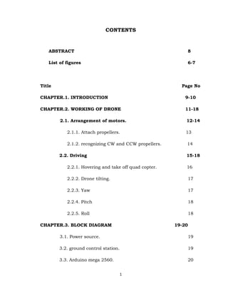
  • 1. 1 CONTENTS ABSTRACT 8 List of figures 6-7 Title Page No CHAPTER.1. INTRODUCTION 9-10 CHAPTER.2. WORKING OF DRONE 11-18 2.1. Arrangement of motors. 12-14 2.1.1. Attach propellers. 13 2.1.2. recognizing CW and CCW propellers. 14 2.2. Driving 15-18 2.2.1. Hovering and take off quad copter. 16 2.2.2. Drone tilting. 17 2.2.3. Yaw 17 2.2.4. Pitch 18 2.2.5. Roll 18 CHAPTER.3. BLOCK DIAGRAM 19-20 3.1. Power source. 19 3.2. ground control station. 19 3.3. Arduino mega 2560. 20
  • 2. 2 3.4. Global position system(GPS). 20 3.5. Electronic speed controller(ESC). 20 3.6. Brush less DC motor(BLDC). 20 CHAPTER.4 COMPONENTES DESCRIPTION 21-36 4.1. Frame. 21-36 4.1.1. Arm of drone. 22 4.2. Motors. 23 4.3. Propellers. 23-24 4.4. Electronic speed controller(ESC). 24-25 4.5. Lithium polymer battery(LiPo). 25-32 4.5.1. LiPo battery rating. 24-28 4.5.2. charging of LiPo. 28-32 4.6. On board pilot controller. 33 4.7. Radio transmitter and receiver. 34 4.8. Global position system(GPS). 35 4.9. Power module. 35 4.10. Landing gears. 36 CHAPTER.5. CIRCUIT CONNECTIONS CHAPTER.6. SET UP FOR APM 2.8(ON BORD PILOT CONTROLLER) 38-79 6.1. Features of APM 2.8 40-41
  • 3. 3 6.2. Mission planner software. 41-42 6.2.1. Installing mission planner. 41 6.2.2. Download most recent mission planner. 42 6.2.3. Run the installation utility. 42 6.3. Inner view of APM 2.8 43 6.4. APM 2.8 wiring diagram. 44 6.5. Powering the flight controller. 45-46 6.5.1. connecting the power module(PM) to flight controller.45-46 6.6. Loading firmware into APM 2.8 47-50 6.6.1. Connect controller to computer. 47 6.6.2. Connect to mission planner. 47-48 6.6.3. Install firmware. 48-49 6.6.4. Setup connections. 49-50 6.6.4.1. Troubleshooting. 50 6.7. MANDATORY HARDWARE COFIGURATION. 51-53 6.7.1. Frame type configuration in mission planner. 51-52 6.7.2. Compass calibration. 52-54 6.7.2.1. on board compass live calibration. 53 6.8 Radio calibration. 54-60 6.8.1. Transmitter configuration. 54 6.8.2. Channel mapping. 56
  • 4. 4 6.8.3. preconditions. 56 6.8.4. Center trims. 56 6.8.5. Connect auto pilot and turn on Receiver. 56-57 6.8.6. calibration steps. 58 6.9. Accelerometer calibration in mission planner. 61-63 6.9.1. Calibration steps. 61 6.10. RC Transmitter flight mode configuration. 64 6.10.1 flight mode configuration. 64 6.11. Electronic speed controller(ESC) calibration. 65-69 6.11.1. About electronic speed controller(ESC) calibration. 65 6.11.2. Waring for electronic speed controller(ESC). 66 6.11.3. All at one calibration. 67-69 6.12. First flight with quad copter. 70 6.12.1. Flight mode. 70 6.13. Pre-Arm safety check. 71 6.13.1. Recognizing which Pre-Arm check. 71 6.13.2. Failure message when drone ready to fly. 71-75 6.14. Disable the Pre-Arm safety check. 75 6.15. Arming the motors. 76-77 6.16. Disarming the motors. 77 6.17. Tips for new pilots. 77-78
  • 5. 5 6.17.1. First flight. 77-78 6.17.2. Tips for your first flight. 78 6.18. Waring about low battery. 78-79 CHAPTER.7. CONCLUSION 80-81 7.1. Future of drone 80-81 CHAPTER.8. BIBILOGRAPHY 82
  • 6. 6 LIST OF FIGURES 1. Body of drone (Fig.1.1) 2. Rotation of motors (Fig.2. (a)) 3. Frame type and motors setup (Fig.2.1. (a), Fig.2.1. (b)) 4. Attach propellers (Fig.2.1.1. (a)) 5. Recognizing of propels (Fig.2.1.1. (b)) 6. Placing of motors on H and X shape frame (Fig.2.2. (a)) 7. Hovering and take-off (Fig.2.2.1. (a)) 8. Tilting (Fig.2.2.2. (a)) 9. Yaw (Fig.2.2.3. (a)) 10. Pitch (Fig.2.4. (a)) 11. Roll (Fig.2.2.5. (a)) 12. Block diagram (Fig.3. (a)) 13. Distribution board (Fig.4.1. (a)) 14. Arm of drone (Fig.4.1.1. (a)) 15. BLDC motor (Fig.4.2. (a)) 16. Propellers (Fig.4.3. (a)) 17. Electronic speed controller (ECS) (Fig.4.4. (a)) 18. LiPo battery (Fig.4.5. (a)) 19. Rating of LiPo battery (Fig.4.5.1. (a)) 20. On board pilot controller (Fig.4.6. (a), (Fig.4.6. (b)) 21. Transmitter and receiver (Fig.4.7. (a)) 22. Global position system(GPS) (Fig.4.8. (a)) 23. Power module(PM) (Fig.4.9. (a)) 24. Landing gears (Fig.4.10. (a)) 25. Circuit connections of drone (Fig.5. (a)) 26. Setup for APM 2.8 (Fig.6. (a)) 27. APM 2.8 protection packing (Fig.6. (b)) 28. APM Firmware (Fig.6.1. (a)) 29. APM mission planner software (Fig.6.2. (a)) 30. Run and installation utility (Fig.2.2. (a)) 31. Inner view of APM 2.8 (Fig.6.3. (a))
  • 7. 7 32. APM wring diagram (Fig.6.4. (a)) 33. Powering to flight controller (Fig.6.5. (a)) 34. Power module connection (Fig.6.5.1. (a), (Fig.6.5.1. (b)) 35. Connect flight controller to computer (Fig.6.6.1. (a)) 36. Connect to mission planner (Fig.6.6.2. (a)) 37. Mission planner firmware install screen (Fig.6.6.3. (a)) 38. APM USB connection (Fig.6.6.4. (a)) 39. Connection using 3DR radio (Fig.6.6.4. (b), (c), (d)) 40. Select frame type (Fig.6.7.1. (a)) 41. Compass calibration (Fig.6.7.2. (a)) 42. Compass live calibration (Fig.6.7.2. (b)) 43. Transmitter mode 1 (Fig.6.8.1. (a)) 44. Transmitter mode 2 (Fig.6.8.1. (b)) 45. Radio Calibration screen (Fig.6.8.5. (a)) 46. Radio calibration is done (Fig.6.8.6. (a)) 47. Result of radio channel ranging (Fig.6.8.6. (b)) 48. Final result of radio channels (Fig.6.8.6. (c)) 49. Calibrate acceleration (Fig.6.9.1. (a)) 50. Accelerometer Calibration Positions (Fig.6.9.1. (b)) 51. Accele calibration is done (Fig.6.9.1. (c)) 52. Calibration successful (Fig.6.9.1. (c)) 53. Flight mode screen (Fig.6.10.1. (a)) 54. Waring for ESC calibration (Fig.6.11.2. (a)) 55. All ESC at once calibration (Fig.6.11.3. (a), (b), (c), (d)) 56. Accelerometer and gyro heck (Fig.6.13.1. (a)) 57. Disabling the Pre-arm safety check (Fig.6.14. (a)) 58. Our drone flying photo (Fig.7. (a))
  • 8. 8 ABSTRACT A quadcopter can achieve vertical flight in a stable manner and used to monitor or collect data in a specific region such as Loading a mass. The goal of this project is to build, modify, and improve an existing quadcopter kit to obtain stable flight, gather and store GPS data, and perform auto commands, such as auto-landing. Technological advances have reduced the cost and increase the performance of the low power microcontrollers that allowed the general public to develop their own quadcopter. The project used an Aero quad quadcopter kit that included a frame, motors, electronic speed controllers, Arduino Mega development board, and sensor boards and used with the provided Aero quad software. Batteries, a transmitter, a receiver, a GPS module was interfaced with the kit. The aero quad software was modified to properly interface the components with the quadcopter kit. Individual components were tested and verified to work properly. Calibration and tuning of the PID controller was done to obtain proper stabilization on each axis using custom PID test benches. Currently, the quadcopter can properly stabilize itself, determine its GPS location, and store log data. Most of the goals in this project have been achieved, resulting in a stable and pilotable quadcopter. The goal of this project is to design and build an autonomous quadcopter from scratch. This means going through the process of researching previous models, performing calculations, purchasing individual parts, testing those parts, designing the final product, designing an APM2.8 based controllers, and finally fitting everything together. All this is to be done with the minimum amount of outside help we can manage (i.e. not using pre-determined code, not buying a boxed set of materials). After deciding how big we wanted our quadcopter to be and purchasing the appropriate parts there were four primary design steps on the way to the final product.
  • 9. 9 CHAPTER.1 INTRODUCTION Drone is also called as UAV (Unmanned aerial vehicle). Which is having on board flight controller on vehicle. Quad-copter(Drone) is a device with an intense mixture of Electronics, Mechanical and mainly on principle of Aviation. A quad copter, also called a quadrotor helicopter or quad rotor is a multirotor helicopter that is lifted and propelled by four rotors. Quad copters are classified as rotorcraft, as opposed to fixed-wing aircraft, because their lift is generated by a set of rotors (vertically oriented propellers). Quad copters differ from conventional helicopters use rotors which are able to vary the pitch of their blades dynamically as they move around the rotor hub. In the early days of flight, quad copters (then referred to either as 'quad rotors' or 'helicopters') were seen as possible solutions to some of the persistent problems in vertical flight; torque- induced control issues (as well as efficiency issues originating from the tail rotor, which generates no useful lift) can be eliminated by counter- rotation and the relatively short blades are much easier to construct. These vehicles were among the first successful heavier-than-air vertical take-off and landing (VTOL)vehicles. A Drone or Quadcopter is a Vehicles have large potential for performing tasks that are dangerous or very costly for humans. Examples are the inspection of high structures, humanitarian purposes or search-and-rescue missions. One specific type of Drone is becoming increasingly more popular lately the quadcopter. When visiting large events or parties, professional quadcopters can be seen that are used to capture video for promotional or surveillance purposes. Recreational use is increasing as well for less than 50 Euros a small remote controlled quadcopter can be bought to fly around in your living room or garden. In these situations, the quadcopter is usually in free flight. There is no physical contact between the surroundings and the quad copter and no cooperation between the quadcopters If would have the capabilities to collaborate the number of possibilities grows even further. For example, a group of Drone would be able to efficiently and
  • 10. 10 autonomously search a missing person in a large area by sharing data between. Or, the combined load capacity of a group of quad copters can be used to deliver medicine in remote areas. This bachelor thesis focuses on the use of a commercially available quadcopter platform, the. Drone, to perform a task that requires physical collaboration and interaction: moving a mass. In this way a clear interaction between the quadcopters and their surroundings is present. As preliminary step towards the view of collaborating aerial robots the choice was made to perform this task in an indoor scenario where position feedback is present. Starting off with position control, additional controller logic can be implemented to counteract the forces imposed by a mass connected to the quadcopter. The choice is made for the Drone, a generalized approach is chosen where possible to encourage reuse of this research’s outcome and deliverables. Fig.1.1 A helicopter is a flying vehicle which uses rapidly spinning rotors to push air downwards, thus creating a thrust force keeping the helicopter aloft. Conventional helicopters have two rotors. These can be arranged as two coplanar rotors both providing upwards thrust, but spinning in opposite directions (in order to balance the torques exerted upon the body of the helicopter). see above Fig1.1
  • 11. 11 CHAPTER.2 WORKING OF DRONE(QURDCOPTER) Working principle of quadcopter is mainly consisting of increase and decrease the speed of the motors, to drive the quadcopter(drone). A quadrotor hovers or adjusts its altitude by applying equal thrust to all four rotors. Rotation of motors are shown in Fig.2.a Quadcopters generally use two pairs of identical fixed pitched propellers, two clockwise (CW) and two counter-clockwise (CCW). These uses independent variation of the speed of each rotor to achieve control. By changing the speed of each rotor it is possible to specifically generate a desired total thrust; to locate for the center of thrust both laterally and longitudinally and to create a desired total torque, or turning force. Fig.2. (a)
  • 12. 12 2.1 ARRANGEMENT OF MOTORS The sections below show motor order for each frame type (the numbers indicates the connected autopilot output pin) and the propeller direction (clockwise (CW) motors are shown in green and take pusher propellers, counterclockwise motors (CCW) are shown in blue and take puller propellers. Propeller Use the diagram for your frame type, and wire the motors as shown in bellow Fig.2.1. (a) and Fig.2.1. (b). Legend for motor-order diagrams Quad copter Fig.2.1. (a) Place motors on quad copter frame any model. But, will place all motors are equal distance from a center point, it is like Triangle, square, hex, etc. There is alternating arrangement of motors on drone. Use Fig 2.1. (b) is acceptable model for to build drone frame.
  • 13. 13 Fig.2.1. (b) 2.1.1 Attach propellers Find your frame in the motor order diagrams above. Clockwise motors are shown in green, marked CW, and take pusher propellers. Counterclockwise motors are shown in blue, marked CCW, and take puller propellers. Use the Fig.2.1. (a) for your frame type, and attach propellers to your vehicle as shown. For copters, attach propellers with the writing facing towards the sky. For more information on recognizing the different types of propellers, see in bellow Fig 2.1.1. (a) Fig.2.1.1. (a)
  • 14. 14 Recognizing clockwise and counterclockwise propellers The Fig.2.1.1. (b) bellow show two types of propellers: clockwise (called pushers) and counterclockwise (called pullers). Pusher propellers are often marked with a P. However not all propellers are marked and both types are often available in either rotational direction. Therefore, it is most reliable to recognize the correct propeller type by its shape as shown below. Reminder that the propellers below have the edge with the shallow consistent curve at the leading edge in direction of rotation and the more radical scalloped (and usually thinner edge) as the trailing edge. You can use these features to recognize propellers of the correct direction of rotation. Recognize of propellers are shown in Fig.2.1.1. (b). Fig.2.1.1. (b) To arrange propellers on motors like Fig.2.2. (b), then controlling of drone (quad copter) will easy. If all motors are rotating single direction the vehicle will not controllable. The force which is generated by one direction rotating motors will be compensating by the other direction rotating motor’s force, the at this time drone is stable, easy to control and it not dangers to environmental.
  • 15. 15 2.2. DRIVING OF DRONE(QUADCOPTER) Fig.2.2. (a) This is quadcopter placed upon a H or X shaped frame. In this above Fig.2.2. (a) we using quad copter will be placing of motors like H shape as and X shape. Both two shapes are used for drone motors. Four motors A, B, C, and d are placed equal distance from the center of its body shape. If motors of drone con not place according into Fig.2.2. (a) the forces generating by motors are not compensating each. This result drone (quad copter) control is very complicated as well as it is cause to injure to living being which are in the field.
  • 16. 16 2.2.1 Hovering and take - off quadcopter(drone) For hovering a balance of forces is needed. If we want the quad-copter to hover, SUM(Fi) must be equal m•g. To move the quad-copter climb/decline the speed of every motor is increased/decreased. ➢ SUM(Fi) > m•g <=> climb ➢ SUM(Fi) = m•g <=> hover ➢ SUM(Fi) < m•g <=> decline See Below Fig.2.2.1.1 Fig.2.2.1. (a)
  • 17. 17 2.2.2. Quadcopter(drone)tilting Now let take a look on what is happening when we tilt the quad- copter. For simplification, only two of the four rotors are shown. We see that the force is divided in two different parts. FL1 and FL2 are the part of the force used to lift the quad-copter. FT1and FT2 represents the part used for the translation. It is obvious that the lift part becomes smaller with increasing φ. Tilting of drone is shown in Fig.2.2.2. (a). Fig.2.2.2. (a) 2.2.3 Yaw Yaw is the deviation/Rotating the head of the quadcopter either to right or left, Yaw can be controlled through the throttle stick, also called rudder, making it to rotate either to the left or right. (Or) Yaw is simply defined as the rotation of a UAV with respect to the center axis. If you were looking down on a drone from above, yaw refers to the movement of the drone clockwise or counter clockwise. yaw is shown in Fig.2.2.3. (a). Fig.2.2.3. (a)
  • 18. 18 2.2.4 Pitch Pitch is the movement of quadcopter either forward and backward. Forward Pitch is achieved by pushing the aileron stick forward, which makes the quadcopter tilt and move forward, away from you. Backward pitch is achieved by moving the aileron stick backwards(towards you), making the quadcopter, come closer to us. Pitch of drone is shown in Fig.2.2.4. (a). Fig.2.4. (a) 2.2.5 ROLL Roll is making the quadcopter fly sideward, either to left or right. Roll is controlled with the aileron stick, making it move left of right, if you move the aileron stick to the left, the quadcopter will fly left, if you move the aileron stick to right, the quadcopter will fly right. Roll of drone is shown in the Fig..2.5. (a) Fig.2.2.5. (a)
  • 19. 19 CHAPTER.3 BLOCK DIAGRAM Fig.3. (a) Above Fig.3. a is shown the block diagram of drone 3.1 POWER SOURCE In this drone block diagram, we are LiPo battery as power source. It is give power to directly to ESC (electronic speed controller). 3.2 GOUND CONTROL STATION Ground control station is a control strategy for control of drone as well as to monitor the drone through computer and mobile phone etc. Normally for this ground control station we are using 3DR radio telemetry. This also use for to set up flight planning, to set PID values when drone in air, to change radio channel when drone in air etc.
  • 20. 20 3.3 ARDUINO MEGA 2560 This is an on-board pilot which is monitoring all operation which are going in drone system. This contain bellow meters 1. Accelerometer: This is use to find tilting of vehicle. It will give the vehicle’s tilting angle to Arduino Mega 2560.Taking this information the controller will generate the signals and give those to ESC (electronic speed controller). 2. Gyro meter: Gyro meter is for to fly the vehicle with respect to our input. If any other physical forces are acting on vehicle the Gyro meter will minimized those physical forces. It is used for navigation of drone. 3. Magneto meter: Is used for orientation, navigation of drone. 4. Barometer: It can provide the atmospheric pressure to controller. Arduino Mega 2560 will collect data from all meters, I will check it is comfortable to fly or not. If the environment is good all meters are working proper way, the Arduino Mega 2560 will response to radio signal (arming). 3.4 GPS (global position system) GSP (global position system) it is a hardware which is used to find location of drone. In advance this GPS will use for navigation of a drone. GPS was connected to a 5pin GSP port in APM 2.8. 3.5 ESC (electronic speed controller) This a circuit which is used for to control of brush less DC motor’s speed. ESC are connecting in between distribution board and BLDC motors, and ESC signal wire is connected to APM2.8. 3.6 BLDC (brush less DC motors) Brush less DC motors (BLDC) coupled with propellers are to give thrust to drone which is using to drive the drone in the air. BLDC motors are connected output of ESC.
  • 21. 21 CHAPTER.4 COMPONENTES DESCRIPTION 4.1 FRAME Just as important as good electronics, multi-rotors depend on sturdy, lightweight hulls for mounting components. There are countless frame designs of varying shapes, dimensions, and materials. Stiffer frames confer better flight characteristics, since less warping and bending can occur. If a frame is too brittle, though, your inevitable crashes will result in more frequent repair sessions. Frames need to be both strong and stiff, whilst being light enough to hop around in the sky with ease. One of the most common materials for multi-rotor frames is carbon fiber. A great many of its physical properties are perfectly suited to the hobby. The only catch is that carbon fiber is known to block radio signals, which is obviously not ideal for a hobby that depends on multiple transmissions. It can be used though, and is often. Just be aware that blocked signals are a possibility. Frames can also be built at home using aluminum or balsa sheet. But results will vary from manufactured frames, both aesthetically and in terms of flight attributes. Common is the integration of power distribution circuits into the frame plates. Battery connections are soldered directly to pads built into the material, and power can be tapped at other solder points without the need for extensive, messy wiring. Although by no means essential, a clean setup is satisfying and less likely to fail, making power-distributing frames a worthy investment. Frame with distribution board is shown in Fig.4.1. (a).
  • 22. 22 Fig.4.1. (a) 4.1.1 Arms Arms can be built at home using aluminum or hard plastic tubing. However, for many hobbyists, it's preferable to go with pre-built arms. These components are relatively cheap and easy to replace. Therefore, they're generally considered a pre-determined breaking point. In the event of a crash, the arms should be the first to give, preventing damage to motors or expensive electronics on the frame. You actually want them to be a bit brittle, particularly on a heavier, crash-prone quad. Quad copter arm shown in Fig.4.1.1. (a) Fig.4.1.1. (a)
  • 23. 23 4.2 MOTORS 1000Kv Brushless Quadcopter Motors is a Brushless DC electric motor (BLDC motors) also known as electronically commutated motors (ECMs, EC motors) are synchronous motors that are powered by a DC electric source via an integrated inverter switching power supply, which produces an AC electric signal to drive the motor. In this context, AC, alternating current, does not imply a sinusoidal waveform, but rather a bi-directional current with no restriction on waveform. The motors chosen should meet the following specifications: ▪ Lightweight. ▪ High speed and torque. ▪ PWM speed controlled. We chose A2212/13T (1000KV) brushless motor. Fig.4.2. (a) 4.3 PROPELLER It is a device which converts the rotational motion into thrust. the drone propellers for the quads are small in size and usually made up of plastic material. there are altogether four propellers; two move in the clockwise direction and two moves in the anti-clockwise direction. Propellers are always categorized according to the length and the pitch. Pitch is the distance travelled by drone in one single prop rotation. The propellers with lower pitches produce more torque, therefore, the motor can operate on less current. In case if we are using a high pitch prop, then more air will get displaced and this will result in a commotion. Due to this, our drone would shake while hovering. Thus, a lower pitch propeller we used. Propellers are shown in Fig.4.3. (a).
  • 24. 24 ▪ Dimension: 10X4.7 inch. ▪ 4 propellers. ▪ Directly attached to motor. ▪ 2 each rotating CW and CCW (“pusher "and a “normal"). ▪ Propeller use for to drive the drone(quadcopter). Fig.4.3. (a) 4.4 ELECTRONIC SPEED CONTROLLER (ESC) An electronic speed control or ESC is an electronic circuit with the purpose to vary an electric motor's speed, its direction and possibly also to act as a dynamic brake. ESCs are often used on electrically powered radio controlled models, with the variety most often used for brushless motors essentially providing an electronically generated three-phase electric power low voltage source of energy for the motor. ESC is shown in Fig.4.4. (a). ▪ The motor speed is set by the ESC in response to a pulse width modulated control signal.
  • 25. 25 ▪ The motor speed is then proportional to the root-mean-square (RMS) value of the armature voltage. Fig.4.4. (a). 4.5 LiPo BATTERY Properties ▪ Lightweight. ▪ High discharging current and capacity. ▪ low internal resistance. ▪ long working time. Fig.4.5. (a) Lithium Polymer (LiPo) are achieve these characteristics 4.5.1 LiPo battery ratings
  • 26. 26 LiPo battery basics, time to get into the main topics at hand. First are ratings, specifically voltage and capacity. These are the two main numbers you will need when going battery shopping. There are a couple others you will also need to know about, but they are arbitrary and not concrete like the first two. bellow Fig.4.5.1. (a) shown the rating of LiPo batteries Fig.4.5.1. (a) 1. Voltage (shown in red in above photo) Unlike conventional NiCad or NiMH battery cells that have a nominal voltage of 1.2 volts per cell, LiPo battery cells have a nominal voltage of 3.7 volts per cell. The benefit here is fewer cells can be used to make up a battery pack and in some cases on smaller micro sized RC aircraft like most toy helicopters or hobby grade micros like the Blade mCX2, or Nano QX, a single 3.7 volt LiPo cell is all that is needed to power the model. Other than the smallest of electric RC models, RC LiPo battery packs will have at least two or more cells hooked up in series to provide higher voltages. For larger RC models that number can be as high as 6 cells and even more for larger birds or HV (high voltage) applications. Here is a list of LiPo RC battery pack voltages with cell counts. If you are wondering what the 1-12S in parenthesis means; it's the way battery manufacturers indicate how my cells hooked in series(S) the battery pack contains. • 3.7 volt battery = 1 cell x 3.7 volts (1S) • 7.4 volt battery = 2 cells x 3.7 volts (2S) • 11.1 volt battery = 3 cells x 3.7 volts (3S) • 14.8 volt battery = 4 cells x 3.7 volts (4S)
  • 27. 27 • 18.5 volt battery = 5 cells x 3.7 volts (5S) • 22.2 volt battery = 6 cells x 3.7 volts (6S) • 29.6 volt battery = 8 cells x 3.7 volts (8S) • 37.0 volt battery = 10 cells x 3.7 volts (10S) • 44.4 volt battery = 12 cells x 3.7 volts (12S) 2. CAPACITY (shown in green) Capacity indicates how much power/energy the battery pack can hold and is indicated in milliamp hours (mAh). This is just a fancy way of saying how much load or drain (measured in milliamps) can be put on the battery for 1 hour at which time the battery will be fully discharged. For example, an RC LiPo battery that is rated at 1000 mAh would be completely discharged in one hour with a 1000 milliamp load placed on it. If this same battery had a 500-milliamp load placed on it, it would take 2 hours to drain down. If the load was increased to around 15,000 milliamps (15 amps); a very common current drain in a 3S powered 450 sized RC helicopter while hovering - the time to drain the battery would be only about 4 minutes. As you can see, for a RC model with that kind of current draw, it would be very advantageous to use a larger capacity battery pack such as a 2000 mAh pack. This larger pack used with a 15-amp draw would double the time to about 8 minutes till the pack was discharged. The main thing to get out of this is if you want more flight time; increase the capacity of your battery pack. Unlike voltage, capacity can be changed around to give you more or less flight time. Naturally because of size & weight restrictions, you have to stay within a certain battery capacity range seeing that the more capacity a battery pack has, the larger and heavier it will be. • Think of increasing the RC LiPo battery capacity similar to putting a larger fuel tank in the RC vehicle. 4. DISCHARGE RATE (shown in yellow) This one is probably the single most over rated & misunderstood of all battery ratings. rate is simply how fast a battery can be discharged safely. Remember that ion exchange thing further up the page? Well the faster the ions can flow from anode to cathode in a battery will
  • 28. 28 indicate the discharge rate. In the RC LiPo battery world it is called the “C” rating. What does it mean? Well Capacity begins with “C” so that should give you a pretty good idea. A battery with a discharge rating of 10C would mean you could theoretically & safely discharge it at a rate 10 times more than the capacity of the pack, a 15C pack = 15 times more, a 20C pack = 20 times more, and so on. Using our 1000 mAh battery as an example; if it has a 20C discharge rating, that would mean you could pull a maximum sustained load up to 20,000 milliamps or 20 amps off that battery (20 x 1000 milliamps = 20,000 milliamps or 20 amps). From a purely theoretical time stand point, this equals 333 mAh of draw per minute so the 1000 mAh pack would be completely exhausted in about 3 minutes if it's exposed to the maximum rated 20C discharge rate the entire time. Calculation as follows: 20,000 mA divided by 60 minutes = 333 mAh which is then divided into the 1000 mAh capacity of the pack giving us 3.00 minutes). Most RC LiPo Battery packs will show the continuous C rating and usually a maximum burst C rating as well. A burst rating indicates the battery discharge rate for short bursts (a few seconds maximum) of extended power. An example might be something like "Discharge rate = 25C Continuous/50C Bursts". The higher the C rating, usually the more expensive and even slightly heavier the battery gets. This is where you can save some money, and maybe even a little weight. Getting an extremely high discharge rated pack when there is no way you could possibly pull the full amount of power is not required but it won't hurt either. The most important thing is you can't go with too low a discharge C rating or you will damage your battery and possibly your ESC (electronic speed control). 4.5.2 Charging LiPo batteries Charging RC LiPo Batteries is a topic in itself. LiPo, Li Ion, and Li Fe batteries obviously have some very different characteristics from conventional RC rechargeable battery types. Therefore, charging them correctly with a charger specifically designed for lithium chemistry batteries is critical to both the lifespan of the battery pack, and your safety. A 3.7 volt RC LiPo battery cell is 100% charged when it reaches 4.2 volts. Charging it past that will shorten life substantially. In fact, the cell
  • 29. 29 phone industry did a study looking at the effect of LiPo fully charged voltages in relation to cycle life. These tests were done under ideal laboratory conditions and of course the 80% depth of discharge rule was obeyed! Here are the results: • Charge to 4.1V gave over 2000 cycles. • Charge to 4.2V gave about 500 cycles. • Charge to 4.3V gave under 100 cycles. • Charge to 4.4V gave less than 5 cycles. Folks in the RC world have reported similar results and one ongoing test seems to indicate if you set your maximum charge voltage to 4.15 volts per cell (if your computerized charge gives you that option), you should be able to get about 800 cycles (again if all the other LiPo usage rules are religiously obeyed). More and more people are considering this 4.15 termination voltage the "sweet spot" for both performance and cycle life for RC usage. Most RC chargers don't give you that ability, but if yours does, you may want to consider it. One caveat to this I should mention are the new generation of "high voltage" LiPo cells. There are a few manufacturers that are producing LiPo cells that can handle as high as 4.35 volts and maintain a 500 cycle life. No matter what your maximum charge termination voltage is, keeping each cell in the RC LiPo battery pack at that same voltage is another important rule to understand once I start talking about Balancing RC LiPo batteries, so keep that in the back of your head for right now. It is critical that you use a charger specified for LiPo batteries and select the correct voltage or cell count when charging your RC LiPo batteries if you are using a computerized charger. If you have a 2 cell (2S) pack you must select 7.4 volts or 2 cells on your charger. If you selected 11.1V (a 3S pack) by mistake and tried to charge your 2S pack, the pack will be destroyed and most likely catch fire. Luckily, all the better computerized chargers out there these days will warn you if you selected the wrong cell count. All LiPo battery chargers will use the constant current / constant voltage charging method (cc/cv). All this means is that a constant current is applied to the battery during the first part of the charge cycle. As the battery voltage closes in on the 100% charge voltage, the charger will automatically start reducing the charge current and then apply a constant voltage for the remaining phase of the charge cycle. The charger will stop charging when the 100% charge voltage of the battery pack equalizes with charger’s constant voltage setting (4.2 volts per cell) at this time, the charge cycle is completed. Going past that to 4.3 volts will shorten battery life substantially as we have already seen.
  • 30. 30 LiPo Battery Charging Current Selecting the correct charge current is also critical when charging RC LiPo battery packs. The golden rule here remains to be "never charge a LiPo, LiIon, or LiFe pack greater than 1 times its capacity (1C)." For example, a 2000 mAh pack, would be charged at a maximum charge current of 2000 mA or 2.0 Amps. Going higher will shorten the life of the pack. Moreover, if you choose a charge rate significantly higher than the 1C value, the battery will heat up and could puff up. Higher than 1C charge rates... Most LiPo experts say you can safely charge at a 2C or even 3C rate on quality packs that have a discharge rating of at least 20C or more and have low internal resistances safely, but it will reduce LiPo life. Even though there are more and more LiPo packs showing up stating 2C, 3C, 4C and even 5C charge rates; this is just indicating it's still safe to charge at those rates and not risk thermal runaway within the battery; but it really has nothing to do with actual battery life. The simple fact is constantly charging any LiPo over 1C will have an impact on its life expectancy. I will charge at higher than 1C rates on occasion when I'm in a rush to get out to the field or want to get into the air again quickly; but I always try to charge at 1C or lower rates most of the time. It all boils down to speed vs. life and your budget. If you don't mind taking some life out of your packs in favour of getting back in the air or out on the track ASAP, then charging at higher C rates might be a viable compromise for your particular needs. I would also strongly recommend never charging over 1C if the ambient air temperature (and the pack) is over 30C (about 90F). The seven main things that shorten LiPo battery life are: 1. HEAT 2. LEAVING A LIPO FULLY CHARGED FOR SEVERAL DAYS 3. OVER DISCHARGING (voltage & current) 4. OVER CHARGING (voltage & current) 5. INADEQUATE BALANCING 6. IMPROPER STORAGE VOLTAGE (more on that shortly) 7. PHYSICAL DAMAGE (dropping, over tightening straps, prying cells apart, using too much/too strong Velcro etc.)
  • 31. 31 Here are my 5 simple LiPo Charging Safety Tips that I follow • I usually charge all my larger multi celled LiPo’s directly on the concrete floor in the shop well away from any combustibles. • I always wait at least 15 minutes after using a LiPo to let it cool down before charging it. This prolongs the life of the LiPo and prevents possible overheating and damage. • I never ever leave the house (preferably the room) when charging LiPo’s. • I store all my LiPo's in a metal tool chest in various compartments so if one goes up in smoke it hopefully won't take them all. Ammo boxes are also an excellent choice. I don't trust LiPo sacks or bags at all! They are a complete waste of money for all but small packs IMO. You can pick up surplus ammo boxes for less money and they offer superior protection. • Lastly – I purchased an inexpensive smoke detector that I have mounted above my charging area & storage chest so in the unlikely event a pack bursts during a charge cycle or while in storage, the smoke detector will sound and I will be alerted. I also have a small fire extinguisher mounted on the wall in my workshop for any fire that may occur, not just a LiPo fire. This may seem excessive, chances are it is... but after watching the video below, I feel these are worthwhile precautions. 4.5.3 RC LiPo Battery Storage A LiPo cell that drops below 3 volts under load (about 3.6V open circuit voltage) is almost always & irreversibly damaged. It will have reduced capacity or total inability to accept a charge due to cell oxidation. If your batteries are stored for any period of time after you use them at close to that magic 3.6 volt per cell number, you risk irreversible damage. As batteries sit, they will naturally self-discharge. LiPo’s are actually very good in this respect and self-discharge much slower than most other rechargeable battery types, but they still do lose capacity as they sit (about 1% per month). If you leave them for a number of weeks or months in a near fully discharged state, chances are they may be irreversibly damaged as the cells oxidize. You must store them charged, but not fully charged either – that will also degrade/oxidize the cell matrix. Fully charged LiPo batteries are not happy and must be used soon after they are fully charged. They are very much like F1 cars sitting on the grid!
  • 32. 32 Basically, the speed at which a LiPo pack ages (during storage) is based on both storage temperature and state of charge. You are likely okay to store a fully charged RC LiPo battery at room temperature for up to 2 days without doing too much damage. Never ever store a LiPo in a hot car fully charged for an extended time, that will certainly cause damage (puffed and may even vent) as I explained earlier, but it's worth repeating. For optimum battery life, store your RC LiPo batteries in a cool room if possible (slows down the chemical reaction) at about a 40-60% charged state. That equates to around 3.85 volts per cell (open terminal resting voltage). The actual storage range is likely a little broader than this (I have heard some say numbers as high as 30-80% is fine, but since computerized chargers set the storage charge at 50% (3.85 volts per cell) that's recommend and what i follow myself. You can actually extend the fully charged storage time from a couple days to weeks by storing your batteries in the fridge (not freezer) close to 0 degrees Celsius (32F); again, that helps slow down the chemical reaction that oxidizes the cathode in the cells. I have started doing this with my smaller packs seeing that I will often find myself wanting to go flying little micros with little lead time and it is very convenient having packs already fully charged. If you do store your fully charged LiPo's in the fridge, pack them in a zip-lock freezer bag and squeeze out all the air before sealing the bag. This will prevent condensation forming on the battery packs when you take them out of the fridge as they warm up. You should allow the LiPo pack to warm up after removing from the fridge before using it of course. Small micro LiPo's warm quickly, big packs don't. This is why I only use the "fully charged cold storage" method with micro packs.
  • 33. 33 4.6 ON BOARD PILOT CONTROLLER ArduPilot (APM 2.8) Fig.4.6. (a) • Collects sensor data. • Receives control commands. • Calculates orientation. • Control motor speed. We use ArduPilot (APM 2.8) in our project Fig.4.6. (b)
  • 34. 34 4.7 TRANSMITTER AND RECIVER • This wireless receiver provides a simple, straight-forward receiver for all of low-cost wireless project. • Features: ▪ 2.4 GHz ▪ 1000 m Range transmitter shown in Fig.4.7. (a) Fig.4.7. (a) For the drone (quad copter) minimum 6 channel transmitter and receiver require. Using this transmitter will allocate the driving of drone follow. Channel number Channel function 1 Aileron 2 Elevator 3 Thrust 4 Rudder 5 Flight 6 PID tuning for clean flight
  • 35. 35 4.8 Global Position System(GPS) A drone with GPS and autopilot system including camera gives you plenty of aerial options. As well as flying its programmed route. GPS will also use to tracing and navigation of the drone. For this application, we want to use an efficient signal providing GPS module. Now a days uBlox 7M is most suitable for tracing and navigation of drone. UBlox 7M is shown in Fig.4.8. (a). Fig.4.8. (a) 4.9. POWER MODULE(PM) In APM 2.8 we want provide a constant voltage to board for operating properly as well as to monitoring of board voltage and current.so we are using power module(PM). bellow Fig.4.9. a is shown the power module picture. Fig.4.9. (a)
  • 36. 36 4.10 LANDING GEARS Usually the landing gears use for landing the drone without any damage. Another think when drone in take-off landing gears are used for to compensating ground interface on sensors which are located in on board pilot controller (APM 2.8). We are using these landing gears in shown in Fig.4.10. (a). Fig.4.10. (a)
  • 37. 37 CHAPTER.5 CIRCUIT CONNECTIONS Fig.5. (a) Connections made as per Fig.5. a diagram Then follow the next bellow APM 2.8 setup
  • 38. 38 CHAPTER.6 SETUP FOR APM 2.8 Fig.6. (a) The APM 2.8 board requires no assembly, and is ready for firmware. You have a choice of side or top entry pin configuration, in order to accommodate a variety of installations. You’ll see this option when you order.
  • 39. 39 APM 2.8 Fig.6. (b) Above Fig 6. (b) is shown the APM 2.8 flight controller protection packing. APM 2.8 will contain some of meters which are used to control the vehicle when the it is in air, if don not provide this type of protection to APM 2.8 the drone (quad copter) may be chance to misbehaver with us or irresponsive to our controllers. If there is poor protection of APM 2.8 the affected parts are in inner view of APM2.8 Fig6.3. (a).
  • 40. 40 6.1. Features APM 2.8 1.APM 2.8 is a revision of the APM that makes use of an internal compass. 2.The APM 2.8 has on board compass, and is optimized for vehicles where the compass should be placed as far from power and motor sources as possible to avoid magnetic interference. 3.APM 2.8 is designed to be used with the 3DR GPS uBlox 7M with Compass module. 4.The GPS/Compass module may be mounted further from noise sources than the APM itself. 5.APM 2.8 requires a GPS unit with an on-board compass for full autonomy. 6.For information on installing a 3DR GPS uBlox 7M with Compass. APM FIRMWARE Fig.6.1. (a)
  • 41. 41 The firmware is the code that runs on the board. There are many different firmware bases to choose from. Depending on what code you load, you can use the APM to control fixed wing aircraft, multi rotors, helicopters and also ground rovers. 6.2 MISSION PLANNER SOFTWARE Fig.6.2. (a) APM software is the program that runs on your PC, it is used to load the firmware, and change the settings on your APM board. You can also use this software to plan missions and monitor your drone on the map. 6.2.1 Installing Mission Planner Mission Planner is free, open source software available for Windows. These instructions will guide you through installing Mission Planner on your ground station computer.
  • 42. 42 6.2.2 Download the most recent Mission Planner installer Download mission planner from hear: - firmware.ardupilot.org/Tools/MissionPlanner/MissionPlanner-latest.msi 6.2.3 Run the installation utility Open the Microsoft installer file (.msi) and select Run to run the installation utility. Fig.2.3. (a) Follow the instructions to complete the setup process. The installation utility will automatically install any necessary software drivers. If you receive a DirectX installation error, please update your DirectX plug-in from this link http://www.microsoft.com/en- us/download/details.aspx?id=35
  • 43. 43 6.3. INNER VIEW OF APM 2.8 Fig.6.3. (a) This (Fig6.3. (a)) is the inner view APM 2.8. It is shown the all the meters, microcontroller, connections pins, Barometer and accelerometer etc. All parts which are shown in Fig 6.3. (3) are used for to fly the drone in air and to communicate the drone and to drive the drone. These meters are used for collect the data of drone at each second of, for each flight time. These can give stable flight.
  • 44. 44 6.4 APM WIRING DIAGRAM The diagram below is an overview of how an APM2 can be connected to a receiver, ESC, GPS and even a camera gimbal. Fig.6.4. (a) Above Fig 6.4. (a) shown that wiring diagram of drone (quad copter). In this Fig.6.4. (a) electronic speed control (ESC) are connected in between motors, APM 2.8 and LiPo battery. Electronic speed controller’s signal pins are connecting at APM 2.8 Output side. Radio channel receiver is connecting input side of APM 2.8 flight controller. Extra tools which are used for navigation of drone there are connect their places according into APM 2.8 marking. APM 2.8 top side there is indications for different connections, should follow the those marking. If there is any wrong connection APM 2.8 do not response to any of supply (for USB and LiPo).
  • 45. 45 6.5 POWERING THE FLIGHT CONTROLLER The easiest way to power the APM2.x is using a 3DR Power Module with a LiPo battery. To wire a power module, connect the red-and-black two wire cable on the power module to the PDB red and black two-wire. Connect the power module to the APM PM port using a 6-position cable. Connect the PDB multi-wire cable to APM Output Signal pins with the M1 wire connecting to the signal pin labeled 1, M6 and signal pin 6, etc. See the bellow (Fig.6.5. a) for additional detail. Fig.6.5. a 6.5.1 Connecting the PM (power module) to a flight controller board Fig.6.5.1. (a)
  • 46. 46 Fig.6.5.1. (b) APM2.8 Power Port Your battery connects to the Power Module’s male connector, and its female connector plugs into your ESC or Power Distribution Board. Above Fig.6.5.1. (b) shown the connection of power module to APM 2.8. Powering the APM 2.8 should follow some points 1. Turn on transmitter. 2. Connection LiPo battery to power module. 3. Do not connect 6-pos connector to APM 2.8 Fig.6.5.1. (b). 4. Connect power module and drone distribution board. 5. Now connect the 6-pos connector to APM 2.8 which shown in Fig.6.5. (b). 6. Now the drone (quad copter) is in ON position.
  • 47. 47 6.6 LOADING FIRMWARE INTO APM 2.8 6.6.1 Connect controller to computer Once you’ve installed the Mission Planner onto your computer, connect the autopilot board to your computer using the micro USB cable as shown below. Use a direct USB port on your computer (not a USB hub). Fig.6.6.1. (a) PX4 USB Connection Windows should automatically detect and install the correct driver software. 6.6.2 Connect to mission planner Open the Mission Planner and select the COM port drop-down on the upper-right corner of the screen (near the Connect button). Select AUTO
  • 48. 48 or the specific port for your board (Arduino Mega 2560). Set the Baud rate to 115200 as shown Fig.6.6.2 (a). Don’t hit Connect just yet. Fig.6.6.2. (a) 6.6.3 Install firmware On the Mission Planner’s Initial Setup| Install Firmware screen select the appropriate icon that matches your frame (i.e. Quad, Hex). Answer Yes when it asks you “Are you sure?”. Fig.6.6.3. (a) Mission Planner: Install Firmware Screen After the Mission Planner detects which board you are using (i.e. APM 2.8) it will ask you to unplug the board, plug it back in and then press
  • 49. 49 OK within a few seconds (during this brief period the bootloader accepts requests to upload new firmware). Testing You can test the firmware is basically working by switching to the Mission Planner Flight Data screen and pressing the Connect button. The HUD should update as you tilt the board. 6.6.4 Setting up the connection To establish a connection, you must first choose the communication method/channel you want to use, and then set up the physical hardware and Windows device drivers. You can connect the PC and autopilot using USB cables, Telemetry Radios, Bluetooth, IP connections etc.
  • 50. 50 APM 2.8 USB connection Fig.6.6.4. (a) Fig.6.6.4. (b) Connection using SiK 3DR Radio On Mission Planner, the connection and data rate are set up using the drop-down boxes in the upper right portion of the screen. Fig.6.6.4. (c) Once you’ve attached the USB or Telemetry Radio, Windows will automatically assign your autopilot a COM port number, and that will show in the drop-down menu (the actual number does not matter). The appropriate data rate for the connection is also set (typically the USB connection data rate is 11520 and the radio connection rate is 57600).
  • 51. 51 Select the desired port and data rate and then press the Connect button to connect to the autopilot. After connecting Mission Planner will download parameters from the autopilot and the button will change to connect as shown in Fig.6.6.4. (d). Fig.6.6.4. (d) 6.6.4.1. Troubleshooting If Mission planner is unable to connect: • Check that the correct baud rate is used for the selected method (115200 on USB or 57600 on Radio/Telemetry) • If using a COM port on Windows, check that the connection’s COM port exists in the Windows Device Manager’s list of serial ports. • If using a USB port, try a different physical USB port. • if using a UDP or TCP connection, check that your firewall is not blocking the IP traffic. 6.7 MANDATORY HARDWARE CONFIGURATION As part of first time setup, you’ll need to configure some required hardware components. The linked articles describe the process for selecting frame orientation and configuring the RC transmitter/receiver, compass, and accelerometer using Mission Planner and how to configure the ESCs. 6.7.1 Frame type configuration in mission planner On the Mission Planner ‘s Initial Setup screen select Mandatory Hardware | Frame Type. Select the frame for your copter. The default configuration is X. If you want one of the arms to serve as the exclusive front-facing direction, select the Plus configuration. For Tricopters, Traditional Heli’s and Y6s, the frame type is ignored.
  • 52. 52 Mission Planner: Select Frame Type (Fig.6.7.1. (a)). 6.7.2 Compass calibration Calibration first steps • Under Initial Setup | Mandatory Hardware select Compass. • Select your flight controller configuration to automatically enter the most important configuration information for your board: Mission Planner: Compass Calibration (Fig.6.7.2. (a))
  • 53. 53 6.7.2.1. Onboard calibration (aka (“Live Calibration”) of compass Older versions of ArduPilot rely on the ground station to calculate the compass offsets. To use this older method: • Click the Live Calibration button. A window should pop-up showing you the state of the live calibration. Mission Planner: Live Compass Calibration (Fig.6.7.2. (b)). • The aim is to rotate the vehicle so that the coloured trail hits each of the white dots. One way to do this is to hold the vehicle in the air and rotate it slowly so that each side (front, back, left, right, top and bottom) points down towards the earth for a few seconds in turn. • The calibration will automatically complete when it has data for all the positions. At this point, another window will pop up telling you that it is saving the newly calculated offsets. These are displayed on the main screen below each associated compass.
  • 54. 54 Compass error messages • Compass Health: The compass has not sent a signal for at least half a second. • Compass Variance: In the EKF solution, compass heading disagrees with the heading estimate from other inertial sensors. Clicking the EKF button on the Mission Planner HUD will show the magnitude of the error. • Compass Not Calibrated: The compass needs to be calibrated. • Compass Offsets High: One of your compass offsets exceeds 600, indicating likely magnetic interference. Check for sources of interference and try calibrating again. 6.8 RADIO CONTROL CALIBRATION IN MISSION PLANNER Overview RC transmitters are used to control vehicle movement and orientation. Copter and Plane minimally control throttle, pitch, roll and yaw, while on Rover we just control throttle and roll. Each of these control signals are mapped to transmitter stick/switch(s) and in turn to autopilot channels from the connected receiver. Calibrating each of the transmitter controls/channels is a straightforward process - simply move each of the enabled sticks/switches through their full range and record the maximum and minimum positions. 6.8.1 Transmitter configuration There are two main transmitter configurations: • Mode 1: left stick controls pitch and yaw, the right stick will control throttle and roll. • Mode 2: left stick controls throttle and yaw; the right stick will control pitch and roll.
  • 55. 55 Transmitter (Mode 1): Recommended Channels (Fig.6.8.1. (a)). Transmitter (Mode 2): Recommended Channels (Fig.6.8.1. (b)).
  • 56. 56 6.8.2 Channel mappings • Channel 1: Roll • Channel 2: Pitch • Channel 3: Throttle • Channel 4: Yaw • Channel 5: Flight modes • Channel 6: (Optional) Inflight tuning or camera mount (mapped to transmitter tuning knob) 6.8.3 Preconditions Safety first For safety reasons, you should disconnect the battery and/or remove propellers before preforming radio calibration. 6.8.4. Center trims Centre trims in manual RC mode before preforming RC calibration. If trims are not centered, you may need to do the RC calibration again after you have used the vehicle (this is easy to do at the field). Note: -Trims are centered when a moving vehicle does not change direction/speed/orientation when travelling hands-off with all controls/sticks in neutral positions. If there is any deviation in direction, speed or orientation, adjust the associated servo to compensate. 6.8.5 Connect autopilot and turn on receiver Connect the autopilot via USB and turn on your RC transmitter. Verify that the transmitter is bound to the receiver (the receiver displays a solid green light) and that it is set to use the correct model for your vehicle. Open Mission Planner’s INITIAL SETUP | Mandatory Hardware | Radio Calibration screen. If your RC receiver (Rx) and transmitter (TX) are bound, you should see the green bars move when you move the transmitter sticks.
  • 57. 57 Mission Planner: Radio Calibration Screen (Fig.6.8.5. (a)). Tips: - If the bars are not moving, then check what LED lights the receiver is displaying: • no lights - may indicate that it is incorrectly wired to the autopilot (look for connectors that may have been inserted upside down). • red or a flashing green light - may indicate that your RC transmitter/receiver need be bound (see the manual that came with your RC equipment for instructions). • a solid green light - recheck the autopilot is connected to the Mission Planner and if the bars are still not moving, try clicking on the Calibrate Radio button.
  • 58. 58 6.8.6 Calibration steps 1. Open Mission Planner’s INITIAL SETUP | MANDATORY HARDWARE | Radio Calibration screen. 2. Click on the green Calibrate Radio button in the lower right of the window. Mission Planner will display a prompt to check radio control equipment is on, battery is not connected, and propellers are not attached. Select OK. Select Calibrate Radio and OK to begin calibrating (Fig.6.8.6. a). 3. Move the control sticks and toggle switches on your transmitter to their limits of travel and observe the results on the radio calibration bars. Red lines will appear across the calibration bars to indicate maximum and minimum values:
  • 59. 59 Mission Planner: Input range marked with red lines (Fig.6.8.6. (b)). Tip: - The green bars should move in the same direction as the Transmitter sticks (except for Pitch where the bars move opposite to stick movements - low values are forward, high values are back). If the green bars move in the wrong direction, reverse them using your RC transmitter’s channel- reverse function (see your RC gear’s manual for guidance). you should also calibrate the channel you have selected for controlling vehicle mode, and any other channels you have connected to the autopilot. 4. Select Click when Done when all required channels are set at the minimum and maximum positions. Mission Planner will show a summary of the calibration data. Normal values are around 1100 for minimums and 1900 for maximums.
  • 60. 60 Mission Planner: Radio Calibration Results (Fig.6.8.6. (c)). 5.Turn off your transmitter and disconnect the battery if it was connected.
  • 61. 61 6.9 ACCELEROMETER CALIBRATION IN MISSION PLANNER 6.9.1 CALIBRATION STEPS 1. Under Initial Setup | Mandatory Hardware, select Accel Calibration from the left-side menu. Mission Planner: Calibrate Acceleration (Fig.6.9.1. (a)). 2. Click Calibrate Accel to start the calibration. Mission Planner will prompt you to place the vehicle each calibration position. Press any key to indicate that the autopilot is in position and then proceed to the next orientation. The calibration positions are: level, on right side, left side, nose down, nose up and on its back. Accelerometer Calibration Positions (Fig.6.9.1. (b)).
  • 62. 62 Tip: - • It is important that the vehicle is kept still immediately after pressing the key for each step. • You may need to calibrate the board before it is mounted if the size/shape of the vehicle makes this difficult. • The level position is the most important to get right as this will be the attitude that your controller considers level while flying. 1.Proceed through the required positions (it is not necessary to use the Click When Done button). Mission Planner: Accel Calibration (Fig.6.9.1. (c)).
  • 63. 63 2. When you’ve completed the calibration process, Mission Planner will display “Calibration Successful!” as shown Fig.6.9.1. (c). Mission Planner: Calibration Successful (Fig.6.9.1. (c)).
  • 64. 64 6.10 RC TRANSMITTER FLIGHT MODE CONFIGURATION 6.10.1 Flight modes configuration The mapping between switch position and flight mode is set in the Mission Planner Flight Mode screen. MISSION PLANNER: FLIGHT MODE SCREE (Fig.6.10.1. (a)). • Turn on your RC transmitter. • Connect the APM 2.8 to the Mission Planner. • Go to the Initial Setup | Mandatory Hardware | Flight Modes screen. • Use the drop-down on each line to select the flight mode for that switch position. • (Copter) Ensure that at least one switch position is left assigned to STABILISE. • (Copter) Optionally check the Simple Mode check-box for that switch position. If using AC3.1 or higher you can optionally set Super Simple mode. If both Simple mode and Super Simple mode checkboxes are checked Super Simple will be used. • When finished press the Save Modes button. (Copter) Some modes can also be invoked from the auxiliary switches (a.k.a. ch7, ch8 option switches). For example, to set a dedicated switch for RTL.
  • 65. 65 6.11 ELECTRONIC SPEED CONTROLLER(ESC) CALIBRATION Electronic speed controllers are responsible for spinning the motors at the speed requested by the autopilot. Most ESCs need to be calibrated so that they know the minimum and maximum pwm values that the flight controller will send. Note: Please complete radio calibration before performing ESC calibration. 6.11.1 About esc calibration ESC calibration will vary based on what brand of ESC you are using, so always refer to the documentation for the brand of ESC you are using for specific information (such as tones). “All at once” calibration works well for most ESCs, so it is good idea to attempt it first and if that fails try the “Manual ESC-by-ESC” method. • Some ESCs like the DJI Opt ESCs do not require and do not support calibration, so skip this page completely. • Some brands of ESC do not allow calibration and will not arm unless you adjust your radio’s throttle end-points so that the minimum throttle is around 1000 PWM and maximum is around 2000. Note that if you change the end-points on your TX you must re-do the Radio Calibration. Alternatively with Copter-3.4 (and higher) you may manually set the MOT_PWM_MIN to 1000 and MOT_PWM_MAX to 2000. • If using One-shot ESCs set the MOT_PWM_TYPE to 1 (for regular One-shot) or 2 (for OneShot125). Note only supported in Copter- 3.4 (and higher). • Begin this procedure only after you have completed the radio control calibration and Connect ESCs and motors part of the Assembly Instructions. Next follow these steps:
  • 66. 66 6.11.2. Electronic speed controller calibration Warning Safety Check! Before calibrating ESCs, please ensure that your copter has NO PROPS on it and that the APM is NOT CONNECTED to your computer via USB and the LiPo battery is disconnected. Fig.6.11.2. (a)
  • 67. 67 6.11.3 All at once calibration 1. Turn on your transmitter and put the throttle stick at maximum. Fig.6.11.3. a 2. Connect the LiPo battery. The autopilot’s red, blue and yellow LEDs will light up in a cyclical pattern. This means the it’s ready to go into ESC calibration mode the next time you plug it in. Fig.6.11.3. (b)
  • 68. 68 3. With the transmitter throttle stick still high, disconnect and reconnect the battery. Fig.6.11.3. (c) 4. The autopilot is now in ESC calibration mode. (On an APM you may notice the red and blue LEDs blinking alternatively on and off like a police car). 5. Wait for your ESCs to emit the musical tone, the regular number of beeps indicating your battery’s cell count (i.e. 3 for 3S, 4 for 4S) and then an additional two beeps to indicate that the maximum throttle has been captured. 6. Pull the transmitter’s throttle stick down to its minimum position.
  • 69. 69 Fig.6.11.3. (d) SET THROTTLE TO MINIMUM 7. The ESCs should then emit a long tone indicating that the minimum throttle has been captured and the calibration is complete. 8. If the long tone indicating successful calibration was heard, the ESCs are “live” now and if you raise the throttle a bit they should spin. Test that the motors spin by raising the throttle a bit and then lowering it again. 9. Set the throttle to minimum and disconnect the battery to exit ESC-calibration mode. SETUP OF APM 2.8 IS DONE. NOW WILL, WE GO FOR FLIGHT
  • 70. 70 6.12 FIRST FLIGHT WITH COPTER 6.12.1 Flight modes This provides an overview of the available flight modes for Copter and instructions for how to configure which modes are available through the RC Transmitter. overview Copter has 14 flight built-in flight modes, 10 of which are regularly used. There are modes to support different levels/types of flight stabilization, a sophisticated autopilot, a follow-me system etc. Flight modes are controlled through the radio (via a transmitter switch), via mission commands, or using commands from a ground station (GCS) or companion computer. Recommended flight modes In general, when first starting to use Copter you should progress through the flight modes in the order listed below, being sure that you are comfortable with each before progressing to the next. • Stabilize • Alt Hold • Loiter • RTL (Return-to-Launch) • Auto Additional flight modes: • Acro • Auto Tune • Brake • Circle • Drift • Guided (and Guided_NoGPS) • Land • PosHold • Sport • Throw • Follow Me • Simple and Super Simple
  • 71. 71 6.13 PRE-ARM SAFETY CHECK Copter includes a suite of Pre-Arm Safety Checks which will prevent the vehicle from arming if any of a fairly large number of issues are discovered before take-off including missed calibration, configuration or bad sensor data. These checks help prevent crashes and fly-away but they can also be disabled if necessary. 6.13.1 Recognizing which pre-arm check The pilot will notice a pre-arm check failure because he/she will be unable to arm the copter and the LED will be flashing yellow. To determine exactly which check has failed: 1. Connect the Flight Controller to the ground station using a USB cable or Telemetry. 2. Ensure the GCS is connected to the vehicle (i.e. on Mission Planner and push the “Connect” button on the upper right). 3. Turn on your radio transmitter and attempt to arm the vehicle (regular procedure using throttle down, yaw right). 4. The first cause of the Pre-Arm Check failure will be displayed in red on the HUD window. 6.13.2 Failure messages when drone ready to fly RC failures (i.e. transmitter/receiver failures): RC not calibrated: the radio calibration has not been performed. RC3_MIN and RC3_MAX must have been changed from their default values (1100 and 1900) and for channels 1 to 4, the MIN must be less than 1300 and the MAX greater than 1700. Barometer failures: Baro not healthy: the barometer sensor is reporting that it is unhealthy which is normally a sign of a hardware failure. Alt disparity: The barometer altitude disagrees with the inertial navigation (i.e. Baro + Accelerometer) altitude estimate by more than 2 meters. This message is normally short-lived and can occur when the flight controller is first plugged in or if it receives a hard jolt (i.e. dropped suddenly). If it does not clear the accelerometers may need to be calibrated or there may be a barometer hardware issue.
  • 72. 72 Compass failures: Compass not healthy: the compass sensor is reporting that it is unhealthy which is a sign of a hardware failure. Compass not calibrated : the compass(es) has not been calibrated. the COMPASS_OFS_X, Y, Z parameters are zero or the number or type of compasses connected has been changed since the last compass calibration was performed. Compass offsets too high: the primary compass’s offsets length (i.e. sqrt(x^2+y^2+z^2)) are larger than 500. This can be caused by metal objects being placed too close to the compass. If only an internal compass is being used (not recommended), it may simply be the metal in the board that is causing the large offsets and this may not actually be a problem in which case you may wish to disable the compass check. Check mag field: the sensed magnetic field in the area is 35% higher or lower than the expected value. The expected length is 530 so it’s > 874 or < 185. Magnetic field strength varies around the world but these wide limits mean it’s more likely the compass calibration has not calculated good offsets and should be repeated. Compasses inconsistent: the internal and external compasses are pointing in different directions (off by >45 degrees). This is normally caused by the external compasses orientation (i.e. COMPASS_ORIENT parameter) being set incorrectly. GPS Related failures: GPS Glitch : the GPS is glitching and the vehicle is in a flight mode that requires GPS (i.e. Loiter, PosHold, etc.) and/or the circular fence is enabled. Need 3D Fix: the GPS does not have a 3D fix and the vehicle is in a flight mode that requires the GPS and/or the circular fence is enabled. Bad Velocity: the vehicle’s velocity (according to inertial navigation system) is above 50cm/s. Issues that could lead to this include the vehicle actually moving or being dropped, bad accelerometer calibration, GPS updating at below the expected 5hz. High GPS HDOP : the GPS’s HDOP value (a measure of the position accuracy) is above 2.0 and the vehicle is in a flight mode that requires
  • 73. 73 GPS and/or the circular fence is enabled. This may be resolved by simply waiting a few minutes, moving to a location with a better view of the sky or checking sources of GPS interference (i.e. FPV equipment) are moved further from the GPS. Alternatively, the check can be relaxed by increasing the GPS_HDOP_GOOD parameter to 2.2 or 2.5. Worst case the pilot may disable the fence and take-off in a mode that does not require the GPS (i.e. Stabilize, Alt Hold) and switch into Loiter after arming but this is not recommended. Note: the GPS HDOP can be readily viewed through the Mission Planner’s Quick tab as shown below. INS check (i.e. Accelerometer and Gyro checks) Fig.6.13.1. (a) INS not calibrated: some or all of the accelerometer’s offsets are zero. The accelerometers need to be calibrated.
  • 74. 74 Accels not healthy: one of the accelerometers is reporting it is not healthy which could be a hardware issue. This can also occur immediately after a firmware update before the board has been restarted. Accels inconsistent: the accelerometers are reporting accelerations which are different by at least 1m/s/s. The accelerometers need to be re- calibrated or there is a hardware issue. Gyros not healthy: one of the gyroscopes is reporting it is unhealthy which is likely a hardware issue. This can also occur immediately after a firmware update before the board has been restarted. Gyro cal failed: the gyro calibration failed to capture offsets. This is most often caused by the vehicle being moved during the gyro calibration (when red and blue lights are flashing) in which case unplugging the battery and plugging it in again while being careful not to jostle the vehicle will likely resolve the issue. Sensors hardware failures (i.e. spikes) can also cause this failure. Gyros inconsistent: two gyroscopes are reporting vehicle rotation rates that differ by more than 20deg/sec. This is likely a hardware failure or caused by a bad gyro calibration. Board Voltage checks: Check Board Voltage: the board’s internal voltage is below 4.3 Volts or above 5.8 Volts. If powered through a USB cable (i.e. while on the bench) this can be caused by the desktop computer being unable to provide sufficient current to the flight controller - try replacing the USB cable. If powered from a battery this is a serious problem and the power system (i.e. Power Module, battery, etc.) should be carefully checked before flying. Parameter checks: Ch7&Ch8 Opt cannot be same: Auxiliary Function Switches are set to the same option which is not permitted because it could lead to confusion.
  • 75. 75 Check FS_THR_VALUE: the radio failsafe pwm value has been set too close to the throttle channels (i.e. ch3) minimum. Check ANGLE_MAX: the ANGLE_MAX parameter which controls the vehicle’s maximum lean angle has been set below 10 degrees (i.e. 1000) or above 80 degrees (i.e. 8000). ACRO_BAL_ROLL/PITCH: the ACRO_BAL_ROLL parameter is higher than the Stabilize Roll P and/or ACRO_BAL_PITCH parameter is higher than the Stabilize Pitch P value. This could lead to the pilot being unable to control the lean angle in ACRO mode because the Acro Trainer stabilization would overpower the pilot’s input. 6.14 DISABLING THE PRE-ARM SAFETY CHECK Fig.6.14. (a) If you are confident that the pre-arm check failure is not a real problem, you can disable the checks. • Connecting your Flight Controller to the Mission Planner. • Go to Mission Planner’s Config/Tuning >> Standard Params screen.
  • 76. 76 • set the Arming Check drop-down to “Disabled” or one of the “Skip” options which more effectively skips the item causing the failure. • Push the “Write Params” button. Ideally however you should determine the cause of the pre-arm failure and if it can be resolved, return the Arming Check parameter back to “Enabled” 6.15 ARMING THE MOTORS Arming is term define as “this is a method which is use to ready the drone to fly”. Before this arming drone do not response any signal. Before arming the motors, make sure all people and objects are clear of the propellers. Then do the following: 1. Turn on your transmitter 2. Plug in your LiPo battery. The red and blue lights should flash for a few seconds as the gyros are calibrated (do not move the copter). 3. The pre-arm checks will run automatically and if any problems are found an APM2.x will double blink the red arming light. 4. Check that your flight mode switch is set to Stabilize, ACRO, AltHold or Loiter. 5. If you are planning on using the autopilot (i.e. Loiter, RTL, Drift, Auto or Guided modes) you should wait for 30 seconds after the GPS has gotten 3d lock. This will give the GPS position time to settle. On APM2 the GPS lock is indicated by the blue LED going solid. 6. Arm the motors by holding the throttle down, and rudder right for 5 seconds. It takes approximately 5 seconds the first time the copter is armed as it re-initializes the gyros and barometer. Do not hold the rudder right for too long (>15 seconds) or you will begin the Auto Trim feature. 7. Once armed, the red arming light should go solid and the propellers will begin to spin slowly. The speed they spin can be adjusted with the MOT_SPIN_ARMED parameter. 8. Raise the throttle to take-off. Note: - 1. You can only arm or disarm in Stabilize, ACRO, AltHold and Loiter mode.
  • 77. 77 2. If you leave the throttle at minimum for 15 seconds while in any of the above modes, the motors will automatically disarm. DISARMING THE MOTORS Disarming can be defining as “This is a method which is used for to disable drone from any signals”. Before disarming drone well care about drone. If any misbehave with drone that will cause lot damage to living beings. To disarm the motors, do the following: 1. Check that your flight mode switch is set to Stabilize, ACRO, AltHold or Loiter. 2. Hold throttle at minimum and rudder to the left for 2 seconds. 3. The red arming light should start flashing on the APM2. On the Pixhawk the RGB LED will start flashing green. 4. Disconnect the LiPo battery. 5. Turn off your transmitter. 6.17. TIPS FOR NEW PILTS 6.17.2. First flight Stabilize mode. Slowly raise the throttle until the copter just lifts off the ground. Place the copter on level ground and connect the battery — do not move the copter until gyroscope calibration is completed (LED’s flashing red and blue). Ensure that your RC mode toggle switch is in If drone seems like going to flip or otherwise isn’t lifting straight up it is possible that you’ve set the wrong +/x orientation, hooked up your motors in the wrong order or have the prop direction or pusher/puller order wrong. You can test this by following the instructions in Testing motor spin directions. If any of the controls are reversed (pitch or roll are backwards, meaning the copter moves in the opposite direction as your stick), you’ll need to reverse the affected channel at your RC transmitter side. Please see your RC transmitter’s manual if you’re not familiar with the process. It’s a good idea to re-do your RC calibration in the Mission Planner after you’ve reversed a channel.
  • 78. 78 If drone lifts off smoothly, you may see a little yaw. That shouldn’t be more than about 30 degrees and will correct itself with more flying time. There should be no pronounced shake (if there is, may have an unbalanced prop or out-of-true motor). The copter should also tend to stay in place, and you shouldn’t have to fight strong tendencies to move left or right or forward or back. If you do see that behavior, do NOT use your RC trims to correct (this just throws off the calibration). Instead, it probably means that the copter may not have been completely flat during calibration or the airframe is out of true (one motor tilted). Land and correct that. If you’re having trouble and the copter is not hovering smoothly, run through the troubleshooting guide. Assuming that all is fine so far, you’re ready for more advanced modes, such as Alt Hold and Loiter. 6.17.2. Tips for yours first flights • Make sure you are in a wind free environment. (Wind will play against you on in air auto trim.). • Make sure you have no trim on your Radio. (The APM is what we want to trim; the radio should never get trimmed.). • Hold the copter still and level after connecting the battery to allow the gyroscopes to initialize. Get above ground effect, around 3-4 feet is enough on most models. • Make sure to practice a lot before you actually try the auto trim to find the sweet spot on the Radio right stick to have the copter super stable and not moving. (This is where wind affect your inputs.). • We recommend not starting in Simple mode. Begin your flying in the basic Stabilize mode. • Copter establishes its home position at the time of arming, so arm your copter in the location you wish to designate as the home position. 6.18. Warning about low batteries When flying Copter, you need to keep in mind that it flies much differently than a winged airplane. In an airplane, lift is generated by the wing and you still have control surfaces for maneuvering if the motor were to stop. Multi copters generate lift solely from the thrust of the
  • 79. 79 motors, so if your battery is excessively depleted, you have no lift and no control over your Copter, and it may flip over and crash without a gradual warning. During first flights, fly only short durations until you know your battery consumption and use one of the following batteries monitoring methods to ensure that you always have enough power remaining to safely land your copter (and not ruin the battery). • The APM 2.5 power module built in. • You may also program your ESCs to use a slow or no cutoff at low voltages. • APM 2.8 without power module it is HIGHLY recommended you install a Battery Voltage Monitor. o For 3S LiPo batteries, the two wires can be soldered to the P-PCB directly, or you can connect to the balancing plug of your battery. o The battery voltage monitor linked above has a buzzer and LEDs that function as follows: Voltage LED Buzzer 11.0V Solid Blue Off 10.0v - 11.0v Flashing Blue Off 9.8v - 10.0v Solid Red Off 9.8v Flashing Red On
  • 80. 80 CHAPTER.7 CONCLUSION In this section of the document we will be discussing the verification and testing of each hardware and software component. All problems will be described in detail and the solutions we made to solve these problems. In this section, we will also discuss our overall results of the project and what we could have done to improve upon our project. Future work for this project will also be mentioned in this section of the document. Fig.7. (a) 7.1. Future work for drone New applications are coming into picture as the work efficiency and tolerance capacity of the drones have surpassed all expectations. By introducing some features to in this drone those are listed bellow
  • 81. 81 Sonar: Using the sonar technology into drone, drone will be acting self-protecting vehicle. And this sonar technology is use to maintain the drone on at height form the earth, to avoid high speed landing of drone. Gimbal: Using gimbal controller we can control the drone. By using this gimbal, we can shoot a high definition video and pictures. Using the GSP (Global Position System) the drone will have operated autonomously. To increase the usage of drone in many sectors like Transportation, Agriculture, Fire detectors, Inspections in fields work and transmission lines and Monitoring at borders etc., and drone technology will provide to very entertainment us using FPV (First Person View) VR goggles (Virtual Reality).
  • 82. 82 CHAPTER.8 REFERENCES 1. http://ardupilot.org 2. Hobbbyking” Turnigy AerodriveSK3 – 3542-1185Kv Brushless Outer Runner Motor” <http://www.hobbyking.com/hobbyking/store/uh_viewItem.asp?i dProduct=30851> 3. Hobbbyking “Turnigy dlux 40A SBEC Brushless Speed Controller” http://www.hobbyking.com/hobbyking/store/uh_viewItem.asp?id Product=18922 4.Hobbbyking “Turnigy Nano-tech 3000mah 3S 20~25C LiPo Pack” http://www.hobbyking.com/hobbyking/store/uh_viewItem.asp?id Product=19153 5. Ardu Copter <http://code.google.com/p/arducopter/>